VD-680-PS acf bondig machine user manual
•
2 likes•2,283 views

VD-680-PS led/lcd ACF tab Bonding machine

Recommended
More Related Content
Similar to VD-680-PS acf bondig machine user manual
Similar to VD-680-PS acf bondig machine user manual (20)
More from Vikas Deoarshi
Recently uploaded
Recently uploaded (20)
VD-680-PS acf bondig machine user manual
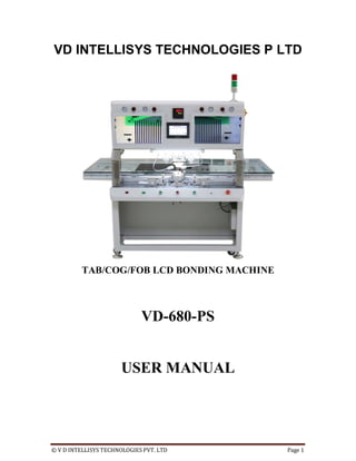
- 1. © V D INTELLISYS TECHNOLOGIES PVT. LTD Page 1 VD INTELLISYS TECHNOLOGIES P LTD TAB/COG/FOB LCD BONDING MACHINE VD-680-PS USER MANUAL
- 2. © V D INTELLISYS TECHNOLOGIES PVT. LTD Page 2 INDEX 1. Company Profile 2. Copyrights & Liability disclaimer 3. Introduction about VD-680-PS 4.packing list 5.Specification 6.lebelling 7.installation 8. Basic Knowledge of Bonding process 9. Machine HMI Introduction. 10. Examples 11. Some Customers photo
- 3. © V D INTELLISYS TECHNOLOGIES PVT. LTD Page 3 COMPANY PROFILE V D INTELLISYS TECHNOLOGY PVT LTD CIN NO: U72900DL2010PTC203285 PAN: AADCV2990E TIN & CST No: 07AADCV2990E2Z8 IEC CODE: 0510058515 The company was founded by two IIT Graduates in 2010. VD INTELLISYS TECHNOLOGIES (P) LTD is the biggest and best manufacturer/distributor of BGA(Ball Grid Array) rework stations & LCD Repair solutions in the world . We provide cutting edge solutions in LCD Panel Repair and SMT LED Production .Our customer includes Foxconn ,Sohnen USA ,DELHI METRO RAIL Corporation, Panasonic, FreeScale Semiconductor, INCable , Vodafone ,IISC Bangalore , SitiCable, Ambuja Cement , IIT Madras , Abacus Peripherals , Attero Recycling, DishTV , Essel Group , HIKVISION,etc. We have also emerged as one of the largest distributor of repairing equipments having dealer network of more than 1000+ across india. Our company has entered this year into e-commerce business selling the educational products, computer/laptop accessories, stationeries though our online portal www.shopsingh.com. VD Intellisys Technologies Sister Company AV CHIPTRONIKS TECHNOLOGY PVT. LTD operates some famous brands in Electronic Industry offering IT sale & Service under the brand CHIPMENTOR and IT repair training under brand CHIPTRONIKS. We have fantastic Customer support team, perhaps the first in the world where the support staff are themselves insanely in love with repair industry. We offer PAN-INDIA Express Shipping on all our products and 99% orders are shipped same day. Our company have total 85 full time employees , out of which 19 are dedicated technical team , 20 in sales , 3 in HR and 6 in marketing and other supporting staffs.
- 4. © V D INTELLISYS TECHNOLOGIES PVT. LTD Page 4 COPYRIGHTS & LIABILITY DISCLAIMER The VD-680-PS package, including any hard copies and soft copies, are copyright protected. The purchase of the programs confers the right to make back-up copies of the software included in the package only. To the maximum extent permitted by applicable law, in no event shall manufacturer be liable for any damages whatsoever (including without limitation, special, incidental, consequential, or indirect damages for personal injury, loss of business profits, business interruption, loss of business information, or any other pecuniary loss) arising out of the use of or inability to use this product, even if manufacturer has been advised of the possibility of such damages. In any case, manufacturer’s entire liability under any provision of this agreement shall be limited to the amount actually paid by you for the SOFTWARE and/or HARDWARE. Safety/Caution instructions For Safety reasons, please note the following carefully This unit operates by electricity & Pneumatic . And some components within the device have high dangerous voltages applied to them. Failing to follow the operating instructions could result in death, serious injuries, and/or extensive damage to property! Never open the housing while main plug is connected. Do not use the units for any purpose other than which they are intended to. Use it according to the operating instructions. This equipment must not be switched on or used without supervision. The unit should switched-off or in idle state while not in use, leaving it ON may cause overheating. Do not place any flammable material on the vicinity of the compressor. Do not allow the spillage of any liquid to on the machine as damage may occur. Please use the machine only on a level and non flammable surface Please do not touch bonding head until it cooled down. Any maintenance of the units is only permitted by a VD INTELLISYS certified service technician. Please also pay attention to the safety regulations applied in your area.
- 5. © V D INTELLISYS TECHNOLOGIES PVT. LTD Page 5 INTRODUCTION VD-680-PS has been designed and manufactured by VD Intellisys Technologies P Ltd after thorough research. This product is suitable for bonding of FPC,COF,TAB and LCD panel and PCB. This machine is used across the world and widely popular among LCD repair technicians and manufacturers of TVs.
- 6. © V D INTELLISYS TECHNOLOGIES PVT. LTD Page 6 Packing List The machine comes in two box : Items in Box 1 : 1. VD-680-PS acf bonding machine 2. Accessories Following are accessories :
- 7. © V D INTELLISYS TECHNOLOGIES PVT. LTD Page 7 Item in box 2 : Platform with glass
- 8. © V D INTELLISYS TECHNOLOGIES PVT. LTD Page 8 SPECIFICATIONS Automatic ACF bonding Machine Equipment Model No VD-680-PS Manufacturer Company VD Intellisys Technologies Pvt Ltd Device Descripion Repair Screen Machine/Bonding Machine Equipment Features 1. Different opearting modes 2. 3 level circuit control 3. Robust design 4. Vacuum Adsorption inbuilt 5. Heavy Weight so no alignment problem Device uses This product is used in a variety of FPC, COF,TAB and LCD Panel and PCB bonding. It can solve LCD vertical,horizontal,vertical band,horizontal beltmblack belt,and many such problems Applicable LCD panel Specifications 15 ‘’-85’’ Applicable LCD panel Thickness 0.3mm-1.1 mm [Single Glass] Binding direction X or Y unidirectional Bonding Head Bit size Replaceableblade according to IC specifications.The original machine is equipped with 45x1.5x10 Device Processing Time TFT: 3.8s/chip Production capacity TAB ,100pc /HR Bonding Accuracy Within ± 1.5μm (Support 4K screen) Highest positioning accuracy setting ±0.5μ m (Currently domestic the highest index) Equipment requirements the work Clean, No dust, Clean room
- 9. © V D INTELLISYS TECHNOLOGIES PVT. LTD Page 9 environment Supply Pressure 0.5~0.7Mpa (Dry air source) Power Supply AC 220V±10%,50HZ,3500W Cylinder Device Japan SMC original thin cylinder Pressure Systems SUNSOM Pressure system parallel bars structure can eliminates Indenter own weight, the pressure minimum accuracy to 0.1KG, pressure part both are use SMC precision components Heating Type Pulse (rapid heating / cooling and auxiliary cooling function) PID Temperature Control Adjustable heating curve Precision PID self- System tuning type of Delta The peak temperature : within +/- 3 degrees Celsius Room temperature time to 180 degrees the response time within 2-3 seconds Materials: Japan Titanium Hot pressing head origin: United States Plane precision (hot press side) :0.001mm Plane thickness 0.5 (Reserved 3 times grinding) Thermocouple Type K type Original US OMEGA wire Industrial control units / Programmer DELTA PLC Touch unit DELTA touch screen Image unit COF counterpoint: down counterpoint Number of lenses : 2
- 10. © V D INTELLISYS TECHNOLOGIES PVT. LTD Page 10 Microscopy: 30-120 Continuous zoom COF Display: 19-inch HD Upper light source : have Down light source : have COF trimming unit Origin: Taiwan Rail Type: U-rail (2056 high) Accuracy : 0.01 Adjustable direction :X/Y/R R Itinerary : Coarse 360 degrees, fine tuning +/- 5 degrees COF Fixture COF mechanical clamping type, Z tilt radius micrometer trimming Lens spinner unit Control mode: X / Y / Z micrometer control Focus Adjustment: Manually adjust the focus Silicone / Teflon Manual switching position LCD stage (platform) Manual sliding or fixed optional Alarm device Pressure abnormal/ temperature anomalies / thermocouple abnormal / action abnormal Hot press head counterpoint Cylinder stop can be set at any position in the vertical direction Control mode Touch screen + button operation Parameter setting According to the need to set up Store multiple sets of hot pressing parameters Rated voltage 180-220 (customizable 110V) Peak power 400-1100W(Supports 68X1.5X10 lengthened tool bit) Maximum power 1100W Actual power 580W Body size 1800X1200x1520mm(L*W*H)
- 11. © V D INTELLISYS TECHNOLOGIES PVT. LTD Page 11 LABELLING
- 12. (C) VD INTELLISYS TECHNOLOGIES PVT LTD , 011-43464998., info@vdintellisys.com INSTALLATION Step-1 open the box 1 gently and take out all the equipments. Remove the air compressor from the top of the machine. Remove the other accessories from storage area on the left side of the machine. step-2 fix the indicator light
- 13. (C) VD INTELLISYS TECHNOLOGIES PVT LTD , 011-43464998., info@vdintellisys.com Step-3 Fix the switch panel
- 14. (C) VD INTELLISYS TECHNOLOGIES PVT LTD , 011-43464998., info@vdintellisys.com step-4 fix the moving glass table frame and put the glass sheet on it. step-5 Fix the pcb platform
- 15. (C) VD INTELLISYS TECHNOLOGIES PVT LTD , 011-43464998., info@vdintellisys.com step-6 Move the machine to desired location and transfer the machine from wheel to fix stand Step-7 install compressor
- 16. (C) VD INTELLISYS TECHNOLOGIES PVT LTD , 011-43464998., info@vdintellisys.com Bonding Technology of FPD(Flat Panel Display) LCD (Liquid Crystal Display) which is the representation of FPD could not do solder junction that is generally used in the world, because it has used ITO (Indium Tin Oxide) electrode formed on the glass substrate since it was the early simple matrix (passive matrix). So, a zebra, heat sealing, etc. are used for circuits’ design of LCD of a segment display, such as a calculator and a clock. Now, LCD of a dot-matrix display widely used for a PC or LCD television have been used ACF (Anisotropic Conductive Film) junction because there are many terminals, the terminal pitch is fine and high precision junction is required. ACF whose connection resistance is low and which excels in heat resistance and connection reliability is used for other FPDs(Flat Panel Display), such as PDP(Plasma Display Panel) and OLED(Organic LED). Zebra rubber: It is the thing that laminates the conductive rubber which added carbon and others as an electric conduction object and insulated rubber mutually. Heat sealing: It is the thing that carries out printing formation of the circuit with thermoplastic conductive adhesives at a film base material. What’s ACF(Anisotropic Conductive Film)? ACF is the matter that applied the adhesives of 10 to 50 micrometer thickness which disperses the electric conduction particle uniformly on the support film (separator) of PET (Polyethylene Terephthalate) etc., and is wound around the reel by the shape of a tape with a width of 1 to 3mm and a length 50 to 200 meter. The true ball-like resin with Ni-Au gild is used for the connection with a glass substrate, and with Ni particles is used for PWB (Printed Wiring Board). By arranging between the circuits which counter and applying heat and force, it is the connection material which can perform electric junction and mechanical adhesion for many electrodes below a 100-micrometer pitch.
- 17. (C) VD INTELLISYS TECHNOLOGIES PVT LTD , 011-43464998., info@vdintellisys.com
- 18. (C) VD INTELLISYS TECHNOLOGIES PVT LTD , 011-43464998., info@vdintellisys.com Bonding mechanism If around 180 to 210 degree heat is applied to a bonding head, the adhesion of ACF falls rapidly. As the mobilized resin flows out of the crevice between up-and-down electrodes, it satisfies the up-and-down electrode circumference, and it is hardens rapidly. Moreover, electric conduction particles are confined between up-and-down electrodes by the pressure applied simultaneously. This metal skin film of the electric conduction particle surface enables the electrical connection between up and down electrodes (anisotropy conductive connection), and make it possible to connect. Fine control of heat and pressure is important for this process, and it is greatly influenced by the rigid conditions of the equipment supporting the kind of ACF to be used, a panel electrode, and a bonding tool etc. The example of a profile of pressure and a temperature setup in an ACF method
- 19. (C) VD INTELLISYS TECHNOLOGIES PVT LTD , 011-43464998., info@vdintellisys.com The connection process of ACF
- 20. (C) VD INTELLISYS TECHNOLOGIES PVT LTD , 011-43464998., info@vdintellisys.com TAB (Tape Automated Bonding) and COF (Chip On Film) There are TAB, COF, etc. in the driver circuit joined to the terminal on the glass substrate of LCD by ACF. TAB has been widely used as a package of a LCD driver. However, conversion to COF is progressing quickly by progress of enlargement of the display of a cellular phone, and colorization. Compared with TAB, COF bonding enables detailed correspondence of a bonding pitch and free arrangement of it. VD Intellisys Technologies Pvt. Ltd offers reliable bonding machine that can solve the characteristic problems of COF such as badness of the mark recognition caused by the thinness of COF.
- 21. (C) VD INTELLISYS TECHNOLOGIES PVT LTD , 011-43464998., info@vdintellisys.com Bonding process : 1. ACF Pre attaching 2. Prebonding 3. Final bonding 1. ACF pre attaching : ACF cut at a designated length is laminated onto the electrode of LCD or TAB/COF, and then the separator film is peeled off. Before peeling off , it is pressed by T bit solder iron 2. Prebonding & Final bonding : We have to bond COF on glass side and PCB side . So you can see in the HMI , there are two parameters: GLASS & another is PCB . The most importance is Glass side. We divide glass side bonding into two stages: (a) Prebonding or manual stage (b) Final Bonding or automatc But before we do bonding we have to do following two things : But before you do this , apply IPA on crystal and head so that no dust remains . (a) Head alignment : For doing head alignment , you have to press the "manual alignment " button on panel . When you press the head will come down , and ou can move head up and down with your hand . So align the head so the head come completely on the glass track .When you press manual alignment again head will go up. you can use this steps repeatedly once you are sure its aligned well. This is just done once to ensure it is aligned well. When you have enough practiceyou dont need this in repetition.
- 22. (C) VD INTELLISYS TECHNOLOGIES PVT LTD , 011-43464998., info@vdintellisys.com (b) Cof alignment : We have to align the cof tracks with the Panel(Glass) tracks .Insert the cof in the Cof plucker.( before that you have to apply acf tape on the cof, 1.2 mtr tape on glass side, 2.0 mtr tape on pcb side) . There are 3 knobs .one is for left and right alignment . second is for top and bottom . Third is for balancing . Every glass have some kind of marks. Some may have + , - or O this knd of symbols. So we have to match these two symbols on both side of screen. (c) After cof alignment , now we have to do prebonding (manualbonding) : So press manual bonding/prebonding on the HMI , head will come down .you can see you can not move up and down with your hand . But if you think head is not aligned , and you want to move head, press cutter head parameter,then you can move head up and down. After you head comes down ,you can apply little heat to head (Press cutter head heating , 1-2 times) . after doing this you can apply little manual cooling , and you can check if your cof is aligned and .you can move it little bit with knobs to align in this stage . After you are sure now enter final bonding (d) Final bonding : For final bonding , click automatic and press two (start buttons together on machine panel) : head will come down automatically, it will follow its profile automatically, will bond and cool automatically and move up automatically. Now you bonding is complete. Follow the above procedure for PCB side : but its lot easier to pcb side , since one side is already connected, so you dont have to do alignment , Just align once and press automatic . VIDEOS : . 1. COF Cleaning : https://www.youtube.com/watch?v=dfWReDxhMb0&t=5s 2. Bonding machine operation manual : https://www.youtube.com/watch?v=cigJIZ6CMXI&t=3s 3. Complete Bonding process : https://www.youtube.com/watch?v=oGvXy_-kuwY
- 23. (C) VD INTELLISYS TECHNOLOGIES PVT LTD , 011-43464998., info@vdintellisys.com MACHINE HMI PREOGRAM DESCRIPTION
- 24. (C) VD INTELLISYS TECHNOLOGIES PVT LTD , 011-43464998., info@vdintellisys.com
- 25. (C) VD INTELLISYS TECHNOLOGIES PVT LTD , 011-43464998., info@vdintellisys.com Description about pressure meter About Pressure meters : There are 4 pressure meters . Two on the right side and Two on the left side . The two pressure meters on the right side determine the value of force that will be applie d by the head in bonding stage on cof. Normally values of Upper Knife will be close to 60 , and value of total pressure little more than 60 . The two pressure meters on the left side determine the movement of head up and down. We have used a special mechanism to move head up an down. it is based on pressure difference . So the value of upper knife will be set to : 60 and lower knife set to Zero (0) . These values need to be just set one time during machine installation.
- 26. (C) VD INTELLISYS TECHNOLOGIES PVT LTD , 011-43464998., info@vdintellisys.com
- 27. (C) VD INTELLISYS TECHNOLOGIES PVT LTD , 011-43464998., info@vdintellisys.com Some of Our customers
- 28. (C) VD INTELLISYS TECHNOLOGIES PVT LTD , 011-43464998., info@vdintellisys.com
- 29. (C) VD INTELLISYS TECHNOLOGIES PVT LTD , 011-43464998., info@vdintellisys.com
- 30. (C) VD INTELLISYS TECHNOLOGIES PVT LTD , 011-43464998., info@vdintellisys.com
- 31. (C) VD INTELLISYS TECHNOLOGIES PVT LTD , 011-43464998., info@vdintellisys.com
- 32. (C) VD INTELLISYS TECHNOLOGIES PVT LTD , 011-43464998., info@vdintellisys.com