Download to read offline


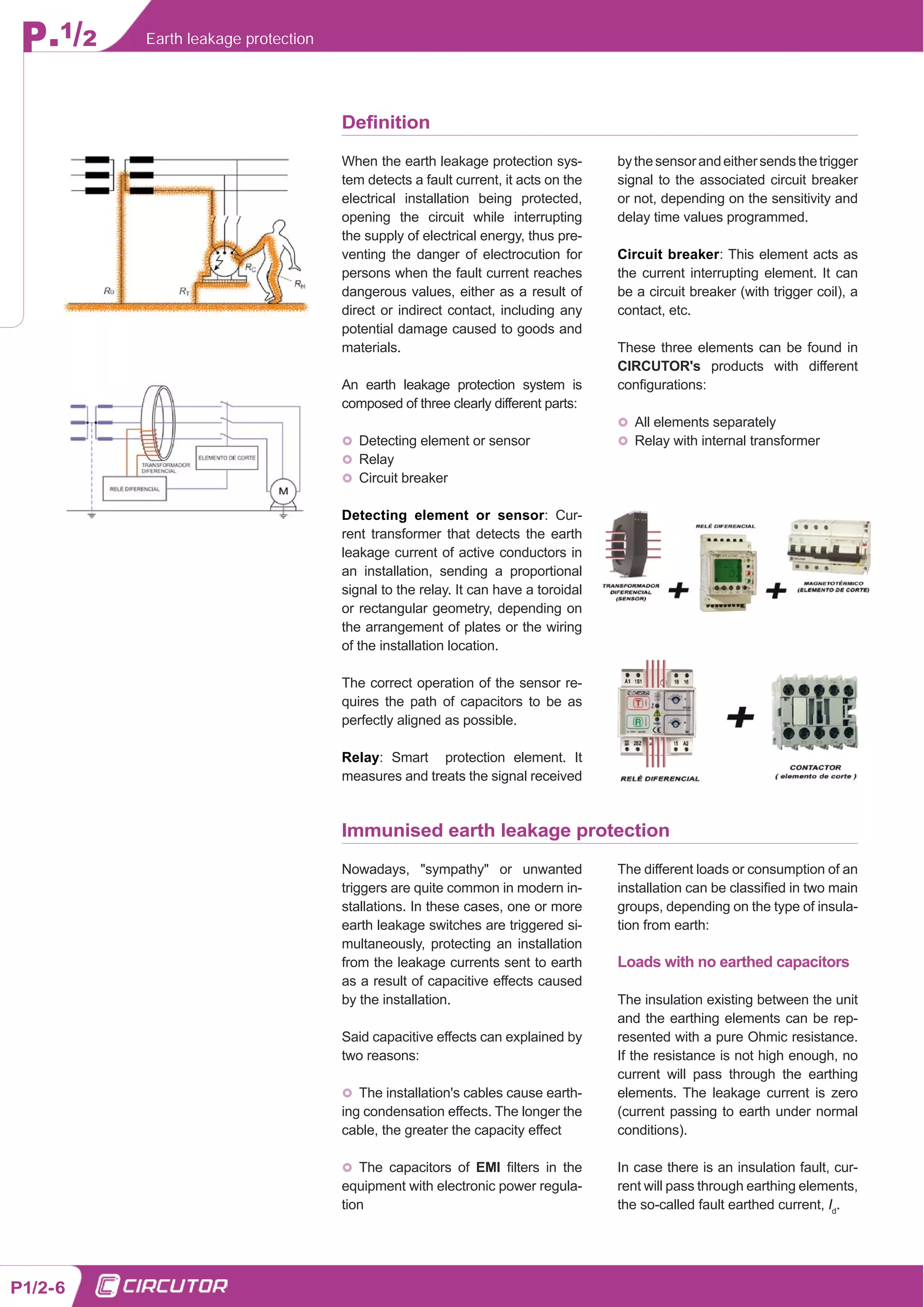


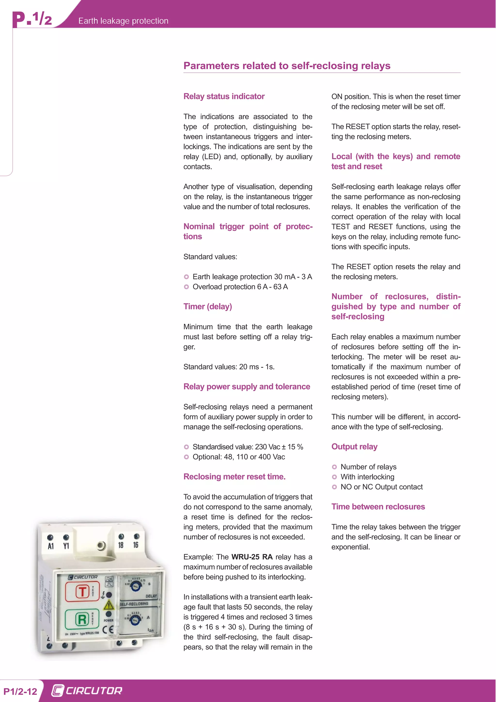
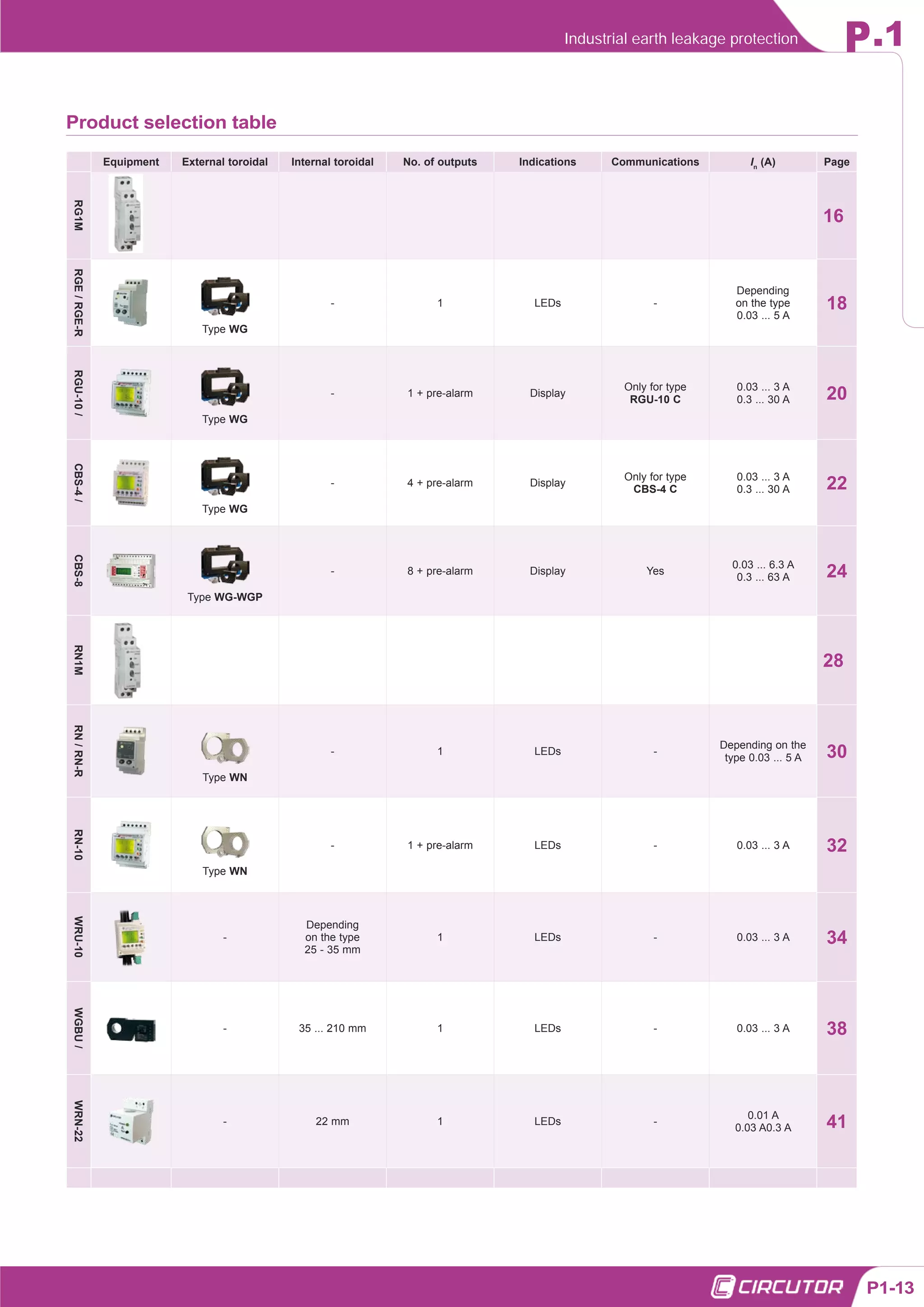


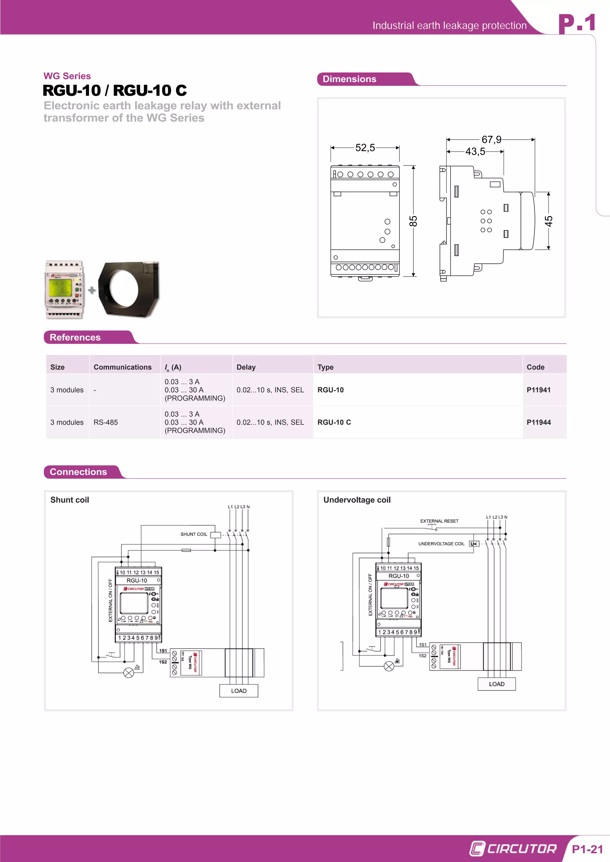

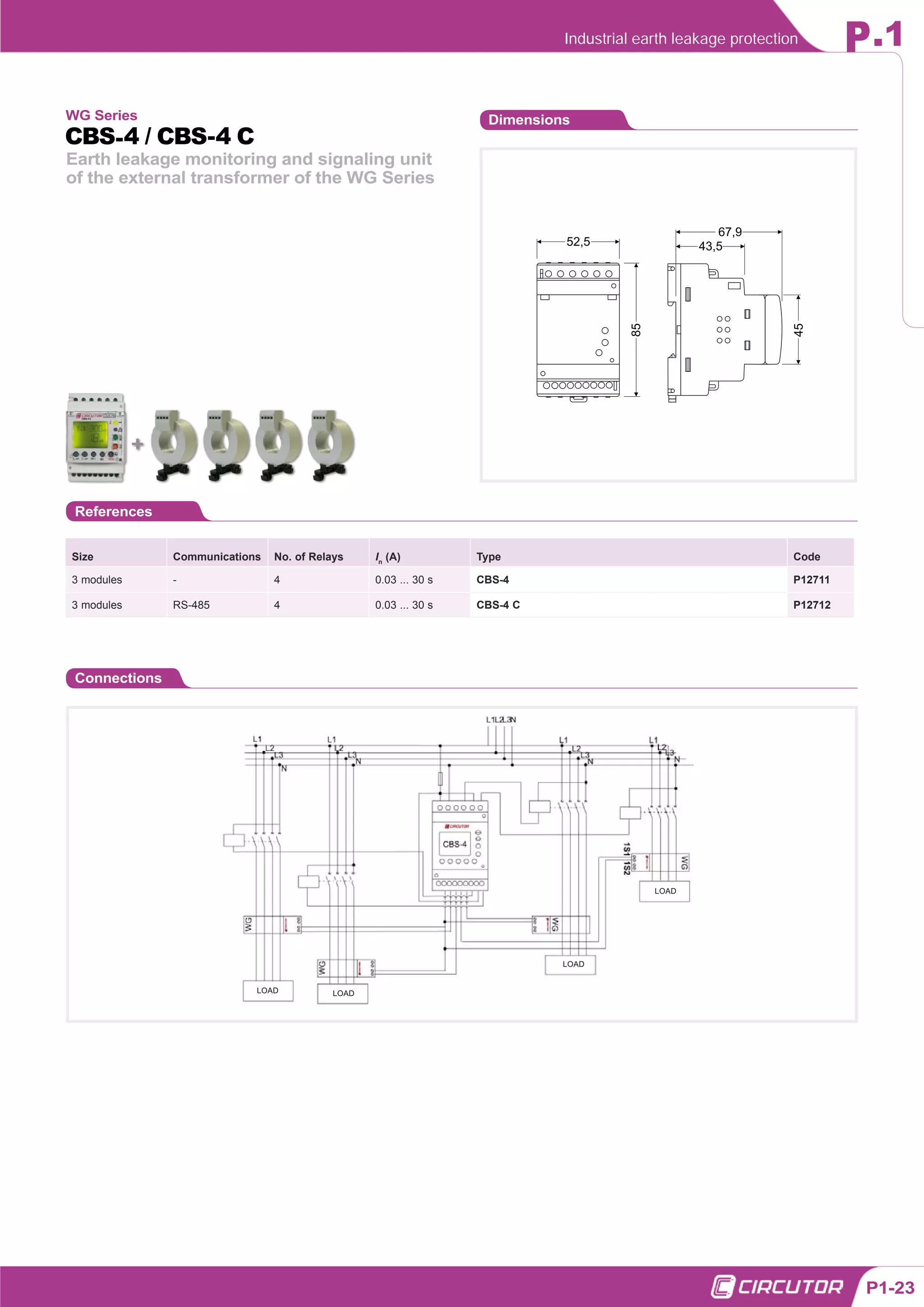


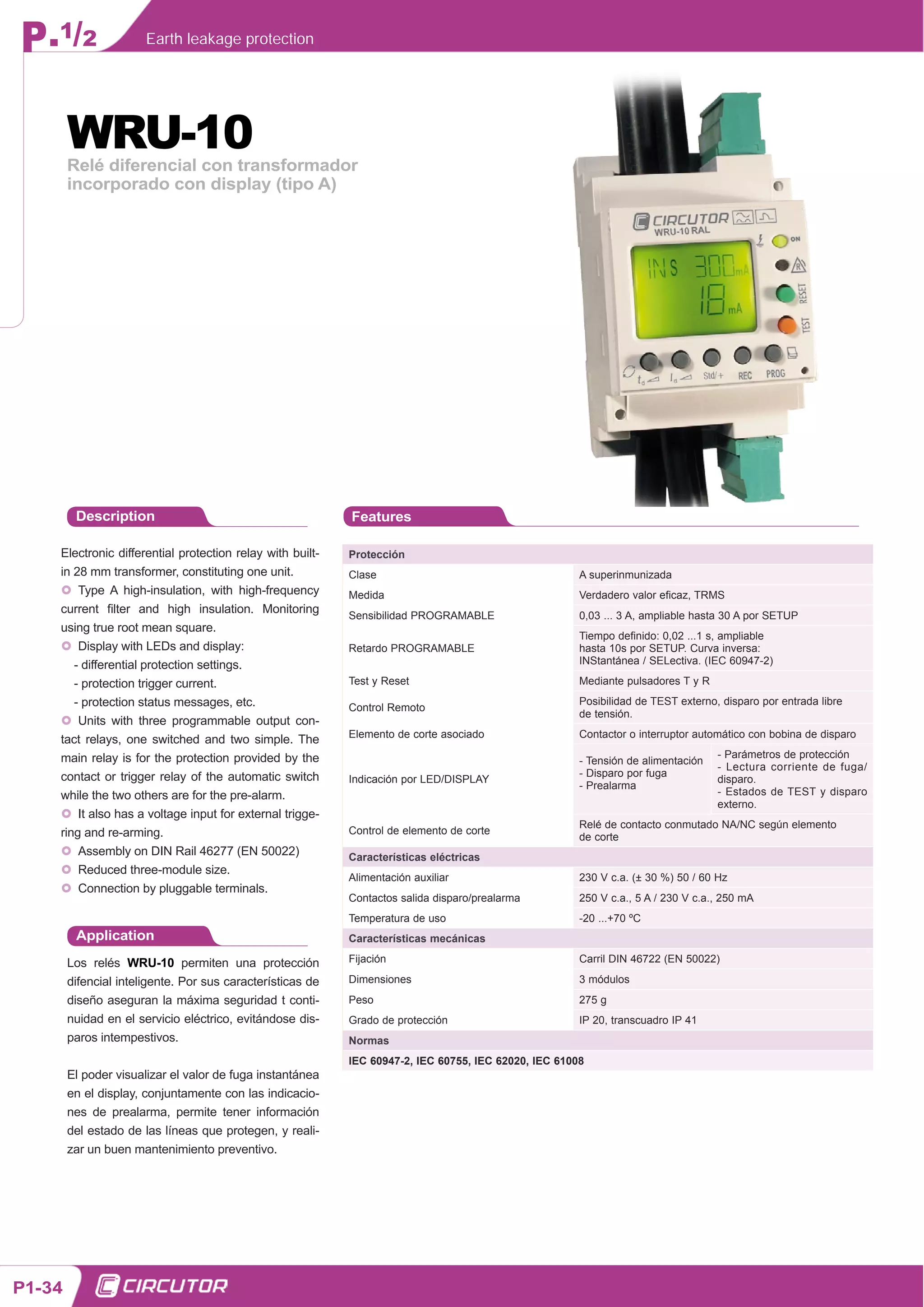


The document details smart earth leakage protection systems, emphasizing their role in maintaining safety and continuity of electrical supply by distinguishing between actual faults and electrical alterations. It discusses various components, including current transformers, relays, and circuit breakers, and highlights the advancements in technology for accurate measurements and reduced false trips. Additionally, the document covers product classifications, operational standards, and the importance of immunity against transient leakages for effective functionality.


