Optic fibres ppt
•Download as PPTX, PDF•
0 likes•436 views

fundamentals of fibre optics for I year engineering students

Recommended
More Related Content
What's hot
What's hot (20)
Similar to Optic fibres ppt
Similar to Optic fibres ppt (20)
Recently uploaded
Recently uploaded (20)
Optic fibres ppt
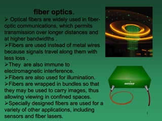
- 1. 1 fiber optics. Optical fibers are widely used in fiber- optic communications, which permits transmission over longer distances and at higher bandwidths . Fibers are used instead of metal wires because signals travel along them with less loss . They are also immune to electromagnetic interference. Fibers are also used for illumination. Fibers are wrapped in bundles so that they may be used to carry images, thus allowing viewing in confined spaces. Specially designed fibers are used for a variety of other applications, including sensors and fiber lasers.
- 2. 2 OPTICAL FIBER • An optical fiber is a glass or plastic fiber that carries light along its length. • Light is kept in the "core" of the optical fiber by total internal reflection. One type of Optic fibre
- 3. WHAT ARE OPTICAL FIBERS ? Optical Fibers are thins long strands of ultra pure glass (silica) or plastic that can transmit light from one end to another without much attenuation or loss. Optical fibers are widely used in fiber-optic communications, which permits transmission over longer distances higher bandwidths (data rates) Fibers are used instead of metal wires because signals travel along them with less loss and are also immune to electromagnetic interference. Fibers are also used for illumination, and are wrapped in bundles so that they may be used to carry images, thus allowing viewing in confined spaces. Specially designed fibers are used for a variety of other applications, 3
- 4. 4
- 5. 5 Fiber Optic Layers • consists of three concentric sections • The core, and the lower-refractive- index cladding, are typically made of high-quality silica glass, though they can both be made of plastic as well. • Core – higher refractive index • Cladding – lower refractive index • Buffer coating – mechanical protection
- 6. 6 OPTICAL FIBER CONSTRUCTION Core – thin glass center of the fiber where light travels. Cladding – outer optical material surrounding the core Buffer Coating – plastic coating that protects the fiber.
- 8. As man’s need for communication increased, the amount of bandwidth required increased exponentially. It was not until Optical Fibers came on the scene that large amount of communication bandwidth became economically and easily available to everyone. As an example, 50,000 voice / data circuit copper cable is massive in size and very expensive, while a single Optical Fiber, the diameter of human hair, can carry 5,00,000 circuits of voice and data. This capacity is increasing day by day as supporting electronics is developing. In itself the capacity of Optical Fibers is limitless. Why Optical Fibers ? 8
- 9. 9 Advantages of fiber optics Much Higher Bandwidth (Gbps) - Thousands of channels can be multiplexed together over one strand of fiber Immunity to Noise - Immune to electromagnetic interference (EMI). Safety - Doesn’t transmit electrical signals, making it safe in environments like a gas pipeline. High Security - Impossible to “tap into.” Less Loss - Repeaters can be spaced 75 miles apart (fibers can be made to have only 0.2 dB/km of attenuation) Reliability - More resilient than copper in extreme environmental conditions. Size - Lighter and more compact than copper. Flexibility - Unlike impure, brittle glass, fiber is physically very flexible.
- 10. 1. VERY HIGH INFORMATION CARRING CAPACITY. 2. LESS ATTENUATION (order of 0.2 db/km) 3. SMALL IN DIAMETER AND SIZE & LIGHT WEIGHT 4. LOW COST AS COMPARED TO COPPER (as glass is made from sand..the raw material used to make OF is free….) 5. GREATER SAFETY AND IMMUNE TO EMI & RFI, MOISTURE & COROSSION 6. FLEXIBLE AND EASY TO INSTALL IN TIGHT CONDUICTS 7. ZERO RESALE VALUE (so theft is less) 8. IS DILECTRIC IN NATURE SO CAN BE LAID IN ELECTICALLY SENSITIVE SURROUNDINGS 9. DIFFICULT TO TAP FIBERS, SO SECURE 10. NO CROSS TALK AND DISTURBANCES ADVANTAGES OF OPTICAL FIBERS 10
- 11. 11
- 12. 1. The terminating equipment is still costly as compared to copper equipment. 2. Of is delicate so has to be handled carefully. 3. Last mile is still not totally fiberised due to costly subscriber premises equipment. 4. Communication is not totally in optical domain, so repeated electric –optical – electrical conversion is needed. 5. Optical amplifiers, splitters, MUX-DEMUX are still in development stages. 6. Tapping is not possible. Specialized equipment is needed to tap a fiber. 7. Optical fiber splicing is a specialized technique and needs expertly trained manpower. 8. The splicing and testing equipments are very expensive as compared to copper equipments. DISADVANTAGES OF OPTICAL FIBERS… 12
- 14. 14 Acceptance angle /cone half-angle • The maximum angle in which external light rays may strike the air/glass interface and still propagate down the fiber.
- 15. 15
- 16. 16
- 17. 17
- 18. 18 MODE OF PROPAGATION • Two main categories of optical fiber used in fiber optic communications are multi-mode optical fiber and single-mode optical fiber.
- 19. 19 SINGLE-MODE FIBERS • single mode fiber • An optical fiber with a core diameter of less than 10 microns. Used for high-speed transmission over long distances, it provides greater bandwidth than multimode, but its smaller core makes it more difficult to couple the light source. Increasingly, single mode fiber is used for shorter distances. When single mode fiber is used in shorter distances, such as a campus or metropolitan area network A typical single-mode optical fiber. Germanium oxide is a dopant of the core silica (Item 1). 1. Core 8 µm 2. Cladding 125 µm 3. Buffer 250 µm 4. Jacket 400 µm
- 20. 20 SINGLE-MODE FIBERS • Single-mode fibers – used to transmit one signal per fiber (used in telephone and cable TV). They have small cores(9 microns in diameter) and transmit infra- red light from laser. • Single-mode fiber’s smaller core (<10 micrometers) necessitates more expensive components and interconnection methods, but allows much longer, higher-performance links.
- 21. 21 MULTI-MODE FIBERS • Multi-mode fibers – used to transmit many signals per fiber (used in computer networks). They have larger cores(62.5 microns in diameter) and transmit infra-red light from LED.
- 22. 22
- 23. 23 Fiber-Optic Cable Single-mode fiber Carries light pulses along single path Multimode fiber Many pulses of light generated by LED travel at different angles
- 24. 24 Fiber Optic Types- based of refractive index • multimode step-index fiber – the reflective walls of the fiber move the light pulses to the receiver • multimode graded-index fiber – acts to refract the light toward the center of the fiber by variations in the density • single mode fiber – the light is guided down the center of an extremely narrow core
- 25. 25 STEP-INDEX Step-index fibers have a uniform core with one index of refraction, and a uniform cladding with a smaller index of refraction. (Air serves as the cladding in the simple glass tube example.) When plotted on a graph as a function of distance from the center of the fiber, the index of refraction resembles a step- function. The figure to the left illustrates how the index of refraction varies with location in a cross-section of a step-index fiber.
- 26. 26 GRADED-INDEX • In graded-index fiber, the index of refraction in the core decreases continuously between the axis and the cladding. This causes light rays to bend smoothly as they approach the cladding, rather than reflecting abruptly from the core-cladding boundary.
- 27. 27 INDEX PROFILE The boundary between the core and cladding may either be abrupt, in step- index fiber, or gradual, in graded- index fiber
- 28. 28 Fiber Optic Signals fiber optic multimode step-index fiber optic multimode graded-index fiber optic single mode
- 29. 29
- 30. 30 Acceptance angle /cone half-angle • The maximum angle in which external light rays may strike the air/glass interface and still propagate down the fiber.
- 31. 31 Numerical Aperture (NA) • Used to describe the light-gathering or light-collecting ability of an optical fiber. • In optics, the numerical aperture (NA) of an optical system is a dimensionless number that characterizes the range of angles over which the system can accept or emit light
- 32. 32 Numerical Aperture (NA) The numerical aperture in respect to a point P depends on the half- angle θ of the maximum cone of light that can enter or exit the lens.
- 34. 34 Fiber-Optic Cable Single-mode fiber Carries light pulses along single path Multimode fiber Many pulses of light generated by LED travel at different angles
- 35. 35 MULTI-MODE FIBERS Multimode fiber has a larger core (≥ 50 micrometres), allowing less precise, cheaper transmitters and receivers to connect to it as well as cheaper connectors.
- 36. 36 MULTI-MODE FIBERS • However, multi-mode fiber introduces multimode distortion which often limits the bandwidth and length of the link. Furthermore, because of its higher dopant content, multimode fiber is usually more expensive and exhibits higher attenuation.
- 37. The step-index optical fibre consists of a core surrounded by a cladding glass of lower refractivity. A light source coupled to the optical fibre emits a cone of light into the core of the fibre. Only rays such as the blue and the magenta ones which meet the the requirement for total internal reflection will be guided in the fibre along a zig-zag path. However, other rays such as the red one will be refracted in the cladding. 37
- 38. 38
- 39. 39
- 40. 40
- 41. 41
- 42. 42
- 43. 43
- 44. 44
- 45. 45
- 46. 46
- 47. 47 Fiber-optic communication 1. is a method of transmitting information from one place to another by sending light through an optical fiber. 2. The light forms an electromagnetic carrier wave that is modulated to carry information.
- 48. APPLICATIONS OF OPTICAL FIBERS… 1. LONG DISTANCE COMMUNICATION BACKBONES 2. INTER-EXCHANGE JUNCTIONS 3. VIDEO TRANSMISSION 4. BROADBAND SERVICES 5. COMPUTER DATA COMMUNICATION (LAN, WAN etc..) 6. HIGHT EMI AREAS 7. MILITARY APPLICATION 8. NON-COMMUNICATION APPLICATIONS (sensors etc…) 48
- 49. 49 Fiber-optic communication The process of communicating using fiber-optics involves the following basic steps: • Creating the optical signal using a transmitter, • relaying the signal along the fiber, ensuring that the signal does not become too distorted or weak, • and receiving the optical signal and converting it into an electrical signal.
- 50. 50
- 51. 51
- 52. 52
- 53. 53
- 54. 54
- 55. 55
- 56. 56