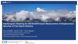
Interferogram Stacking for GB-InSAR-based Measurement of Displacement Velocities of Fast Alpine Glaciers
•Download as PPTX, PDF•
0 likes•370 views

My slides for the 2017 ESA InSAR conference
![Placeholder for organisational unit name / logo
(edit in slide master via “View” > “Slide Master”)
The Bisgletscher
The Bisgletscher, above Randa (VS)
• very fast (up to 2 m/day)
• Several icefalls/avalanches
in the past [1]
• Hazard to life and infrastructure
• Acceleration phase before breakoff
[2]
• Possibility of early warning
Adapted from: M. Funk, Inventar gefährlicher Gletscher der Schweiz
Maps: SwissTopo](data:image/gif;base64,R0lGODlhAQABAIAAAAAAAP///yH5BAEAAAAALAAAAAABAAEAAAIBRAA7)
Recommended
Recommended
More Related Content
What's hot
What's hot (20)
Similar to Interferogram Stacking for GB-InSAR-based Measurement of Displacement Velocities of Fast Alpine Glaciers
Similar to Interferogram Stacking for GB-InSAR-based Measurement of Displacement Velocities of Fast Alpine Glaciers (20)
Recently uploaded
Recently uploaded (20)
Interferogram Stacking for GB-InSAR-based Measurement of Displacement Velocities of Fast Alpine Glaciers
- 1. Placeholder for organisational unit name / logo (edit in slide master via “View” > “Slide Master”) Simone Baffelli1, Othmar Frey1,2, Irena Hajnsek1,3 1Earth Observation and Remote Sensing, ETH Zurich 2 Gamma Remote Sensing AG, Gümligen 3 Microwaves and Radar Institute, German Areospace Center (DLR) Interferogram Stacking for GB-DInSAR-based Measurement of Displacement Velocites of Fast Alpine Glaciers
- 2. Placeholder for organisational unit name / logo (edit in slide master via “View” > “Slide Master”) The Bisgletscher The Bisgletscher, above Randa (VS) • very fast (up to 2 m/day) • Several icefalls/avalanches in the past [1] • Hazard to life and infrastructure • Acceleration phase before breakoff [2] • Possibility of early warning Adapted from: M. Funk, Inventar gefährlicher Gletscher der Schweiz Maps: SwissTopo
- 3. Placeholder for organisational unit name / logo (edit in slide master via “View” > “Slide Master”) Monitoring History Starting 2012, fixed camera: • no operations at night + fog • 2D displacement maps 2014-2015 radar monitoring: • 24/7, with fog + clouds • Differentia interferometry potentially mm precision • only one displacement component • more processing Source: ETH WAV
- 4. Placeholder for organisational unit name / logo (edit in slide master via “View” > “Slide Master”) Radar Hardware: KAPRI • 2015 data acquired with KAPRI • Real aperture imaging • No decorrelation during acquisition • Fully polarimetric • Recently completed calibration Full-pol TCR response Example Pauli RGB (R:H+VV, G:HV, B:HH-VV)
- 5. Placeholder for organisational unit name / logo (edit in slide master via “View” > “Slide Master”) Radar Hardware: Real Aperture Imaging • KAPRI imaging principles: • FMCW ranging • Angular resolution by scanning a narrow beam 2D Imaging • Coherent measurement (intensity + phase) per pixel • Selectable H/V pol in TX and RX • Full polarimetric imaging • Requires calibration
- 6. Placeholder for organisational unit name / logo (edit in slide master via “View” > “Slide Master”) Radar Hardware: Imaging Geometry range azimuth
- 7. Placeholder for organisational unit name / logo (edit in slide master via “View” > “Slide Master”) Displacement phase Ground-Based Differential Interferometry • Fixed installation • Truly zero-baseline • Smaller spatial coverage • Better temporal resolution • Lots of data! • APS different? • Large height difference • Small distance Δ𝜙 = − 4𝜋 𝜆 Δ𝑇𝑣 + 4𝜋 𝐵 𝑛 𝜆𝑅 sin 𝜃 − 4𝜋 𝜆 𝜌 + Δ𝜙 𝑛𝑜𝑖𝑠𝑒 + 2 𝜋𝑛 Topographic phase Disappears for GB- SAR (in fixed installation) Interferometric phase Phase wrapping (undersampled displacement + Atmosphere.) Atmospheric phase (most of this presentation)
- 8. Placeholder for organisational unit name / logo (edit in slide master via “View” > “Slide Master”) D-InSAR Processing Chain Very simple processing: • Combine subsequent pairs • minimize wrapping + decorrelation • Unwrap • Mitigate APS with fit (2x) • Stack (temporal LP filter) • Processing chain automated with Nextflow [4] phase wrapping for 𝑣 = 2 𝑚/𝑑𝑎𝑦
- 9. Placeholder for organisational unit name / logo (edit in slide master via “View” > “Slide Master”) GB Differential Interferometry: APS • Temporal and spatial variations in the refraction index • Well known effect: apparent displacements • Two components: • Turbulent APS • high frequency in time zero mean, uncorrelated temporally • Stratified APS • Lower frequency in time, spatially correlated Interferogram 1 05:20:19 05:22:49 Interferogram 2 05:22:49 05:25:19 Only2minutesapart!
- 10. Placeholder for organisational unit name / logo (edit in slide master via “View” > “Slide Master”) Mitigation of APS: Height Dependent Fit • Remove spatial low-frequency trend by fitting height- dependent model Interferogram (unwrapped) Phase trend Detrended 𝚫𝝓= 𝒂 𝟎 + 𝒂 𝟏 𝒉 DEM in radar geometry
- 11. Placeholder for organisational unit name / logo (edit in slide master via “View” > “Slide Master”) Mitigation of APS: Polynomial fit • Improve estimate with polynomial fit • 𝚫𝝓= 𝒂 𝟎 + 𝒂 𝟏 𝒓 + 𝒂 𝟐 𝒓 𝟐 + … Interferogram (unwrapped, no topo trend) Phase trend Detrended
- 12. Placeholder for organisational unit name / logo (edit in slide master via “View” > “Slide Master”) Stacking • Average N interferograms to mitigate turbulent APS • Assume APS zero-mean in time (and uncorrelated) • Variance of estimate decreases with √𝑁 [3] Interferograms (unwrapped, detrended) Estimated rate 𝑣 = 4𝜋 𝜆 𝑗=0 𝑁 Δ𝜙𝑗Δ𝑡𝑗 𝑗=0 𝑁 Δ𝑡𝑗 Glacier
- 13. Placeholder for organisational unit name / logo (edit in slide master via “View” > “Slide Master”) Results: Stacking, Entire Campaign • N~200 interferograms/day, 1 estimate/day • Low variance • Poor temporal resolution Missing data
- 14. Placeholder for organisational unit name / logo (edit in slide master via “View” > “Slide Master”) Results: Stacking
- 15. Placeholder for organisational unit name / logo (edit in slide master via “View” > “Slide Master”) Stacking: Moving Window • Temporal low-pass filter • Repeat stacking for each window • Result: smoothed timeseries • Assumptions of “regular” stacking
- 16. Placeholder for organisational unit name / logo (edit in slide master via “View” > “Slide Master”) Results: Moving window • High variance of estimation • Worse in afternoon weather? • Not uniform spatially • Better reference point? • APS correlated with topography • Improve removal • Only 1 day of data fully processed so far DEM
- 17. Placeholder for organisational unit name / logo (edit in slide master via “View” > “Slide Master”) Results: Moving Window
- 18. Placeholder for organisational unit name / logo (edit in slide master via “View” > “Slide Master”) Discussion + Outlook • Bisgletscher has been monitored by differential radar interferometry • Estimated velocities agree with current knowledge • Moving window stacking more difficult • Fast atmospheric variation • Strongly depends on day/weather • Future work: • Improve atmospheric modeling • Include spatial correlation etc • Compare several days • Include polarimetric data • Study temporal behavior of APS
- 19. Placeholder for organisational unit name / logo (edit in slide master via “View” > “Slide Master”) Acknowledgments We would like to thank the following persons for their contributions: • Dr. Jan Beutel (PermaSense) for providing infrastructure and logistics • Thomas Wyder for helping with transport and assembly • Jochem Braakhekke for his help during the battery replacement
- 20. Placeholder for organisational unit name / logo (edit in slide master via “View” > “Slide Master”) References [1] Raymond, M., Wegmann, M., & Funk, M. (2003). Inventar gefahrlicher Gletscher in der Schweiz. Mitteilungen Nr 182 der Versuchsanstalt fur Wasserbau, Hydrologie und Glaziologie an der Eidgenossischen Technischen Hochschule Zurich. Retrieved from http://cat.inist.fr/?aModele=afficheN&cpsidt=15381742 [2] Faillettaz, J., Pralong, A., Funk, M., & Deichmann, N. (2008). Evidence of log- periodic oscillations and increasing icequake activity during the breaking-off of large ice masses. Journal of Glaciology, 54(187), 725–737. https://doi.org/10.3189/002214308786570845 [3] Strozzi, T., Wegmüller, U., Tosi, L., Bitelli, G., & Spreckels, V. (2001). Land subsidence monitoring with differential SAR interferometry. Photogrammetric Engineering & Remote Sensing, 67(11), 1261–1270. [4] www.nextflow.io
Editor's Notes
- Observing tiny glaciers with small radar (comparatively) Good afternoon, I’d like to present some experience we had in aqcquiring and processing gb-sar data for the monitoring of fast flowing alpine glaciers. The glacier the title refers to is the Bisgletscher
- Located in the Southwestern Swiss Alps, in the Canton of Valais. The glacier is compartevily tiny, but because of its location and geometry it represents a significant hazard for the neighboring glacier of ranga: in case of a rupture, ice and snow avalanche can reach the neighboring village of randa, causing major disruption. This actually already happened several times in the past. Here monitoring with differential interferometry can help us, because it has been observed that similar unstable glaciers show an acceleration phase before breakoff events, by monitoring the evolution of the velocity, it could be possible to provide early warning.
- Thus the isgletscher has been monitored since 20012 using an automated camera, with all the obvious drawbacks of such as solution, for example the limited availability of data. Thereforem, in 2014 the WAV in collaboration with the FOEN started a monitoring campaign using a portable ground based radar. The campaign was repeated in 2015, where we were involved with our own device…
- Very briefly, the measurements were taken from the other side of the valley, overlooking the glacier, where the Domhutte mointain hut provided us communication and power shared with the Permasense project. The data was mostly processed locally to minimize data transfer through the limited wifi connection.
- The device is KAPRI; a polarimetric extension of GPRI, a portable KU-Band radar interferometer. It operates at a center frequency of 17.2 GHz, with a range bandwidth of 200 MHz, giving a distance resolution of 0.75 m. Being a real aperture system with a limited aperture size, the azimiuth resolution decreases with range. Here on the side you see two example products that we derived from the system during the polarimetric calibration phase.
- And very briefly to help your interpretation of the following results, I’d like to introduce the KAPRI/GPRI imaging geometry, which is quite different to the usual SAR imaging that was shown in most presentation so far. Ranging is achieved with a chirped pulse, as in most SAR system, but 2D images are obtained by azimuthally scanning a narrow beam produced by a large aperture, acquiring images in polar geometry.
- Here on the bottom you see how a typical image looks like when acquired by KAPRI. You can see the usual radar shadowing and foreshortening, but in addition you also notice azimuthal distortion due to the geometry of acquisition. After converting it to polar coordinates, it starts to be more similar to a regular SAR image.
- Another difference of GB-SAR data from regular space/airborne data is in the interferometric processing. Here is the well known expression for the repeat-pass INSAR phase. As always we decompose it in several components, here is the component of interest, proportional to the displacement rate times the temporal baseline. The next component would be proportional to the spatial baseline and the incidence angle and would be the topographic phase contribution. Because the radar is mounted on a fixed installation, there is no topographic contribution in our GB sar acquisition geometry. Additionaly we have the decorrelation contribution and the atmospheric phase scrren, which is the component to which most of the remaining slides will be dedicated to. To briefly summarized, given a series of observations of delta phi at different instants in time, we want to invert one (or more) estimate of the displacement rate v
- Now very briefly, I’d like to introduce the the interferometric processing chain that we used to estimate glacier displacement rates in the 2015 campaign. After acquiring slc data and coregistering them, we perform interferograms between subsequent pairs. Those ensure an high level of coherence and minimize phase wraps (because of the fast flowing nature of the glacier and the short wavelength, one would have motion-induced phase wraps after three minutes already, thus we are already quite close to the maximum if we want to make sue to avoid phase wraps) After computing the interferograms, we unwrap them (also to mitigate phase wrap induced by APS) and then we apply a spatial correction for the APS then we stack several interferograms to further mitigate the APS and arrive at an estimate of V. Because of the large amount of data (200 SLC/day) the analysis has been automated with nextflow, a pipeline management system mostly used in computation biology. Now finally, we can discuss some aspect of the processing chain individually, especially regardin the correction of the APS.
- Very briefly: the so called Atmospheric phase screen is due to changes in the atmospheric refraction index between master and slave acquisitions that cause appearant displacements in the scene. Because those changes usually different spatio temporal statistics compared to the displacement sgifnal of interest, it is possible (at least in theory) to separate those contribution and estimate v. The APS can be mostly again separated into two contributions of very different behaviors: A turbulent contribution, which has high frequency behavior in time and is usually assumed to be zero mean and uncorrelated A stratified component, which is usually more stable in time (in the order of hours) and has a spatial correlation and correlation with topographic features.
- Here is an example of this second trend in an interferogram. For the time being, this trend was modeled as a simple phase slope proportional to the height of each pixel. However, this correction appears not to be sufficient to remove the higher frequency phase trends that we see in the lower part of the image.
- Therefore, we apply a second correction based on a range-dependent polynomial fit to reduce the influence of the stratified atmospheric phase. As you can see, we still can observe high frequrncy (spatial frequrncy) phase trends, especially in the lower part of the image.
- Those trend are probabily partly due to the turbulent APS, which we mitigate by temporal low pass filtering, as the APS has temporal high pass characteristics. To mitigate the turbulent component of the APS, we apply a low-pass filter by averaging several interferograms together, under the estimation of a temporally constant displacement rate and temporally uncorrelated APS. The two components must have different time scales as well. An example fo stacking 15 interferograms (after trying to remove the spatially correlated trend) is shown below. You can clearly see the displacement signal, that was not visible in the individual interferograms because of the superimposed APS.
- Here we applyi the simple stacking approach to the entire 2015 timeseries. These preliminary results were generated dayly directly on the Radars control computed according to the procedure described above and send to the users every day. All the approximate 12 hours of acquisitionswere stacked each day, resulting in very low estimate variance at the cost of very poor temporal resolution, as all the fast glacier dynamics are lost. Because of the lack of reference data, all I can say about the estimates is that they are in line with the prior knowledge of the glacier displacement velocity. The other good news is that the the estimates taken on the reference point outside of the glacier, on the rock do not display any significiant displacement, as it would be expected . You can notice several gaps in the time series, due to times where the radar was not operating because of the lack of power. T
- Here I assembled the daily displacement maps in a small animation that shows the daily displacement estimates (whenever available) for the entire two month period of the 2015 campaign. As you can see, the estimates are visually quite stable for most of the time, but variations in the tounge displacement velocities are very visible. Also interesting is that the fastest part is the icefall region is consistently faster than the rest, as It should be expected.
- The previous method is very simple and works satisfactory when the assumptions are valid, however it can only deliver one displacement rate estimate per interferogram stack, assuming the velocity whiting each stack to be constant. We try to refine it by applying a moving windows: instead of directly average all interferograms together, we only stack a subset at a time and we then move the window so that we always cover the same number of interferograms a different times. Thus, we are applying a moving average filter that corresponds to a temporal low-pass filter. Assuming the previous assumptions to be valid, this should give a better estimate of V at the cost of a loss in temporal resolution.
- Here I processed one day of data (the 8.th of august) by applying the moving stacking method as discussed before. In the plots here we see the estimated LOS velocity (In m/day) for each stacking period. In each stack we combine 15 interferograms and to reduce the amount of data we advance the window by three acquisitions each time. You can see that the estimates tend to be more stable in the morning, as shown by the lower standard deviation and by the very stable velocity estimate at the reference point (which is supposed to have zero displacement rate). However, as the day progresses, something seems to be happeining: the estimates get progressively wilder and the variance increases more and more. I ve prepared a small animaition where I show the interferograms as the day progresses, we can really see that the atmospehere gets progressively chaotic and turbulent as we go towards midday. Theres is probabily a strong correlation between the APS and the local weather conditions, but at this stage I could not analyse it yet.
- Here I assembled the daily displacement maps in a small animation that shows the daily displacement estimates (whenever available) for the entire two month period of the 2015 campaign. As you can see, the estimates are visually quite stable for most of the time, but variations in the tounge displacement velocities are very visible. Also interesting is that the fastest part is the icefall region