Micro-Scholarship, What it is, How can it help me.pdf
Jmad d-15-01294
1. Materials and Design
Manuscript Draft
Manuscript Number: JMAD-D-15-01294
Title: Formation characteristic, microstructure and mechanical performances of Friction Stir Additive
Manufacturing aluminum components
Article Type: Original Article
Keywords: Friction Stir Additive Manufacturing; Aluminum substrate; Formation characteristic;
Microstructure; Mechanical properties, Fracture morphologies
Abstract: In this study, a new solid-state technique of friction stir additive manufacturing (FSAM)
based on FSW principle was used to build successfully a multilayered stack of an Al based component.
The results show that a hook stretches into the nugget zone on advancing side, while it moves upwards
to the periphery on retreating side for a single level welding. With manufacturing the second layer, the
hooks bend outward significantly attributing to the extrusion of above plastic material, and a transition
zone (TZ) is formed near the interface between two layers. In addition, fine equiaxed grains are
observed due to the dynamic recrystallization in the whole. However, a difference in grain size still
exists through the build direction, and in the TZ is forming coarse band grains. A similar change occurs
in the precipitate morphology, size and distribution. Form the top to the bottom, the microhardness
changes dramatically, and a maximum 115 HV at the top is obtained. The tensile strength of all the
slices increases and the elongation decreases slightly in comparison of Al substrate, and the slice top
has the highest mechanical properties, which is attributed to fine grains and desirable precipitate
characterization.
2. 1
To the reviewers:
I have tidied up all pictures of the paper in my way and arranged one by one in my
manuscript.
Also, the pictures are shown in the following:
Fig. 1 Schematic illustration of friction stir additive manufacturing (FSAM) process.
Fig. 2 Dimension of the tensile specimen.
Welding direction
X
Y
Z
Tool rotation
Shoulder
Advancing side
Stirred zone
Retreating side
*Graphical Abstract (for review)
3. 2
Fig. 3 Formation morphologies on the cross section: (a) a single lapped joint, (b) a FSAM component
with nine layers stack and (c) - (f) local magnifications in Fig. (b).
Fig. 4 Schematic diagram of metal flow: (a) hook formation, (b) hook bending and deformation.
(a) (b)
(f)
Bending upwards
(d)
Hook bending
(c) (e)
Hook
(a)
3 mm
(b)
)
5 mm
4. 3
Fig. 5 Macro-figures of the cross sections: (a) a complete FSAM component; (b) a cut part for
microstructural observation.
(a) (b)
5. 4
Fig. 6 Microstructure in different positions: (a) Al substrate; (b) the top in the part; (c) in layer 9; (d) in
interface 9; (e) in layer 7; (f) in layer 5 close the transition zone; (g) in layer 3 adjacent to transition
zone; (h) in layer 2.
(a) (b)
(c)
(e)
(g) (h)
(d)
Transition zone
(f)
Banded structure
6. 5
Fig. 7 BSE images of precipitate distribution in different zones: (a) Al substrate; (b) the top in the cut
part; (c) in layer 9; (d) in interface 9; (e) in layer 7; (f) in layer 5 close the transition zone; (g) in layer 3
adjacent to transition zone; (h) in layer 2; (i) EDS in Fig. 7(h).
Shoulder zone
(b)(a)
Coarse particles in TZ
(f)
(c)
Nugget zone
(e)(d)
Transition zone (TZ)
(g) (h)
20 μm
EDS
(i)
7. 6
Fig. 8 TEM images showing precipitate size, shape and distribution in (a) the upper, (b) the middle, (c)
the lower and dislocation densities of (d) the upper, (e) the lower part of the FSAM component.
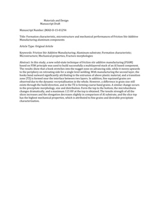
Fig. 9 Microhardness profiles of the cut part: (a) at the horizontal direction; (b) along the build
direction.
-6 -5 -4 -3 -2 -1 0 1 2 3 4 5 6
55
60
65
70
75
80
85
90
95
100
105
Microhardness(Hv)
The width from the FSAM component centreline (mm)
2 mm
5 mm
10 mm
15 mm
25 mm
30 mm
35 mm
(a)
0 3 6 9 12 15 18 21 24 27 30 33 36
55
60
65
70
75
80
85
90
95
100
105
Top
Microhardness(Hv)
Distance from the bottom of FSAM component (mm)
Testing from the centerline
Bottom
(b)
(b) (c)
(d) (e)
(a)
η phase (MgZn2)
10. Research highlight:
A defect free Al based component with 9 layers stack is produced effectively by FSAM.
The formation characteristic including hook, interface and transition zone is studied.
The FSAM part is characterized by fine equiaxed grains and homogeneous precipitates.
The strength of the FSAM slices is higher than Al substrate, especially for the top.
*Highlights (for review)
11. 1
Formation characteristic, microstructure and mechanical performances of Friction Stir Additive
Manufacturing aluminum components
Mao Yuqinga
, Ke Liminga,b*
, Huang Chunpingb
, Liu Fenchengb
, Liu Qianga
a
State Key Laboratory of Solidification Processing, Northwestern Polytechnical University, Xi'an
710072, P.R. China
b
National Defence Key Discipline Laboratory of Light Alloy Processing Science and Technology,
Nanchang Hangkong University, Nanchang 330063, P.R. China
*Corresponding author: Tel: +86 0791 83953312; fax: +86 0791 83953312.
Email address: liming_ke@126.com; maoyuqing1987@mail.nwpu.edu.cn.
Abstract:In this study, a new solid-state technique of friction stir additive manufacturing (FSAM)
based on FSW principle was used to build successfully a multilayered stack of an Al based component.
The results show that a hook stretches into the nugget zone on advancing side, while it moves upwards
to the periphery on retreating side for a single level welding. With manufacturing the second layer, the
hooks bend outward significantly attributing to the extrusion of above plastic material, and a transition
zone (TZ) is formed near the interface between two layers. In addition, fine equiaxed grains are
observed due to the dynamic recrystallization in the whole. However, a difference in grain size still
exists through the build direction, and in the TZ is forming coarse band grains. A similar change occurs
in the precipitate morphology, size and distribution. Form the top to the bottom, the microhardness
changes dramatically, and a maximum 115 HV at the top is obtained. The tensile strength of all the
slices increases and the elongation decreases slightly in comparison of Al substrate, and the slice top
has the highest mechanical properties, which is attributed to fine grains and desirable precipitate
characterization.
*Manuscript
Click here to view linked References
12. 2
Keywords:Friction Stir Additive Manufacturing; Aluminum substrate; Formation characteristic;
Microstructure; Mechanical properties, Fracture morphologies
1. Introduction
7075 aluminum alloy, as a precipitation hardened wrought material based on Al-Mg-Zn-Cu system,
which is considered to be one of the strongest aluminum alloys. Meanwhile, due to the attractive
combination of excellent weldability, high strength to weight ratio, high heat conductivity and good
corrosion resistance, AA7075 is widely used to produce some components in aviation, aerospace fields
and domestic industries [1, 2]. However, a few aluminum alloy parts pertaining to the cabin and
cockpit are normally in irregular and complex configurations, which are difficult to fabricate by the
conventional processing methods such as casting processes. In addition, during the conventional
casting processes, coarser and heterogeneous microstructures and large degrees of segregation are very
easy to generate due to the slow solidification rates [3, 4]. Therefore, such applications of the
traditional casting processes are limited, and some new processing methods are highly desired to cater
to the need for obtaining complex components with fine and uniform microstructures and the stringent
performance requirements laid by the aviation industry.
Additive manufacturing (AM), defined as the process of joining materials to make objects from
three-dimensional (3D) model data, is a new generation of manufacturing processes in which a part is
fabricated by layer-by-layer addition of materials as opposed to traditional subtractive manufacturing
methodologies such as machining or material deformation processes, and is considered to be the most
significant manufacturing approach to have emerged in the last few decades [5-7]. The AM technology
attains considerable recognition and adoption in various industry sectors ever since the first AM
process is introduced in late 1980s [8]. Such a spur in the field of additive manufacturing is realized
13. 3
by the combination of several techniques and comprehensively documented in some review papers [9].
Though, additive manufacturing comes to the forefront by virtue of several innovations that paves its
way, lots of key challenges still persist. For the metal based additive technologies, some special
attentions are laid on the specific characteristics such as build rate, build volume, layer thickness, and
the overlapped structure between layer and layer.
At present, several metal based additive technologies include mainly shaped metal deposition [10],
laser additive manufacturing techniques [11] and electron beam melting [12], and which are heavily
used to fabricate majority of multilayered metal parts. On the one hand, shaped metal deposition can
lead to higher production rates, but it is at the expense of surface finish and dimensional accuracy.
Moreover, when laser additive manufacturing techniques is applied, though a good surface finish is
obtained, the process is still limited due to higher operating costs, low production rate and small build
volumes. On the other hand, some components produced by electron beam deposition perform better
mechanical properties, but it is limited to use owing to the cost factor pertaining to the use of inert
atmosphere. Other issues include that powder particles based substrate used in all the three techniques
are usually contaminated; during the additive process, the substrate is melt into the liquid, and it is easy
to form internal porosity, inclusions and other solidification defects; in addition, the microstructures of
the manufactured component are extremely inhomogeneous and its structural properties are spatially
dependent [13, 14]. Other techniques such as ultrasonic additive manufacturing have the ability to
produce multi-material component, however, the microstructures are highly nonuniform and there exist
great differences between the interface and non-interface, so the structural properties is inferior
compared with the base material [15]. Therefore, a desired requirement for any manufactured
component is necessary to possess a homogeneous microstructure and better mechanical properties.
14. 4
Friction stir additive manufacturing (FSAM), as a new environmentally friendly, energy-effective
solid-state process technology based on friction stir welding (FSW), has a huge potential to fabricate
lightweight materials with high structural performance [16]. During FSAM process, the metal substrate
such as aluminum alloys that are being processed does not melt and recast, which can avoid efficiently
the generation of internal porosities and solidification defects. The fundamentals of FSAM procedure is
easily understood, and it is similar to FSW process while differ in their respective functions. In general,
a non-consumable rotating tool with a special designed pin and shoulder is inserted into slowly the
overlapping surfaces of the plates, and subsequently moved forward along the joint line to be joined.
The schematic of the FSAM process is shown in Fig. 1. Furthermore, the necessary heat to weld the
aluminum substrate is provided by the frictional heat between the rotating shoulder and the workpiece
and the deformation heat achieved by the motion of the pin, and which makes the substrate deform to
result in a circulatory flow of plasticized materials around the pin surface. The plasticized materials
underneath the shoulder are subjected to extruding by the rotation and the traverse movement of the pin
from the advancing side to the retreating side, and the weld nugget is formed while its macro shape is
depended on the geometrical features of the pin. However, current reports about the FSAM are
extremely limited. The friction joining used for the additive manufacturing is under the patent, but it is
only an assumption as a possible route to build 3-D layers [17]. Palanivel et al. [18] reported recently
that the FSAM as a potential technique can attain efficiently Mg based components with high structural
performance through controlling the microstructures. But, some reports on friction stir additive
manufacturing Al based parts are not pursued leading to a lack of literatures on FSAM, and a further
study such as the formation quality, defects and microstructure evolution is also lacked. Therefore, the
aim of this study is to investigate a multilayered build of an Al substrate obtained by FSAM technique,
15. 5
and sequentially stacking layers are performed over the previously processed layer. For the purpose, a
sound tool is designed to join the Al plates, and the formation characterization, microstructure
evolution in the interfaces and non-interfacial zones and mechanical properties of the FSAM Al based
component are further studied.
2. Experimental procedures
In the present study, 5 mm thick plates of 7075 aluminum alloy in annealed condition were used
as base material to additively manufacture. The nominal chemical compositions of AA7075-O are
listed in Table 1, and the tensile strength and elongation of AA7075-O plate are 225 MPa, 17.9%,
respectively. The plates with a size of 200 mm× 40 mm× 5 mm were prepared for longitudinally
friction stir lap welding on a modified horizontal-type milling machine, and the welding direction was
parallel to the rolling direction. A stack of nine layers with a height of about 42 mm were produced by
sequentially building and machining of the lap welded layers. FSAM was carried out using a tool made
of GH4169 steel with a concave shaped shoulder and a left cylindrical threaded pin made. The shoulder
diameter was 30 mm, however, the pin diameter, pin height were 14 mm, 5.2 mm, respectively.
Meanwhile, a constant title angle of the rotating tool of 2° from the vertical axis of FSW machine was
used to contain the material beneath the shoulder, and a plunge depth of 0.2 mm of the pin was kept.
The same welding parameters such as a constant rotation speed of 600 rpm and a fixed traverse speed
of 60 mm/min were used during FSAM.
The specimens for metallographic examination and hardness evaluation were cross-sectioned from
the welded layers perpendicular to the welding direction, and which were ground and polished
following a standard metallographic process. The microstructural features in different positions were
observed by etching in a mixed acid solution of 5 ml nitric acid, 3 ml hydrochloric acid, 2 ml
16. 6
hydrofluoric acid and 190 ml water for duration of 20 s. Microstructural characterization and secondary
phase particles analysis were extensively performed by employing a TESCAN VEGA II-LMH
scanning electron microscope (SEM) equipped with an energy dispersive X-ray spectroscopy (EDX)
system and a JEOL 2010 transmission electron microscope (TEM) operating at 200 keV. For TEM
analysis, the samples of 3 mm circular disks were prepared by twin-jet electro-polish in a solution of 25
vol. % of HNO3 and 75 vol. % of methanol at -30℃, and the voltage of 12V was set up. The hardness
along different build direction from the bottom to top of the cut sample was measured using a HX-1000
model microhardness tester at a load of 0.98 N with a 10 s dwell time, and these measurements were
performed along the centerline in the cut build direction at an interval of 0.5 mm (Z axis). As per the
ASTM: B557M-10, tensile test samples were cut parallel to three directions (X, Y, Z axis) by the
wire-electrode cutting, and subsequently machined to prepare tensile specimens. This was done to
estimate the strength and ductility of different parts of the FSAM component in comparison of Al
substrate. The gage dimension for the tensile sample was 40 mm×10 mm×6 mm, as shown in Fig. 2.
The tensile tests were performed at room temperature using a WDS-100 testing machine at an initial
strain rate of 1 mm/min, and the average value of three specimens was reported. The fracture surfaces
of the tensile samples were analyzed by SEM technique.
3. Results and discussion
3.1 Formation characteristic
Fig. 3 shows the macrostructures of cross sections of different FSAM components and particular
sections of high-resolution images. Among them, a macrograph of the friction stir lap welded joint is
shown in Fig. 3(a). However, the cross-section of the FSAM component involving nine layers stack is
shown in Fig. 3(b), and the local magnified figures of different parts in the component are shown in Fig.
3(c-f), respectively. From the images, it is seen clearly that some obvious defects such as hook, kiss
17. 7
bonding are observed for a single friction stir lap welded joint. Similar results were also reported in Ref
[19]. Since FSAM is considered to be a multiple friction stir lap welding process, the complex feature
of the material flow results in various kinds of defects. For the single friction stir lap weld, one of the
most common defects observed in the interfaces between two welded plates is hook, and it moves
towards to thermo-mechanically affected zone (TMAZ) or weld nugget zone (WNZ). In fact, hook is a
kind of inherent feature and which is characterized as a crack-like unbonded interface that deformed
from the original faying surfaces on the advancing side (AS) and retreating side (RS), as shown in Fig.
3(a). Meanwhile, there is a visible difference in the movement direction of the hook, on the AS the
hook stretches into the WNZ while it moves upwards to the TMAZ on the RS. However, for the
multiple lap joints, it is obviously seen from Fig. 3(b), (c), (f) that, the hook on two sides moves
upwards and does not stretch into the center stirred zone. From the local magnifications, some
overlapped transition zones under each interface and a kiss bonding adjacent to the top periphery are
found in Fig. 3(d) and (e). The main reason is due to result from the complicated material flow during
FSAM.
In the present study, the formation of the hook in a single lapped joint is related to the material
flow in the stir zone affected by the pin with left hand thread and can be interpreted as the following
discussions. On one hand, the stir zone is formed attributing to the cooperation of three material
movement processes: firstly, the stirred material of the lower plates moves upwards and subsequently
incorporate with the material of the upper plate; secondly, the incorporated materials moves
downwards spirally along the left thread pin; finally, the incorporated materials of the upper and lower
plate release from the bottom of the pin, and the above steps are repeated. On the other hand, the faying
surfaces of both plates are vertical to the tool, which makes the oxide layers at the interfaces more
18. 8
difficult to be crumbed sufficiently than those in butt welding. As more materials move upwards from
the lower plates and incorporate with the upper plate material, the stir zone becomes larger and larger.
The original interfaces on both sides are extruded upwards into the stir zone, and which is associated
with changes in material flow direction, from downward to upward, depending on the tool geometry
and welding condition [20]. Consequently, a hook-shaped macrostructure is formed, and the schematic
diagram of the hook formation is shown in Fig. 4(a). During FSAM, when another plate is additively
manufactured, other incorporated materials moves downwards along the pin and extrude the hook
expanding into the stir zone. In turn the hook is bent upwards into the TMAZ due to the upward flow of
the material induced by the tool pin, and the driving force of the upward lower plates is provided by the
shoulder penetration into the surface of the upper plate and the pin penetration into the lower plate
during the dwell period, and the schematic diagram of hook deformation is shown in Fig. 4(b). Similar
results were reported by Badarinarayan et al. [21] and Yin et al. [22]. Furthermore, the formation of the
kiss bonding is owing to the insufficient flow resulted from the incomplete stirring of the pin. While the
generation of the overlapped transition zone beneath the pin is associated with welding thermal cycle
due to a secondary stirring of the pin, and a simple schematic is also shown in Fig. 4(b).
3.2 Microstructure change in different regions
For the FSAM components, the feature of the material flow is very complex due to involving
multiple layers lap joints which are suffering from varying degrees of thermal cycles. As a
consequence, some differences in the microstructures in different non-interfaces and interfaces
between layer and layer still exist. In order to observe the microstructural change in the different
positions, a FSAM component is conventionally cross-sectioned, and then a center stirred zone
with a size of 10mm × 35mm × 2mm is cut off, as shown in Fig. 5 (b). From the picture, it is
19. 9
clearly seen that there is no defects in the center stirred zone. Whereafter, the microstructures of
the cut structure corresponding to the different positions in Fig. 5(b) are observed by optical
microscope, as shown in Fig. 6. For the FSAM process, the original microstructure of Al substrate
plays an important role in the subsequent microstructural evolution, and which is characterized by
coarser banded grains arranged along the rolling direction in Fig. 6 (a). However, experiencing
high peak temperature, strain rate and the welding thermal cycle, FSAM leads to dissolution,
coarsening and dynamic recrystallization, and these processes could occur simultaneously. Seen
from the micrograms, it is found that after FSAM the stirred zone is characterized by a typical
feature with fine equiaxed grains owing to dynamic recrystallization. Moreover, the microstructure
evolution is a very complex process described as follows: (1) at the initial stage the parent grains
split into coarse band structures. As the strain increases, some new elongated fibrous grains are
formed, and then a finer scale is produced when further grain subdivision occur continuously; (2)
with increasing the temperature to the tool, fine nugget scale grains are formed from closely
spaced parallel HAGBs. The bands of fine grains are forced together and increase in volume
fraction with strain; (3) finally, the unstable fibrous grain fragments form a full nugget-like
microstructure consisting of low aspect ratio ultrafine grains. Following welding, the grains
become more equiaxed and are coarsened slightly due to static annealing [23, 24]. Whereas, some
subtle difference in the microstructures between the non-interfaces and interfaces along the build
direction is found from Figs. 6 (b)-(h) corresponding to the locations annotated in Fig. 5(b),
respectively. Obviously, the grain size in different positions is significantly different. From Fig.
6(b), the size in the shoulder zone is somewhat bigger than that of the center zone for a single
welding joint. The main reason is that fine recrystallized grains in the shoulder zone are coarsened
20. 10
due to bigger forging forces, higher peak temperature and longer cooling times. In addition, seen
from Fig. 6(c) and (d) the grain size is also various, and the grains in the ninth non-interface are
smaller than that in the interface. There exists a new transition zone where a banded structure is
formed with lots of coarser grains. Preliminary analysis suggests that the interface undergoes the
second stirring action of the pin when another plate is additively manufacturing, coarse grains in
the original shoulder zone are refined to a degree, while the size in the interface is still larger than
that in the non-interface due to longer time of thermal cycle. The formation of the transition zone
adjacent to the interface is attributed to plastic flow of warmer materials and multiple thermal
cycles during FSAM. Furthermore, it is obvious that the grain size increases from the top to the
bottom through the thickness direction. The explanation is that, when other plates are additively
manufacturing layer by layer, the region at the bottom has to suffer from more thermal cycle and
longer time of static annealing, and which result in more serious coarsening of fine recrystallized
grains.
3.3 Secondary phase distribution
To examine the differences in secondary phase distribution of each local position in the
FSAM component, SEM analysis is done and the micrographs are shown in Fig. 7(b)-(h),
respectively. Compared to that of Al substrate in Fig. 7(a), the particles in different positions are
more uniform and dispersive. As the material after FSAM experiences severe plastic deformation
and high temperature, and the coarse strengthening particles are subjected to broking up,
dissolution and precipitation. In most cases, these processes occur concurrently. Therefore, fine
precipitated particles are dispersively distributed in the stirred zone, as shown in Fig. 7. By EDX
microanalysis, these precipitate phases (white particles) comprise of possible η (MgZn2) and T
21. 11
(AlZnMgCu) phases in Fig. 7(i). Meanwhile, Fig. 7(b)-(h) shows a considerable difference in
particles size in the non-interfaces and interfaces. The precipitated particles in the shoulder zone
are bigger than that in the center stirred zone, as shown in Fig. 7(b), (c), (e) and (h). On one hand,
Fig. 7(c), (e) and (h) refer to the pin dominated flow regimes and are representative of a single
pass welding. Where the metals experience high temperature and great stirring force, and such
high strain rate coupled with high temperature lead to sufficient dissolution of original secondary
phase particles in the Al substrate. Also, the peak temperature above the solvus coupled with a
high cooling rate aids grain boundary diffusion at a lower temperature leading to precipitation at
grain boundaries. However, on the other hand, the shoulder zone dominated plastic flow at the
upper is subjected to more frictional heat supplied by virtue of the shoulder geometry and longer
cooling times, and which can lead fine precipitates to coarsen and grow up abnormally during
subsequent static annealing. In addition, the banded precipitate particles are observed adjacent to
the interfaces from Fig. 7(d), (f) and (g). This may imply that the strain rate and cooling rate
experienced by the interfaces must be lower in comparison to the individual layers.
To analyze further, TEM analysis was done to evaluate precipitate morphology, size and
dislocation densities, and confirm which type these precipitated phases are in different zones, Fig.
11 shows TEM micrographs of different specimens of the FSAM component divided into three
parts marking as the upper, middle, lower, respectively. Seen from the images, some smaller
precipitated phase particles and a higher dislocation density are found at the upper, as shown in
Fig. 8 (a) and (d), respectively. However, at the lower fine precipitates are coarsened seriously and
got to cluster due to undergoing more thermal cycles. By the electron diffraction pattern, we can
distinguish that the elliptic particle is a typical η phase in 7xxx series aluminum alloys, and which
22. 12
is consistent with the results reported in [23, 25]. The supersaturated solid-solution is decomposed
mainly in the following sequence: supersaturated solid-solution → GP zone → η΄ (MgZn2) → η
(MgZn2). Moreover, the fact of a higher dislocation density is in agreement with a large amount of
strain that the material experiences at the upper. Nonetheless, a great decreasing in dislocation
density proves that more recrystallizations occur in the lower part due to more static annealing,
and which is reflected from the microscopic images in Fig. 6.
3.4 Microhardness at different locations
For FSAM component based on aluminum alloy, the microstructure change is characterized
by the hardness variation, and the mechanical performances are also compared. Fig. 9 shows the
microhardness profiles of the component after FSAM, and the curves in Fig. 9(a) represent the
hardness distribution in the horizontal direction of the different thickness, however, Fig. 9(b)
reflects the hardness change along thickness direction in the center zone. The hardness of Al
substrate is in the range of 58-65 HV. It is interesting that there is a significant increasing trend in
the hardness from the bottom to the top of the FSAM component. The maximum hardness of 102
HV is obtained on the top, nevertheless, the minimum value is found in the bottom close to the
base material. The top is obviously harder than the bottom, as shown in Fig 9 (a). Meanwhile, a
similar variation trend in the hardness is presented in Fig 9 (b). However, the hardness in each
overlapped transition zone decreases slightly.
Generally speaking, for the precipitation-strengthened 7075-O aluminum alloy, FSW can not
cause softening in the stirred zone as observing for solid-solution hardened aluminum alloys.
Whereas, experiencing high temperature and severe plastic deformation, fine equiaxed grains are
generated in the stirred regions. As a consequence, the hardness of the stirred zones is all higher
than the Al substrate according to the Hall-Petch relationship (HV = H0 + кHd-1/2
, HV is the
23. 13
hardness, d is the grain size, H0 and кH are the contents) [26]. Moreover, after FSAM the
precipitated particles are smaller and more homogeneous, and which helps to improve the
hardness. But, seen from Fig. 9, the hardness of the whole component presents an asymmetrical
distribution along the thickness direction, and there is an obvious decreasing from the top to the
bottom. This fact is because, with further manufacturing Al plates continuously, the stirred zone in
the bottom undergoes multiple thermal cycles which is similar to a continuous static annealing.
The fine recrystallized grains and precipitated particles in this region are coarsened to different
degrees, and which are seen clearly from Fig. 6 and Fig. 7. Also, a same phenomenon occurs in
those overlapped transition zones adjacent the interfaces. Due to suffering from the second stirring
of the pin, some coarsening of the grains and particles result in a slight decreasing in the hardness
of each transition zone (blue arrows in Fig. 9(b)).
3.5 Mechanical performances
For the FSAM process, the aim is to obtain a complete and defect-free Al based component with
better mechanical performances, so the property changes of different parts are evaluated. Fig. 10 shows
the change curves of different slice specimens and Al substrate. Furthermore, the engineering
stress-strain curves of the tensile specimens are represented in Fig. 10a, and the results including the
strength and elongation of the tensile tests are compared in Fig. 10b, which are the average values
based on three tests. It is clearly shown that the ultimate tensile strength (σb) of different FSAM parts
increases observably compared to base material, but the elongation (δ) decreases slightly. The
maximum σb of the slice locates at the top, which reaches to 278MPa, while the minimum σb of
231MPa presents in the bottom. However, the results of the ductility are opposite, which are 10.4% and
14.8%, respectively.
As the Al substrate experiences intensive plastic deformation and high temperature during the
24. 14
FSAM process, and fine equiaxed grains and uniform precipitated particles are formed in the stirred
zones (in Figs. 6 and 7). In the meantime, during FSAM severe plastic deformation can increase the
internal dislocation concentration, and high temperature enhances the interactions between the
dislocations and other crystalline imperfections, which may increase the resistance force to the
dislocation motion [23, 27]. Therefore, during the tensile test process, fine grains can increase the
distance of dislocation migration and decrease the generation of dislocation pile-ups. And more
uniform and dispersive precipitated particles hinder the dislocation motion, which decreases the stress
concentration and hardly creates the microcracks at the grain boundaries. Even if the microcracks
produce, and a higher resistance to propagation can improve the strength of the FSAM component. The
decreasing of the slices at the bottom is because that the grains and precipitated particles are coarsened
significantly due to continuous static annealing, which is possible to generate lots of the stress
concentration and microcracks [28].
3.6 Fracture morphologies
The fracture surfaces of the tensile test specimens including different slices and Al substrate
are characterized by using SEM, and the fracture morphologies are shown in Fig. 11. It is obvious
that the fracture surface of Al substrate consists of dimples having various sizes and shapes, and
an array of coarser secondary phase particles with elongated shape are peeling off, as shown in Fig.
11(h). Moreover, the dimples in the top slices are deeper and tearing edges are thicker with lots of
micropores, which is an indication that the failure is ductile shown in Fig. 11(a) and (b). However,
compared with the top and middle slices, fewer dimples and fewer tearing ridges are presented in
the fracture surfaces of the bottom slices, and few voids of different sizes and shapes are found in
Fig. 11(f) and (g). These facts indicate that the failures have a brittle fracture pattern of
25. 15
quasi-cleavage with river patterns. The main reason is that the presence of coarser precipitates at
the grain boundaries that are prone to initiate cracks under lower stress during the tensile
deformation. For the ductile tensile specimen, it is possible to sustain the tensile load attributing to
thicker tear ridges, while the brittle sample fails immediately after a commencement of void
coalescence.
4. Conclusions
Friction stir additive manufacturing (FSAM) was used successfully to fabricate a
multilayered stack aluminum alloy component with a higher strength. The formation feature,
microstructure and mechanical performances of the FSAM component were investigated. Based
on the results obtained by experimental results and theoretical analysis, the following conclusions
can be drawn:
(1) For a single pass joint, a hook stretches into the nugget zone on advancing side while it
moves upwards on retreating side. With manufacturing another plate continuously, the hooks bend
outward owing to the second extrusion of plastic material, and an overlapped transition zone is
formed near the interfaces. A complete Al based component of nine layers stack is fabricated.
(2) The dynamic recrystallization leads to fine and equiaxed grains in the stirred zone.
However, a difference in grain size occurs in different positions, and the grains at the top are finer
while the bottom grains are coarsened due to static annealing. Moreover, some coarser banded
grains are produced in overlapped transition zones. The precipitated particles present a similar
trend in morphology, size and distribution.
(3) Compared to Al substrate, the tensile strength of the slices increases significantly while
the elongation decreases slightly. Through the build direction, the strength of the slice increases
26. 16
gradually, and a maximum 279MPa is obtained at the top, which is corresponding to the hardness
profiles.
(4) The fractographs show that plenty of dimples of various sizes, shapes and thicker tearing
ridges present in the top specimen, but the bottom slice present a brittle fracture pattern of
quasi-cleavage with river patterns. The failures of the slice specimens show a mixed brittle-
ductile fracture mechanism.
27. 17
Acknowledgements
This work was supported by the National Natural Science Foundation of China (NSFC) (No.
51265043, 51265042 and 51364037), the Landed Plan of Science and Technology in Colleges and
Universities of Jiangxi Province (No. KJLD12074 and 13055), the open found of the National Defence
Key Discipline Laboratory of Light Alloy Processing Science (No. GF201301003) and the Foundation
of the State Key Laboratory of Solidification Processing in NWPU (No. SKLSP201306).
28. 18
References
[1] Goloborodko A, Ito T, Yun XY, Motohashi Y, Itoh G. Friction stir welding of a commercial 7075-T6
aluminum alloy: grain refinement, thermal stability and tensile properties. Mater Trans 2004;45
(8):2503-8.
[2] Feng AH, Chen DL, Ma ZY. Microstructure and cyclic deformation behavior of a
Friction-Stir-Welded 7075 Al alloy. Metall Mater Trans A 2010;41:957-71.
[3] Brandl E, Heckenberger U, Holzinger V, Buchbinder D. Additive manufactured AlSi10Mg samples
using selective laser melting (SLM): microstructure, high cycle fatigue, and fracture behaviour.
Mater Design 2012;34:159-69.
[4] Vojtech D, Serak J, Ekrt O. Improving the casting properties of high-strength aluminium alloys.
Mater Tehnol 2004;38:99-102.
[5] ASTM F2792-10 Standard Terminology for Additive Manufacturing Technologies, July 2010.
[6] Baufeld B, van der Biest O, Gault R. Additive manufacturing of Ti-6Al-4V components by shaped
metal deposition: microstructure and mechanical properties. Mater Design 2010;31:106-11.
[7] Wohlers Terry. Wohlers report: additive manufacturing and 3D printing state of the industry, Annual
worldwide progress report. Wohlers Associate Inc. 2012:1-287.
[8] Wohlers TT. Wohlers report 2010. Fort Collins, Colorado: Wohlers Associates; 2010.
[9] Buchbinder D, Meiners W, Wissenbach K, Müller-Lohmeier K, Brandl E. Rapid manufacturing of
aluminium parts for serial production via selective laser melting (SLM). Aluminium Alloys. Aachen;
2008:2394-400.
[10] Baufeld B, Van der Biest O, Gault R. Additive manufacturing of Ti-6Al-4V components by shaped
metal deposition: Microstructure and mechanical properties. Mater Design 2010;31:S106-11.
29. 19
[11] Louvis E, Fox P, Sutcliffe CJ. Selective laser melting of aluminium components. J Mater Process
Tech 2011;211(2):275-84.
[12] Lodes MA, Guschlbauer R, Körner C. Process development for the manufacturing of 99.94%
pure copper via selective electron beam melting. Mater Lett 2015;143:298-301.
[13] Sun SH, Koizumi Y, Kurosu S, Li YP, Chiba A. Phase and grain size inhomogeneity and their
influences on creep behavior of Co-Cr-Mo alloy additive manufactured by electron beam melting.
Acta Mater 2015;86:305-18.
[14] Buchbinder D, Schleifenbaum H, Heidrich S, Meiners W, Bültmann J. High power selective laser
melting (HP SLM) of aluminium parts. Phys Procedia 2011;12:271-8.
[15] Dehoff RR, Babu SS. Characterization of interfacial microstructures in 3003 aluminum alloy
blocks fabricated by ultrasonic additive manufacturing. Acta Mater 2010;58(13):4305-15.
[16] Dilip JJS, Babu S, Varadha Rajan S, Rafi KH, Janaki Ram GD, Stucker BE. Use of friction
surfacing for additive manufacturing. Mater Manuf Process 2013;28:1-6.
[17] Dilip JJS, Janaki Ram GD, Stucker BE. Additive manufacturing with friction welding and friction
deposition processes. Int J Rapid Manuf 2012;3:56-69.
[18] Palanivel S, Nelaturu P, Glass B, Mishra RS. Friction stir additive manufacturing for high
structural performance through microstructural control in an Mg based WE43 alloy. Mater Design
2015;65:934-52.
[19] Salari Emad, Jahazi Mohammad, Khodabandeh Alireza, Ghasemi-Nanesa Hadi. Influence of
tool geometry and rotational speed on mechanical properties and defect formation in friction
stir lap welded 5456 aluminum alloy sheets. Mater Design 2014;58:381-9.
[20] Zhang ZH, Yang XQ, Zhang JL, Zhou G, Xu XD, Zou BL. Effect of welding parameters on
30. 20
microstructure and mechanical properties of friction stir spot welded 5052 aluminum alloy. Mater
Design 201;32(8-9):4461-70.
[21] Badarinarayan H, Yang Q, Zhu S. Effect of tool geometry on static strength of friction stir
spot-welded aluminum alloy. Int J Mach Tool Manu 2009;49(2):142-8.
[22] Yin YH, Sun N, North TH, Hu SS. Hook formation and mechanical properties in AZ31 friction stir
spot welds. J Mater Process Technol 2010;210(14):2062-70.
[23] Mao YQ, Ke LM, Liu FC, Liu Q, Huang CP, Xing L. Effect of tool pin eccentricity on
microstructure and mechanical properties in friction stir welded 7075 aluminum alloy thick plate.
Mater Design 2014;62:334-43.
[24] Prangnell PB, Heason CP. Grain structure formation during friction stir welding observed by the
‘stop action technique’. Acta Mater 2005;53:3179-92.
[25] Fu RD, Sun ZQ, Sun RC, Li Y, Liu HJ, Liu L. Improvement of weld temperature distribution and
mechanical properties of 7050 aluminum alloy butt joints by submerged friction stir welding. Mater
Design 2011;32:4825-31.
[26] Sato YS, Urata M, Kokawa H, Ikeda K. Hall-Petch relationship in friction stir welds of equal
channel angular-pressed aluminium alloys. Mater Sci Eng A 2003;354:298-305.
[27] Mahoney MW, Rhodes CG, Flintoff JG, Bingel WH, Spurling RA. Properties of friction stir
welded 7075 T651 aluminum. Metall Mater Trans A 1998;29:1955-64.
[28] Xu Weifeng, Liu Jinhe, Luan Guohong, Dong Chunlin. Temperature evolution, microstructure and
mechanical properties of friction stir welded thick 2219-O aluminum alloy joints. Mater Design
2009;30:1886-93.
32. 22
FIGURE CAPTIONS
Fig. 1 Schematic illustration of friction stir additive manufacturing (FSAM) process.
Fig. 2 Dimension of the tensile specimen.
Fig. 3 Formation morphologies on the cross section: (a) a single lapped joint, (b) a FSAM component
with nine layers stack and (c) - (f) local magnifications in Fig. (b).
Fig. 4 Schematic diagram of metal flow: (a) hook formation, (b) hook bending and deformation.
Fig. 5 Macro-figures of the cross sections: (a) a complete FSAM component; (b) a cut part for
microstructural observation.
Fig. 6 Microstructure in different positions: (a) Al substrate; (b) the top in the part; (c) in layer 9; (d) in
interface 9; (e) in layer 7; (f) in layer 5 close the transition zone; (g) in layer 3 adjacent to
transition zone; (h) in layer 2.
Fig. 7 BSE images of precipitate distribution in different zones: (a) Al substrate; (b) the top in the cut
part; (c) in layer 9; (d) in interface 9; (e) in layer 7; (f) in layer 5 close the transition zone; (g) in
layer 3 adjacent to transition zone; (h) in layer 2; (i) EDS in Fig. 7(h).
Fig. 8 TEM images showing precipitate size, shape and distribution in (a) the upper, (b) the middle, (c)
the lower and dislocation densities of (d) the upper, (e) the lower part of the FSAM component.
Fig. 9 Microhardness profiles of the cut part: (a) at the horizontal direction; (b) along the build
direction.
Fig. 10 Mechanical performances of the FSAM component: (a) stress-strain curves; (b) ultimate tensile
strength and elongation.
Fig. 11 SEM micrographs of the slices: (a) No.1 sample, (b) No.2 sample, (c) No.3 sample, (d) No.4
sample, (e) No.5 sample, (f) No.6 sample, (g) No.7 sample and (h) Al substrate sample.
33. 23
Table 1 Chemical composition (wt. %) of AA7075-O substrate.
Mg Zn Cu Si Fe Mn Cr Ti Al
2.7 5.65 1.7 0.4 0.5 0.3 0.22 0.2 Balance
34. 24
Fig. 1 Schematic illustration of friction stir additive manufacturing (FSAM) process.
Fig. 2 Dimension of the tensile specimen.
Fig. 3 Formation morphologies on the cross section: (a) a single lapped joint, (b) a FSAM component
with nine layers stack and (c) - (f) local magnifications in Fig. (b).
Welding direction
X
Y
Z
Tool rotation
Shoulder
Advancing side
Stirred zone
Retreating side
(f)
Bending upwards
(d)
Hook bending
(c) (e)
Hook
(a)
3 mm
(b)
)
5 mm
35. 25
Fig. 4 Schematic diagram of metal flow: (a) hook formation, (b) hook bending and deformation.
Fig. 5 Macro-figures of the cross sections: (a) a complete FSAM component; (b) a cut part for
microstructural observation.
(a) (b)
(a) (b)
36. 26
Fig. 6 Microstructure in different positions: (a) Al substrate; (b) the top in the part; (c) in layer 9; (d) in
interface 9; (e) in layer 7; (f) in layer 5 close the transition zone; (g) in layer 3 adjacent to transition
zone; (h) in layer 2.
(a) (b)
(c)
(e)
(g) (h)
(d)
Transition zone
(f)
Banded structure
37. 27
Fig. 7 BSE images of precipitate distribution in different zones: (a) Al substrate; (b) the top in the cut
part; (c) in layer 9; (d) in interface 9; (e) in layer 7; (f) in layer 5 close the transition zone; (g) in layer 3
adjacent to transition zone; (h) in layer 2; (i) EDS in Fig. 7(h).
Shoulder zone
(b)(a)
Coarse particles in TZ
(f)
(c)
Nugget zone
(e)(d)
Transition zone (TZ)
(g) (h)
20 μm
EDS
(i)
38. 28
Fig. 8 TEM images showing precipitate size, shape and distribution in (a) the upper, (b) the middle, (c)
the lower and dislocation densities of (d) the upper, (e) the lower part of the FSAM component.
Fig. 9 Microhardness profiles of the cut part: (a) at the horizontal direction; (b) along the build
direction.
-6 -5 -4 -3 -2 -1 0 1 2 3 4 5 6
55
60
65
70
75
80
85
90
95
100
105
Microhardness(Hv)
The width from the FSAM component centreline (mm)
2 mm
5 mm
10 mm
15 mm
25 mm
30 mm
35 mm
(a)
0 3 6 9 12 15 18 21 24 27 30 33 36
55
60
65
70
75
80
85
90
95
100
105
Top
Microhardness(Hv)
Distance from the bottom of FSAM component (mm)
Testing from the centerline
Bottom
(b)
(b) (c)
(d) (e)
(a)
η phase (MgZn2)