2024: Domino Containers - The Next Step. News from the Domino Container commu...
Open ran functional splits
1. Open RAN functional splits, explained
February 24, 2021 By Martin Rowe
FacebookTwitterLinkedIn
Share
Open radio access networks offer the option of placing network functions in different places along the signal
path. That option, called a functional split, lets network engineers optimize performance and make tradeoffs.
Starting with 2G wireless networks, radio access network (RAN) architectures were based on monolithic
building blocks. Those networks — and many 5G networks as well — have contained functions in proprietary
boxes called baseband units (BBUs) at the base of radio towers. BBUs demodulate the RF signal, converting
the output into digital data streams for transport on the backhaul to the core network. That situation is changing
and becoming more open.
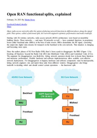
Since the earliest phases of 5G New Radio (NR), there’s been a push to disaggregate the BBU (Figure 1) by
breaking off functions beyond the Radio Unit (RU) into Distributed Units (DUs) and Centralized Units (CUs).
The argument for disaggregation was flexibility, letting network operators decide how to locate these functions
and maximize performance. Flexible hardware and software implementations allow scalable, cost-effective
network deployments. For disaggregation to happen, hardware and software components must be interoperable,
letting network engineers mix and match these units from different vendors. Disaggregation also brings
tradeoffs in deciding which unit should control certain operations — the functional split.
2. Figure 1. The Open RAN concept separates the Distributed Units and Centralized Unit from a proprietary
Baseband Unit, connecting them with open interfaces. Source: Parallel Wireless.
Open RAN is about horizontal openness — with open interfaces enabling functions of the RAN to connect with
other functions, from a radio unit (RU) to a baseband (DU-CU), to the controller to the NMS/orchestrator. With
flexibility comes tradeoffs. Where should network functions reside. While it’s clear that RF functions need to
be in the RU, the rest is a decision.
A split architecture (between central and distributed units) allows for coordination of performance features such
as latency and cost. Network engineers must decide among load management, real-time performance
optimization, and adaptation to various use cases to maintain quality of service (QoS). Gaming, voice, video,
have different latency tolerances. These services depend on different transport and deployment scenarios, like
rural versus urban, that have different access to the fiber that transports data.
The functional split concept was introduced for 5G, though it can be applied to 2G, 3G 4G as well. These
previous generations, with their lower data rates than 5G, can still benefit from Open RAN, though not to the
extent of 5G.
When the RAN is opened up horizontally, it could bring in a new range of low-cost radio players, and it gives
mobile operators a choice to optimize deployment options for specific performance requirements at much better
cost.
RAN Functional Splits
3GPP considered the split concept (DU and CU) for 5G from the beginning of writing its specifications. The
DU is responsible for real time layer 1 (L1, physical layer) and lower layer 2 (L2) which contains the data link
layer and scheduling functions. The CU is responsible for non-real time, higher L2 and L3 (network layer)
functions.
While CUs will maintain BBU-like functionalities such as digital processing, DUs are software based and could
contain some functions related to the Remote Radio Head (RRH) contained in the RU. This is where the Open
RAN concept comes in: from COTS-based servers for DU and CU software to RU from any vendor.
RU: This is the radio hardware unit that coverts radio signals sent to and from the antenna into a digital
signal for transmission over packet networks. It handles the digital front end (DFE) and the lower PHY
layer, as well as the digital beamforming functionality. 5G RU designs are supposed to be “inherently”
intelligent, but the key considerations of RU design are size, weight, and power consumption. Deployed
on site.
DU: The distributed unit software that is deployed on site on a COTS server. DU software is normally
deployed close to the RU on site and it runs the RLC, MAC, and parts of the PHY layer. This logical
node includes a subset of the eNodeB (eNB)/gNodeB (gNB) functions, depending on the functional split
option, and its operation is controlled by the CU.</li
CU: The centralized unit software that runs the Radio Resource Control (RRC) and Packet Data
Convergence Protocol (PDCP) layers. The gNB consists of a CU and one DU connected to the CU via
Fs-C and Fs-U interfaces for CP and UP respectively. A CU with multiple DUs will support multiple
gNBs. The split architecture lets a 5G network utilize different distributions of protocol stacks between
CU and DUs depending on midhaul availability and network design. It is a logical node that includes the
gNB functions like transfer of user data, mobility control, RAN sharing (MORAN), positioning, session
management etc., except for functions that are allocated exclusively to the DU. The CU controls the
operation of several DUs over the midhaul interface. CU software can be co-located with DU software
on the same server on site.
3. Because the RAN functional split architecture (Figure 2) is fully virtualized, CU and DU functions runs as
virtual software functions on standard commercial off-the-shelf (COTS) hardware and be deployed in any RAN
tiered datacenter.
Figure 2. Open RAN disaggregation with RU, DU, CU offers several options for locating RAN functions.
Source: Parallel Wireless
As the functions are virtual, several independent instances of DU and CU can share the same physical (server)
resources. This allows several RAN services to run on the same hardware, each with their own requirements
and resource needs fulfilled.
There are three purposes of separating DU functionality from RU:
To reduce cost. Less intelligent RUs cost less.
Ability to look at a sector of RUs at once and not just an individual RU. This will help to enable features
like CoMP.
As processing is done in the DU, resources can be pooled resulting in pooling gains.
The centralized baseband deployment enables load-balancing among different RUs. In most cases, the DU will
be co-located near one or several RUs and conduct intense processing tasks such as Fast Fourier
Transform/inverse Fast Fourier Transform (FFT/IFFT) used in OFDMA modulation. Edge-centric baseband
processing delivers low latency, local breakout, seamless mobility with real-time interference management, and
optimal resource optimization.
The CU’s server and relevant software can be co-located with the DU or hosted in a regional cloud data center.
The actual split between DU and RU (Fig. 2) may be different depending on the specific use-case and
implementation (the O-RAN Alliance definition is Option-7.2 and Small Cell Forum is Option-6). The option
number increase as you approach the RU and the physical layer. That’s in opposition to the traditional OSI
model where layer 1 is the physical layer.
While the CU/DU split adds flexibility in how RAN services are deployed, RU cost still needs addressing.
Today, the interface between the BBU and RU in 4G LTE is proprietary to mobile equipment vendors and is
based on the Common Public Radio Interface (CPRI) interface. CPRI is not an open interface. It has
dependencies in the implementation of BBUs and RRHs that require both to come from the same vendor.
Furthermore, it creates a bottelneck; it’s based on transport of digital radio signals directly over a point-to-point
4. optical fiber. That creates a cost issue when a point-to-point fiber connection needs to be made between
multiple microcell RUs to BBUs installed 20 km away. The CPRI interface requires a constant bit rate no
matter the load and there is no possibility for statistical multiplexing.
In 2017, Ericsson, Huawei, NEC, and Nokia introduced an update to this interface called enhanced CPRI
(eCPRI). The eCPRI interface uses Ethernet as the L2 interface, which lets existing solutions for control,
management and synchronization to be used. Ethernet allows packet-based switching and statistical
multiplexing of several RU connections onto a single backhaul fiber, reducing the cost of deploying micro-
cells.
The industry is coming to a consensus that the lower level interface that connects RU and DU (fronthaul)
should be eCPRI, which delivers the lowest latency at a lower cost. eCPRI specifies a number of split options in
the protocol stack and, as Figure 3 shows, these options align with 3GPP RAN functional and those from the O-
RAN Alliance.
Figure 3. Propietary CPRI interface (left) versus open eCPRI interface being able to support low latency at
much lower cost.
As fronthaul latency is constrained to 100 µsec, using eCPRI interface helps with it. As Figure 4 shows, a
single DU may serve RUs up to many kilometers away. Using eCPRI becomes cost-effective.
The DU/CU split is hardly impacted by the type of physical infrastructure. The primary new interface is the F1
interface in Figure 4 between the DU and CU. Midhaul connects the CU with the DU. While there can be
different splits, the only one being considered de-facto between DU and CU is Option-2. There’s also very little
difference on the midhaul interface between the different splits (1-5). The latency on the link should be around
1 msec. A centralized CU can control DUs in an 80 km radius.
5. Figure 4. The Open RAN F1 interface between the DU and CU becomes the midhaul link. Source: Altran
(Aricent)
Backhaul connects the 4G/5G core to the CU. The 5G core may be up to 200 km away from the CU.
With the increase in deployment footprint, fiber and availability of required front hauls can be challenging. By
distributing protocol stacks between different components (different splits), network engineers and providers
can focus on addressing the tight requirements for a near-perfect FH between RU, DU and CU.
Which split?
The choice of how to split NR functions in the architecture depends on some factors related to radio network
deployment scenarios, constraints and intended supported use cases. Three key ones are:
A need to support specific QoS per offered services (e.g. low latency, high throughput for urban areas)
and real/non-real time applications.
Support of specific user density and load demand per given geographical area.
Available transport networks with different performance levels, from ideal to non-ideal.
Mobile operators need the flexibility to pick and choose different splits based on the same COTS-based
hardware and network components. The flexibility comes from using different software implementations.
Protocol layers can reside in different components based on fronthaul availability and deployment scenarios.
This approach will reduce the cost of operations and total cost for mobile operators.
Higher functional splits are more desirable for capacity use cases in dense urban areas while lower functional
splits will be the optimum solutions for coverage use cases. So, while lower functional splits utilize less than
perfect fronthauls, there is a greater dependence on fronthaul performance for higher functional splits (Figure
5).
6. Figure 5. Functional splits divide network functions such that the remote radio unit may contain RF only or
more functions such as the PHY layer, MAC layer or RLC layer depending on network requirements. Source:
Parallel Wireless
The mapping of functions to devices results in different functional RAN split options. That is, to which layers
of the protocol stack are mapped to an RU, DU or CU. The split between DU and RU is now formally defined
by 3GPP.
This new split-RAN architecture makes it possible to deploy the DU and CU functions either centrally or at the
edge close to the RU depending on latency and backhaul bandwidth requirements. Thus, it provides greater
flexibility in meeting different deployment scenarios.
To take full advantage of split architecture that can deliver interoperability, ability to select best-of-breed
components, and scalability, any network needs support for2G, 3G, 4G, and 5G baseband functions (Figure 6).
For the best latency support requirement, baseband functions DU and CU software are decoupled from
hardware and are deployed on NFVI or as containers. An MNO can use any VM requirements and/or any
hypervisor or orchestration provider to enable these functional splits.
Different RAN functional splits work for different use cases.
7. Figure 6. DU and CU software can be bare metal or containerized depending on the deployment requirements
deployment.
One split might not fit all. A solution that can support many technologies including not just 4G and 5G, but 2G
and 3G, is the most attractive to mobile network operators (MNOs) as it will simplify network management and
reduce cost. Split 7.2 is the best for 4G and 5G; split 8 will be the best option for 2G and 3G. Both options can
run over 7.2 Open RAN radios.
RAN Functional Split 6: Small cell split
The Small Cell nFAPI (network FAPI) interface in RAN functional split 6 of Figure 7 is enabling the Open
RAN ecosystem by allowing any small cell CU/DU to connect to any small cell radio unit (S-RU). 5G FAPI
encourages competition and innovation among suppliers of small cell platform hardware, platform software,
and application software by providing a common API. These interfaces will help network architects by letting
them mix distributed and central units from different vendors.
8. Figure 7. In Split 6, the RF, upper PHY, and lower PHY layers reside in the radio unit. Source: Small Cell
Forum
RAN Functional Split 7: Dense and urban areas
In case of requirements for more delay-sensitive service, based on appropriate fronthaul availability, the MAC-
PHY split will be the preferred solution. Option 7 Split architecture is where the DU handles the
RRC/PDCP/RLC/MAC and higher PHY functions, whereas the RU handles the lower PHY and RF functions.
CU functionality may be embedded with the DU on the same server, or it can be pushed up the network as a
virtualized aggregation entity, along with an OpenRAN Controller or aggregator. Option 7 (Figure 8) lets
operators share or pool gains while maintaining the lowest processing utilizations on both the DU and RU –
leading to a very cost-effective option with a low cost and an ideal option for a distributed RAN deployment,
including Massive MIMO.
9. Figure 8. Split 7 moves the upper PHY layer to the DU. Source: Parallel Wireless
Higher splits, as in 7.x are ideal for 4G and 5G and can support traffic in dense urban areas.
The O-RAN Alliance has defined a multi-vendor fronthaul interface between DU and RU based on Split 7-2x.
In O-RAN terminology, RU is denoted as O-RU and DU is denoted as O-DU.
The fronthaul specifications include Control, User and Synchronization (CUS) & Management (M) plane
protocols, as indicated in Figure 9.
10. Figure 9: O-RAN Architecture. Source: O-RAN Alliance
RAN Functional Split 8: For 2G and 3G
Additionally, O-RAN Alliance facilitates multi-vendor integration by defining suitable interoperability (IOT)
profiles, test configurations and test cases, so that the 3GPP-related radio conformance testing remains
independent from the O-RAN fronthaul testing.
Split 8 is based on the industry standard CPRI interface and has been around for a while. With traffic split 8, all
functions (from PHY to RRC layers) except for RF are handled by the DU, while the RF layer reside in the
radio (Figure 10).
11. Figure 10. At Split 8, only the RF hardware resides in the radio unit. Source: Parallel Wireless
Split 8 is highly effective in 2G and 3G, where traffic rates are much lower (and therefore processing itself is
lower, to a certain extent) and can be easily done on an x86 server, while allowing operators to use cost-
optimized RUs with minimal logic and processing. The DU and RU should be interoperable with other third
party DUs and RUs. The enhancement over the legacy Split-8, is that for RUs to run multiple technologies over
the same fronthaul interface, they now need to utilize eCPRI instead of the legacy CPRI interface between the
RU and DU. This approach allows for centralized traffic aggregation from the RUs, which in turn enables a
seamless migration path from the traditional LTE ecosystem to the NR ecosystem.
The RAN DU real-time L2 functions and baseband processing. In the O-RAN Alliance working group, the DU
is proposed to support multiple RUs. To properly handle the digital signal processing and accelerate network
traffic, an FPGA can be used. Hardware acceleration is considered a requirement for 5G but less so for 2G, 3G,
and even 4G.
There has also been a focus around hardware accelerators — FPGA and GPU — to accelerate real-time
sensitive processing for the lowest layers of the 5G radio baseband. FPGAs in the RU not only perform digital
processing tasks but can also integrate some of the analog subsystems. Xilinx, for example, has integrated
mixed analog digital subsystems (including DACs and ADCs) into its RFSoC device family.
Ericsson and Nokia are looking at GPU-based acceleration for some virtual RAN (vRAN) workloads,
especially for 5G M-MIMO and for AI. Reducing overall cost will be a priority, and a solution around GP
processor architectures to deliver the most efficient and cost-effective compute, storage and network elements
will drive the innovation.
Real-life Implementations
O-RAN alliance has already specified O-Cloud (O-RAN Cloud) as O-RAN includes the cloudification of RAN
for single or multi tenants and automation of RAN end-to-end. O-Cloud (Figure 11) includes both edge cloud
(vCU) and far edge cloud (vDU/vRU).
12. Figure 11. O-Cloud brings some O-RAN functions to the cloud. Source: O-RAN Alliance
As the edge equipment is required to be compact, energy efficient and ruggedized, many operators and vendors are
leaning towards deploying DU and CU on site (far edge cloud) on one server to reduce deployment cost and complexity.
Based on their experience, Nokia (Figure 12) believes that the only valid split is between RU and DU. Time will tell if
integration of one vendor’s DU with another vendor’s CU will deliver flexibility and savings.
Figure 12. Nokia’s view of Open RAN is to have a functional split between the Ru and DU but keep DU and CU
functions centralized. Source: Nokia
Overall, you can expect RAN Functional splits to lower network costs if interfaces between hardware and software
components are open.