1. Sensorless Control of Active Magnetic Bearings
Supervisor Candidate
Prof. Iustin Radu Bojoi Antonio Caruso
Introduction
The active magnetic bearing, taking advantage of the forces
generated by the electromagnetic field is able to support the
rotor without mechanical contacts providing a friction-free
operation, suitable for high speed rotating machinery.
The aim of this dissertation is the study, simulation and im-
plementation of an active magnetic bearing which avoids the
employment of position sensors and for this reason its control
is referred to as sensorless. The complete model was firstly
designed and simulated in Simulink, then the switching power
amplifier programmed by means of the VHDL code was tested
on the real machine.
I. Self-Sensing Method
The self-sensing technique in addition to a predictable hard-
ware complexity and cost of maintenance reduction, entails an
increase of reliability and compactness of the system. Accord-
ing to the literature, the sensorless technique can be divided
into two categories: the observer based principle in which
the gap length is estimated by means of the phase voltage
and current considering the system as a system state and the
modulated based approach. In this thesis the latter was em-
ployed, in particular the amplitude modulation referred to as
PWM ripple based, that by means of a two level switching
amplifier imposes a ripple on the phase current whose ampli-
tude depends by the phase inductance and consequently on
the position of the rotor. To extract the position information
is used a demodulation technique consisting of a band pass
filter to clean the signal by the components not depending by
the rotor position, a rectifier and a low pass filter.
The PWM ripple based approach is counterposed to the in-
jection of high-frequency signals method, mainly avoided due
to the needing of additional hardware.
II. Active Magnetic Bearing System
The AMB under analysis provided by the company Chideu
GmbH, is a heteropolar bearing whose characteristics are
Parameter Symbol Value Unit
Shaft inner diameter dm 8 mm
Shaft outer diameter dr 20 mm
Rotor shaft lenght lw 600 mm
Rotor mass m 0, 9 kg
Air gap sl 1, 1 mm
Pole width − 5 mm
Electrical sheet thickness − 40 mm
Turns(per pole) N 144 -
Cable cross section − 1 mm2
Coil inductance L 5 mH
Coil resistance R 0, 7 Ω
Table 1: Magnetic Bearings’ charecteristics.
listed in the table 1. It has to replace a ceramic bearing
in use for a Synchronous Reluctance Machine.
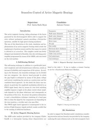
Figure 1: Bearing with Bearing Cap
III. Simulations
In order to support the Simulink model, simulations consider-
ing saturation and non linearity was provided by the company,
analyzing the main relations such as the electromagnetic force
1
2. in respect to the current or the inductance in respect to the
displacement, by means of the finite element analysis. The
model implemented in Simulink can be divided into three
main blocks: sensorless estimator, bearing coil model, force
model. It is worth mentioning the PID controller whose pa-
rameters were tuned with the Ziegler-Nichols method that
although time-spending and guarantees neither stability nor
high performance of the results, is largely used for non-linear
systems. The estimator model is based on the paper ”Self-
Sensing Active Magnetic Bearing Using 2-Level PWM current
Ripple Demodulation” [Gruber W., Pichler M., Rothboch M.,
Amrhein W.] and it results to be:
2*pi*Bs
s +2*pi*Bs+(2*pi*fs)^22
Band Pass Filter
w
s+w
LowPass Filter
pi^3*fs*a/8
|u|
Abs
1/U
0.0011
Is 1
Out
Figure 2: Demodulation Process
With is the phase current:
is = i0 +
4ˆs
π2µ0AN2fP W M
UDC sin(2πfP W M t) (1)
i0 represents the bias current that linearizes the non linear
force characteristic. Once the current passes through the
band pass and then low pass filter, the rotor position can
be estimated as:
ˆs =
π3
µ0AN2
fP W M
8UDC
is,T P (2)
Robustness of the controller was demonstrated feeding the
system with a disturbance force.
IV. Digital Model
The process to generate the digital model, passes once again
through Matlab. It follows these steps:
• Build system model in Simulink
• Analyze & optimize system design
• Elaborate design for FPGA implementation
• Generate HDL from Simulink model
• Verify HDL
The digital control requires a description of the system in
discrete-time. In this dissertation is employed the Euler Back-
ward Method, preferred to the Forward difference method for
its greater stability. Firstly, the filters are derived defining the
referred to as smoothing factor depending by the type of filter
and by the cut-off frequency. An analysis of the magnitude
response has been carried out by means of FVTool, a powerful
GUI available in the Matlab’s Signal Processing Toolbox
TM
.
The next step was to design a PID controller, with a satura-
tion block that verifies the final output depending by a thresh-
old signal set by the user. At the last step two PWM mod-
ules were created. The first block (PWM Generation) gener-
ates the PWM signals comparing the reference voltage with
a triangle signal that runs with the main clock’s frequency
of 40MHz while the second block (PWM Regulator), fed
by the first block, generates the pulses for the IBGTs of the
power switching amplifier.
V. Tests
The completed digital control was downloaded on the FPGA
board by means of the software Altera Quartus II with a se-
rial interface. The tests have been carried out with the frontal
AMB, while the rear is used to support the shaft. Moreover,
given the significant amount of debugging required by the
code, only the functionality of the PWM block was tested.
The PWM commands the IGBTs of the power amplifier, con-
sisting in an asymmetric bridge converter switched with the
delta modulation scheme (pulses are applied simultaneously
to both transistors guaranteeing a high current ripple). Com-
paring the reference voltage with a triangle waveform act-
ing as carrier signal, the result is a square wave, switching
between a low and high value generating a proper duty cy-
cle. Applying the voltage value to the bearing coil a low
frequency component and a high frequency ripple are gen-
erated. The aim of the duty cycle is therefore to regulate
the current through the coil to guarantee a stabilised hover-
ing of the rotor. This principle, together with the ability of
the controller to ”read” the displacement position while the
inductance consequently changes, has been proven.
VI. Conclusion
The results achieved by means of simulations and tests have
shown a prompt and strong reaction of the model, that even if
designed for this specific project, can be totally tested and op-
timized to drive different high speed technologies. The mod-
ulation method based on the PWM ripple approach, turned
out to be efficient and cost-effective in agree with the market
demand. For this reason the results obtained in my work will
be further analysed by the company and further optimized in
order to develop new products.
2

![in respect to the current or the inductance in respect to the
displacement, by means of the finite element analysis. The
model implemented in Simulink can be divided into three
main blocks: sensorless estimator, bearing coil model, force
model. It is worth mentioning the PID controller whose pa-
rameters were tuned with the Ziegler-Nichols method that
although time-spending and guarantees neither stability nor
high performance of the results, is largely used for non-linear
systems. The estimator model is based on the paper ”Self-
Sensing Active Magnetic Bearing Using 2-Level PWM current
Ripple Demodulation” [Gruber W., Pichler M., Rothboch M.,
Amrhein W.] and it results to be:
2*pi*Bs
s +2*pi*Bs+(2*pi*fs)^22
Band Pass Filter
w
s+w
LowPass Filter
pi^3*fs*a/8
|u|
Abs
1/U
0.0011
Is 1
Out
Figure 2: Demodulation Process
With is the phase current:
is = i0 +
4ˆs
π2µ0AN2fP W M
UDC sin(2πfP W M t) (1)
i0 represents the bias current that linearizes the non linear
force characteristic. Once the current passes through the
band pass and then low pass filter, the rotor position can
be estimated as:
ˆs =
π3
µ0AN2
fP W M
8UDC
is,T P (2)
Robustness of the controller was demonstrated feeding the
system with a disturbance force.
IV. Digital Model
The process to generate the digital model, passes once again
through Matlab. It follows these steps:
• Build system model in Simulink
• Analyze & optimize system design
• Elaborate design for FPGA implementation
• Generate HDL from Simulink model
• Verify HDL
The digital control requires a description of the system in
discrete-time. In this dissertation is employed the Euler Back-
ward Method, preferred to the Forward difference method for
its greater stability. Firstly, the filters are derived defining the
referred to as smoothing factor depending by the type of filter
and by the cut-off frequency. An analysis of the magnitude
response has been carried out by means of FVTool, a powerful
GUI available in the Matlab’s Signal Processing Toolbox
TM
.
The next step was to design a PID controller, with a satura-
tion block that verifies the final output depending by a thresh-
old signal set by the user. At the last step two PWM mod-
ules were created. The first block (PWM Generation) gener-
ates the PWM signals comparing the reference voltage with
a triangle signal that runs with the main clock’s frequency
of 40MHz while the second block (PWM Regulator), fed
by the first block, generates the pulses for the IBGTs of the
power switching amplifier.
V. Tests
The completed digital control was downloaded on the FPGA
board by means of the software Altera Quartus II with a se-
rial interface. The tests have been carried out with the frontal
AMB, while the rear is used to support the shaft. Moreover,
given the significant amount of debugging required by the
code, only the functionality of the PWM block was tested.
The PWM commands the IGBTs of the power amplifier, con-
sisting in an asymmetric bridge converter switched with the
delta modulation scheme (pulses are applied simultaneously
to both transistors guaranteeing a high current ripple). Com-
paring the reference voltage with a triangle waveform act-
ing as carrier signal, the result is a square wave, switching
between a low and high value generating a proper duty cy-
cle. Applying the voltage value to the bearing coil a low
frequency component and a high frequency ripple are gen-
erated. The aim of the duty cycle is therefore to regulate
the current through the coil to guarantee a stabilised hover-
ing of the rotor. This principle, together with the ability of
the controller to ”read” the displacement position while the
inductance consequently changes, has been proven.
VI. Conclusion
The results achieved by means of simulations and tests have
shown a prompt and strong reaction of the model, that even if
designed for this specific project, can be totally tested and op-
timized to drive different high speed technologies. The mod-
ulation method based on the PWM ripple approach, turned
out to be efficient and cost-effective in agree with the market
demand. For this reason the results obtained in my work will
be further analysed by the company and further optimized in
order to develop new products.
2](data:image/gif;base64,R0lGODlhAQABAIAAAAAAAP///yH5BAEAAAAALAAAAAABAAEAAAIBRAA7)