Rubber Triflex Mounts by GMT
•
0 likes•1,139 views

The Rubber Triflex Mounts product catalogue from GMT Rubber-Metal Technology. This product brochure features technical specifications and diagrams of a wide range of Rubber Triflex Mounts available within the GMT range.

Recommended
Recommended
More Related Content
What's hot
What's hot (11)
Similar to Rubber Triflex Mounts by GMT
Similar to Rubber Triflex Mounts by GMT (20)
More from GMT Rubber-Metal-Technic
More from GMT Rubber-Metal-Technic (17)
Recently uploaded
Recently uploaded (20)
Rubber Triflex Mounts by GMT
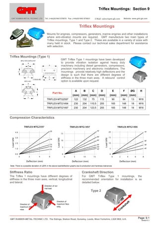
- 1. Triflex Mountings: Section 9 GMT RUBBER-METAL-TECHNIC LTD Tel: (+44)(0)1943 870670 Fax: (+44)(0)1943 870631 Website: www.gmt.gb.com Triflex Mountings Mounts for engines, compressors, generators, marine engines and other installations where anti-vibration mounts are required. GMT manufacture two main types of Triflex mountings, Type 1 and Type 2. These are available in a variety of sizes with many held in stock. Please contact our technical sales department for assistance with selection. Triflex Mountings (Type 1) GMT Triflex Type 1 mountings have been developed to provide vibration isolation against heavy duty machinery including diesel generators, compressors, precision machinery and electronic installations. The mountings provide relatively high deflections and the design is such that there are different degrees of stiffness in the three main axes. A rebound control option is available upon request. MTG1494 & MTG2597 B A C H F E 2 HOLES ØG D MTG1497 B H A C Part No. F B C D E (mm) (mm) (mm) (mm) F (mm) ØG H (mm) (mm) TRIFLEX-MTG2597 122 132 75 115 90 84 13 M16 TRIFLEX-MTG1494 230 204 110.5 205 165 148 18 M16 TRIFLEX-MTG1497 230 204 123.5 205 165 148 18 M16 Compression Characteristics TRIFLEX-MTG2597 TRIFLEX-MTG1497 70° 05 4.0 04 2.0 03 02 1.0 65° 10 60° 5 55° 50° 45° 01 0.0 0 0 2 4 6 Load (kN) 3.0 70° 20 15 Load (kN) Load (kN) TRIFLEX-MTG1494 15 60° 10 55° 45° 5 0 0 Deflection (mm) 5 10 15 0 Deflection (mm) 2 4 6 8 Deflection (mm) Note: There is a possible deviation of ±20% in the above load/deflection graphs due to production and hardness tolerances Stiffness Ratio Crankshaft Direction The Triflex 1 mountings have different degrees of stiffness in the three main axes, vertical, longitudinal and lateral. For GMT Triflex Type 1 mountings, the recommended orientation for installation is as detailed below: Direction of normal load Direction of maximum stiffness Direction of maximum flexibility Type 2 af an Cr h ks GMT RUBBER-METAL-TECHNIC LTD. The Sidings, Station Road, Guiseley, Leeds, West Yorkshire, LS20 8BX, U.K. t Page: 9.1 Version 9.1
- 2. Triflex Mountings Cont’d: Section 9 GMT RUBBER-METAL-TECHNIC LTD Tel: (+44)(0)1943 870670 Fax: (+44)(0)1943 870631 Website: www.gmt.gb.com Triflex Mountings (Type 2) GMT Triflex Type 2 mountings have been developed for the insulation of static and mobile machines and engines. Mounts have DNV type approval for the flexible mounting of propulsion and auxiliary machinery. Applications include generators, marine engines, compressors, fans and pumps. The mountings provide different degrees of stiffness in the three main axes and also have integrated rebound control. F C A Part No. B C D E F G H (mm) (mm) (mm) (mm) (mm) (mm) (mm) G 60 40 80 100 11x14 11x14 M12 184 75 50 103.5 140 20x13 20x13 M16 TRIFLEX-MTG1088 E A H B 120 TRIFLEX-MTG1087 D TRIFLEX-MTG1086 230 112 70 133.0 182 26x18 26x18 M20 Compression Characteristics TRIFLEX-MTG1087 TRIFLEX-MTG1086 TRIFLEX-MTG1088 65° 65° 65° 3.0 0.6 45° 0.4 55° 2.0 45° 1.0 35° Load (kN) 8.0 55° Load (kN) Load (kN) 0.8 0.2 55° 6.0 45° 4.0 2.0 0.0 0.0 0 1 2 3 4 0.0 0 1 Deflection (mm) 2 3 4 5 0 1 Deflection (mm) 2 3 4 5 6 Deflection (mm) Note: There is a possible deviation of ±20% in the above load/deflection graphs due to production and hardness Stiffness Ratio Crankshaft Direction The design of the Triflex 2 mountings provides different degrees of stiffness in the three main axes, vertical, longitudinal and lateral. For GMT Triflex Type 2 mountings, the recommended orientation for installation is as detailed below: . Vertical Stiffness Type 2 Direction of normal load ft 2.5 x Vertical Stiffness 0.75 x Vertical Stiffness nk ra Direction of maximum flexibility Direction of maximum stiffness a sh C Adjustable Studs GMT Adjustable studs are available in 3 main sizes and are suitable for use with the Triflex mounting range where height adjustment is required. A Part No. A L ØD (mm) (mm) STUD-M2196 M12 x 1.75 100 44.0 STUD-M2197 M16 x 2.0 110 56.0 STUD-M2198 M20 x 2.5 150 72.0 ØD GMT RUBBER-METAL-TECHNIC LTD. The Sidings, Station Road, Guiseley, Leeds, West Yorkshire, LS20 8BX, U.K. Page: 9.2 Version 9.1
- 3. Triflex Mountings Cont’d: Section 9 GMT RUBBER-METAL-TECHNIC LTD Tel: (+44)(0)1943 870670 Fax: (+44)(0)1943 870631 Website: www.gmt.gb.com Large Triflex Mountings GMT Large Triflex Mountings have been developed for the insulation of static and mobile machines and engines for the load range 8kN to 20kN. Applications include medium/ large marine engines and generators. The mounts provide different degrees of stiffness in the three main axes and also have integrated rebound control. These parts can be manufactured and supplied with or without the adjustable top bolt and with or without the four tie down bolts. TRIFLEX-MTG2019 TRIFLEX-MTG2218 6.0 14.0 111.0 190.0 270.0 CRS 330.0 M24x3.0 111.0 178.0 RANGE OF ADJUSTMENT Ø22.0 220.0 270.0 CRS 330.0 M24 Ø22.0 135.0 CRS 135.0 CRS 190.0 Compression Characteristics 15 50° 10 5 70° 8 Load (kN) Load (kN) 60° 70° 20 TRIFLEX-MTG2019/MTG2218 LATERAL 60° 6 50° 4 2 0 2 4 Deflection (mm) 6 60° 70° 25 20 15 50° 10 5 0 0 0 TRIFLEX-MTG2019/MTG2218 LONGITUDINAL Load (kN) TRIFLEX-MTG2019/MTG2218 VERTICAL 0.0 0.5 1.0 1.5 2.0 2.5 Deflection (mm) 0 2 4 6 Deflection (mm) Note: There is a possible deviation of ±20% in the above load/deflection graphs due to production and hardness tolerances GMT RUBBER-METAL-TECHNIC LTD. The Sidings, Station Road, Guiseley, Leeds, West Yorkshire, LS20 8BX, U.K. Page: 9.3 Version 9.1