2. 2
OEM Performance and Coverage
The unique split-in-half flex element and reversible hubs
significantly reduce total costs by reducing inventory and
assembly time.
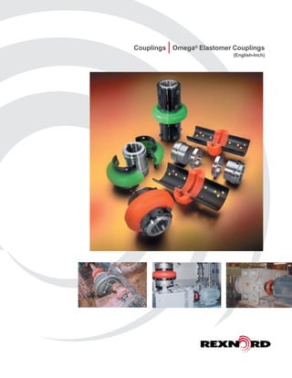
Rexnord Omega couplings are non-lubricated, material-flexing
couplings utilizing a specially formulated polyurethane material
engineered for maximum durabilty, strength and fatigue
resistance.
The Rex Omega HSU coupling (green) is specifically designed
for hot and humid conditions.
Rexnord is the leading coupling provider in the industry with a
full-line of available solutions supported by trained customer
service and application engineering professionals focused only
on our coupling product line. For more information, contact
your local Rexnord account executive.
Omega® Elastomeric Couplings
Features and Benefits
• Split-in-half flex element
design for simplified
assembly and disassembly
• Interchangeable hubs allow
for reduced inventory
• High misalignment capacity
accommodates unavoidable
misalignment with low
reactionary forces
• Torsionally soft flex
element cushions shock
loads and vibration
extending equipment life
• Polyurethane flex element
does not require lubrication
• Polyurethane-to-metal
bond eliminates assembly
and slippage problems
associated with mechanically
clamped designs
• Our selection software
makes choosing the
right coupling a snap
• Rexnord field specialists are
locally based experts available
to support key end-users
• The Rexnord Omega
HSU coupling (green) is
specifically designed for hot
and humid environments.
In addition, the HSU material
performs well in caustic
and acidic environments.
Consult Rexnord engineering
for your application.
Rexnord Omega couplings operate in
either horizontal or vertical applications
without any additional components.
Ease of installation, ease of
maintenance, and visual inspection
make these couplings a must for
many applications such as this mash
cooker in a brewery.Never operate
coupling without an OSHA approved guard.
Polyurethane-to-Metal Bond
Torsionally Soft
Flex Element
Radial Bolting
Interchangeable Hubs
Split-in-Half Design
DESCRIPTION PAGE
Installation and Misalignment Ratings 3
Standard Close Coupled Design 4 – 5
Spacer Design 6 – 7
Spacing Options and Extended Spacer Design 8 – 9
Mill Motor Design 10
Special Designs 11
Selection 12–14
Bore Specifications and Finished Stock Bore Hubs 15
Ordering 16
Table Of Contents
3. 3
Installation
Tested Tough
Mount one hub to shaft, leave other
hub loose for adjustment of spacing.
Place half of the Rexnord® Omega®
element around hubs and secure with
self-locking capscrews. Omega
element will space the other hub.
Now secure the other hub.
Mount other half of the Omega
element. Tighten all capscrews to
recommended torques below and
you’re done! Refer to the installation
instruction for further details.
Rigorous testing demonstrates that
the Rexnord Omega coupling protects
connected equipment from the damaging
effects of misalignment, vibration and
gross overload. Where other coupling
designs might allow equipment
damage, the super flexible element of
Rexnord Omega couplings minimizes
the reactionary forces on equipment
bearings under severe misalignment
conditions and reduces the effects
of excessive shock overloads.
- Important-
Recommended Capscrew Tourque
For Proper Installation
Severe static testing (5 × rating)
shows element flexibility, rugged
design and positive adhesive
bond to the metal shoes.
Demonstrates coupling’s ability to
accept severe misalignment.
4°
3°
2°
1°
0°
1/32 1/16 3/32 1/8 3/16
Size 2-10
Size 20-50
Size 60-80
Size 100-140
OMEGA
HUB OMEGA
HUB
Parallel
Parallel
OMEGA
HUB
OMEGA
HUB
Angular
Angular
Omega® Coupling
Allowable Misalignment
Coupling
Size
Torque - Dry
In. Lbs. Ft. Lbs.
2
204 17
3
4
5
10
20
360 30
30
40
50
60
900 7570
80
100
3240 270
120
140 7080 590
Note:
Any combination of parallel and angular misalignment which falls under the triangle
will not cause a premature fatigue failure of the flexible element in normal use.
NOTE: Capscrews have self locking patches which
should not be reused more than twice. Capscrews can
be further used if a thread locking adhesive is applied.
Do NOT Lubricate Capscrew Threads
Important Note:
Coupling alignment is directly related to
smooth, efficient equipment operation. Care
should be taken for best possible alignment.
4. Note: Dimensions subject to change. Certified dimensions of ordered material furnished on request.4
With Straight Bore Hubs
(OUT) (OUT) (IN) (IN)
D
B B
F
(HUBS OUTBOARD)
A
C B B
F
(HUBS INBOARD)
C
Note: Hub/shoulder design
varies per coupling
size. Consult Rexnord
for specific size
assembly drawings.
Omega
Coupling
Size
Recom.
Max.
Bore
(In.)
Continuous
HP/100
RPM
Continuous
Torque
(In. Lbs.)
Max.
RPM
Dimensions In Inches
Weight
(Lb.)A B
C
D
F
(In.) (Out) (In.) (Out)
E2 1.13 0.30 190 7500 3.5 0.94 1.34 1.90 1.85 3.22 3.78 1.2
E3 1.38 0.58 365 7500 4.00 1.50 0.81 1.31 2.32 3.81 4.31 2.4
E4 1.63 0.88 550 7500 4.56 1.69 0.44 1.31 2.60 3.81 4.69 3.0
E5 1.88 1.48 925 7500 5.38 1.75 0.81 1.81 3.13 4.31 5.31 5.4
E10 2.13 2.30 1450 7500 6.38 1.88 0.56 1.81 3.65 4.31 5.56 8.2
E20 2.38 3.65 2300 6600 7.25 2.06 0.50 2.38 4.48 4.62 6.50 13.0
E30 2.88 5.79 3650 5800 8.25 2.31 0.56 2.44 5.42 5.19 7.06 21
E40 3.38 8.85 5500 5000 9.50 2.50 0.56 2.68 6.63 5.56 7.68 35
E50 3.63 12.14 7650 4200 11.00 2.75 0.63 3.38 8.13 6.13 8.88 54
E60 4 19.84 12,500 3800 12.50 3.25 0.69 3.44 8.75 7.19 9.94 72
E70 4.5 35.12 22,125 3600 14.00 3.62 0.75 3.75 9.25 8.00 11.00 86
E80 6 62.7 39,500 2000 16.00 4.87 0.75 5.00 11.25 10.50 14.75 170
E100 6.75 135 85,050 1900 21.00 5.50 1.75 3.75 14.13 12.75 14.75 244
E120 7.5 270 170,100 1800 25.00 6.00 2.25 4.88 17.63 14.24 16.88 425
E140 11 540 340,200 1500 30.00 7.00 3.00 5.00 20.88 17.00 19.00 746
• Split-In-Half Flex Element
Allows disassembly and replacement without
disturbing hubs or connected equipment.
• Reversible Hubs
Accommodates different shaft spacing
requirements, and allows compression bushings
to be installed from either side of the hub.
Straight Bore Hubs QD Hubs and Bushings TAPER-LOCK® Hubs and Bushings
See page 14 for larger bore capacities with shallow keyways
8. 8
Shaft Spacing Possibilities
(Using Straight Bore Hubs)
Figure A
Both hubs mounted outboard
Figure B
One hub mounted inboard
One hub mounted outboard
Figure C
Both hubs mounted inward
Figure D
Figure E Figure F
(OUT) (OUT) (OUT) (IN)
(IN) (IN)
Note: Optional capscrew hole mounting positions
allow easy on-site adjustment to meet
various shaft spacing requirements.
Note: Shaft engagement should be equal to or
greater than .8 times shaft diameter.
100% shaft engagement is suggested for
compression bushed hubs.
The Rexnord® Omega® spacer coupling design (pages 6-7) provides clear space between hubs. There are no interfering center
members or spools which allows shaft spacing as small as 1
/4”; however, for such small spacings, use of the standard Omega coupling
would be recommended. The maximum shaft spacing for each coupling is shown of pages 6-7. Any ANSI, ISO or DIN spacing between
1
/4 inch and the maximum listed can be achieved without any additional parts. Hubs can be placed on the shafts as shown below.
Use one half of the flex element to establish shaft spacing and appropriate mounting position. Optional hole mounting positions
and reversible hubs allow adjustments as needed. Select the combination which most closely matches the dimensions
desired between shafts (Figure D). Drawings with specific mounting positions/dimensions are available from Rexnord.
Hubs can be flush with the shaft end (not shown), extended beyond the end of the shaft (Figure E) or recessed
behind the shaft end provided there is sufficient keyway engagement (Figure F). Special sleeve extensions
(see page 9) are available for spacing requirements in excess of those listed on pages 6-7.
“Adjustability”
9. Note: Dimensions subject to change. Certified dimensions of ordered material furnished on request. 9
Rexnord® Omega® extended spacer couplings are designed to connect equipment with shaft spacing requirements
beyond the Omega spacer coupling capabilities. They are ideal for applications with wide non-standard shaft
gaps, and can be an economic alternative to floating shaft couplings (i.e. stock pump applications).
Sleeve extensions (“SE”) are furnished in steel. They mount to regular Omega spacer elements (standard
elements for sizes E100 & E120) and cast iron or steel hubs – straight bore or compression bushed design.
By adjusting the hub/shaft engagement (see figures E & F on page 8) and spacer element mounting position,
the Omega extended spacer coupling can be utilized for many shaft spacing requirements.
Extended Spacer Coupling
C
Single Extension
C
Double Extension
agemO
recapS
eziS
.xaM
MPR
dradnatS
.xaM
MPR
dehctaM
ylbmessA
gnicapSmumixaM sehcnI–noisnemiD”C“–
sbuHBRHShtiW sbuHDQHhtiW sbuHLTHhtiW
thgieW
).bL(
ESenO
.xaM
tuohtiW
ES
enO
ES
owT
ES
.xaM
tuohtiW
ES
enO
ES
owT
ES
.xaM
tuohtiW
ES
enO
ES
owT
ES
R-3SE 0081 0063 00.5 00.7 00.9 — — — 83.5 83.7 83.9 2.1
R-4SE 0081 0063 00.5 00.7 00.9 65.5 65.7 65.9 83.5 83.7 83.9 4.1
R-5SE 0081 0063 00.5 00.7 00.9 60.5 60.7 60.9 83.5 83.7 83.9 5.1
R-01SE 0081 0063 00.5 00.7 00.9 94.5 94.7 94.9 52.5 52.7 52.9 6.1
02SE 0081 0063 00.7 57.9 05.21 69.6 17.9 64.21 57.6 05.9 52.21 7.3
03SE 0081 0063 00.7 57.9 05.21 44.6 79.8 27.11 05.6 52.9 00.21 5.4
04SE 0081 0063 00.7 57.9 05.21 47.5 32.8 89.01 00.6 57.8 05.11 3.5
05SE 0081 0013 00.7 57.9 05.21 42.6 37.8 84.11 00.6 57.8 05.11 0.8
06SE 0081 0082 57.9 83.41 00.91 86.7 13.21 39.61 57.8 83.31 00.81 8.02
07SE 0081 0062 57.9 31.51 05.02 27.6 01.21 74.71 43.7 27.21 90.81 6.43
08SE 0051 0081 57.9 83.51 00.12 67.4 93.01 10.61 48.6 73.21 00.81 2.64
001E 0051 0081 57.3 57.8 57.31 57.1 00.7 52.21 00.6 52.11 05.61 0.67
021E 0051 0081 88.4 31.01 83.51 47.1 47.6 47.11 31.7 31.21 31.71 3.18
041E 0021 0051 00.5 05.10 00.22 3.00 8.50 14.00 7.00 12.50 18.00 122.0
.dronxeRtlusnoc;elbaliavaerasnoisnetxehtgnelmotsucregnoL.sdnetfahshtiwhsulfdnadraobtuodetnuomsbuhhtiweranwohssgnicapsmumixaM
.gniredronehw”ylbmessAdehctaM“yficepS.gnitardeepsrehgihniatbootdehctamdnadenihcamylesicerpylbmessanoisnetxeeveels/buH
Ordering Information: When ordering, be sure to specify whether one of two sleeve
extensions are required. If custom length, specify distance between shaft ends.
• Optional sleeve extensions (“SE”)
An economical alternative to floating shaft couplings (i.e., stock pump applications).
Sleeve Extensions
11. Note: Dimensions subject to change. Certified dimensions of ordered material furnished on request. 11
Special Designs
Stainless
Steel
Rexnord® Omega® HSU Element
Hydrolytically Stable Urethane for superior resistance to hot and
humid conditions in addition to acidic and alkaline environments.
The Omega HSU element in interchangeable with existing hubs.
Rexnord® Omega® Positive Drive
Coupling
With interlocking drive fail safe requirements.
Rexnord® Omega® Keyless Hub/
Bushing Design
Several optional keyless Hub/Bushing designs are available
for increased bore end shaft gap requirements.
Rexnord® Omega® Stainless Steel
Element
Corrosion resistant 303/304 stainless steel shoes for severe
environments.
Stainless steel hubs also available.
Rexnord® Omega® Spline Bore Hub
1. Number of Teeth – Ex. 14T
2. Pitch Fraction – Ex. 12/24 Pitch
3. Pressure Angle – 30° P.A.
4. Type of Tooth Shape – Ex. Involute or Straight Side
5. Type of Root – Ex. Fillet or Flat Root
6. Tolerance – Ex. Class I thru VII
7. Type of Fit – Ex. Side Fit or Major Diameter Fit
Rexnord® Omega® Light Duty Element
Available in size E2LD only. Minimum O.D. (2.5”) for low
profile applications. Max torque rating of 100 In. Lbs.
12. 12
Selection Procedures
1. Determine HP/100RPM: HP/100 RPM = Horsepower x 100
RPM
2. Determine Service Factor:
Select the proper Service Factor from Table on page
13. If not listed, see Load Classification Table.
Remember to consider both driver and driven
equipment and temperature requirements.
3. Multiply HP/100 by the service factor to get equivalent HP/100 RPM.
4. Select the Coupling Size:
From Table 1, with a rating equal to or greater than the
equivalent HP/100 RPM determined in Step 3.
5. Check Limiting Conditions:
Be sure that the operating speed of the coupling does
not exceed maximum RPM listed on page 4-7.
6. Select Desired Hub Type:
Select desired hub type and check maximum
allowable coupling bore on page 14.
OR
1. Determine Operating Torque:
(
63,000 x HP
) RPM
2. Multiply by Service Factor
Select the proper Service Factor from Table on page 13.
3. Select the Coupling Size:
Select coupling size from Table 2 with a capacity
equal to or greater than determined in Step 2.
4. Follow Steps 5 & 6 Above
Service Factors
Service Factors are a means of classifying different equipment and applications into various load classifications.
Due to variations in application of equipment, service factors are used to adjust equipment ratings to accommodate
for variable loading conditions. This is a general guide. More specific factors are given on page 13.
Continuous service and running loads vary only slightly. 1.0
Torque loading varies during operation of the equipment. 1.5
Torque loading varies during operation, frequent stop/
start cycles are encountered.
2.0
For shock loading and substantial torque variations. 2.5
For heavy shock loading or light reversing drives. 3.0
Reversing torque loads do not necessarily mean reversal
of rotation. Depending upon severity of torque reversal,
such loads must be classified between “medium” and
“extreme.”
Consult Rexnord
Load Classifications Service Factors
The service factor adjustment
for high temperature is in
addition to the service factor
consideration for the driver and
driven equipment. However, if
high temperatures are typical for
a specific application, maximum
temperature consideration is
incorporated into the “typical”
service factor listing on page 13.
i.e., steel mill runout tables.
Table 1
Size Equivalent
HP/100 RPMStandard Spacer
E2 ES2 0.3
E3 ES3 0.58
E4 ES4 0.88
E5 ES5 1.48
E10 ES10 2.3
E20 ES20 3.65
E30 ES30 5.79
E40 ES40 8.85
E50 ES50 12.14
E60 ES60 19.84
E70 ES70 35.12
E80 ES80 62.7
E100 NA 135
E120 NA 270
E140 NA 540
Table 2
Torque Capacity
Size
Continuous
Torque
(In. Lbs.)
Size
Continuous
Torque
(In. Lbs.)
2 190 40 5,500
3 365 50 7,650
4 550 60 12,500
5 925 70 22,125
10 1,450 80 39,500
20 2,300 100 85,050
30 3,650 120 170,100
140 340,200
Omega® Element
Temperature Range (Ambient)
-40°F +200°F
to
-40°C +93°C
High Temperature
Service Factor Adjustment*
Ambient Temp. S.F. Adjust.
+150°F (66°C) 0.025
+165°F (74°C) 0.05
+180°F (82°C) 0.75
+200°F (93°C) 1
*Added to application service factor
16. 16
Ordering Instructions
1. Drawing of HUB showing complete
bore and keyway details.
— OR —
2. Drawing of SHAFT with dimensions shown
below, allowing Rexnord to bore hubs to suit.
(LD) Large Diameter, Specify in Decimals.
(S) Length of Taper, Measure parallel to Shaft centerline.
(T) Taper per Foot, Difference in Diameter in one foot length.
(P) Clearance space for drawing Hub up on tapered shaft.
Usually 1
/8” or 1
/4”, depending on shaft size and taper.
Keyway: Width, Depth.
Note: Specify if keyway is parallel to Taper or if parallel to shaft
center line.
Specify depth at larger diameter of Taper if
keyway is parallel to shaft center line.
With connected equipment in fixed position, the
following additional information is necessary:
Dimensions “V” and “X” must be given when one or both
connected machines are fixed on their bases. Advise if
dimension “X” is fixed, or if variable between what limits.
A fixed “X” dimension may require altered or special coupling
hubs. Often the straight bored hub can be positioned on its shaft
allowing the use of a standard coupling. See illustrations below.
Consult A.G.M.A. Standard 9002 “Taper Bores
for Flexible Couplings” for new applications.
Tapered Bores
HUB SHORTENEDSHAFT PROJECTSHUB COUNTERBORED
AVAILABLE
LENGTH OF
SHAFTKEYWAY
C
XVES
T
E
NLDN
W
PP
HUB SHORTENEDSHAFT PROJECTSHUB COUNTERBORED
AVAILABLE
LENGTH OF
SHAFTKEYWAY
C
XVES
T
E
NLDN
W
PP
HUB SHORTENEDSHAFT PROJECTSHUB COUNTERBORED
AVAILABLE
LENGTH OF
SHAFTKEYWAY
C
XVES
T
E
NLDN
W
PP
Standard and Spacer Couplings
When ordering a complete coupling, specify size/type of element and hubs (two hubs per complete coupling) options include:
Element
[E2 – E140] standard (close coupled)
[ES2-R – ES80] spacer
Hub
[2HRB – 140HRB] straight hub-rough bore
[2HSB – 60HSB] straight hub-stock bore (specify bore size from table on page 15)
[2HCB – 140HCB] straight hub-custom bore (specify bore and keyway)
[4HQD – 140HQD] hub-QD (bushing not included)
[3HTL – 140HTL] hub-TAPER-LOCK® (bushing not included)
[10HMM – 140HMM] straight hub-mill motor (specify mill motor number, rough or custom bore)
Order Example:
Complete E50 standard (close coupled) coupling with one finished bore 21
/8”hub w/standard keyway and one QD hub less bushing.
Order description:
1 ea. E50 element
1 ea. 50HSB – 21
/8” – std.
1 ea. 50 HQD – steel