1. Highway Surveying Manual Page 5-1
January 2005
Chapter 5 Public Lands Survey System
5-01 History and Background
The following information is in reference from the U.S. Department of the Interior,
Bureau of Land Management (BLM) book titled: “Manual of Surveying Instructions”.
Refer to the BLM Manual for additional information not used in this chapter.
The Public Lands Survey System (PLSS) was originally set up to sell the lands acquired
by the U.S. Government in the Northwest Territory (Ohio, Indiana, Illinois, Michigan,
and Wisconsin). It was so successful that it was used later to sell land in the Louisiana
Purchase, Oregon Territory, Mexican Cession, and Alaska.
The system designates land location east or west of a principal meridian and north or
south of a base line. In the state of Washington, the principal meridian is known as the
Willamette Meridian (abbreviated as W.M. in legal descriptions). The principal meridian
runs north and south from a stone monument established in 1851 located in Portland,
Oregon. This stone monument is also on the east-west base line (the Willamette Base
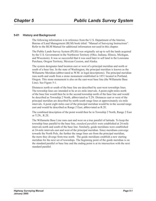
Line). See Figure 5-1.
Distances north or south of the base line are described by east-west townships lines.
The township lines are intended to be at six-mile intervals. A point eight miles north
of the base line would then be in the second township north of the base line and would
be described as Township 2 North, abbreviated as T.2N. Distances east or west of the
principal meridian are described by north-south range lines at approximately six-mile
intervals. A point eight miles east of the principal meridian would be in the second range
east and would be described as Range 2 East, abbreviated as R.2E.
The combined description of the point would then be in Township 2 North, Range 2 East
or T.2N., R.2E.
The Willamette Base Line runs east and west on a true parallel of latitude. To keep the
township lines parallel to the base line, standard parallels were established at 24-mile
intervals north and south of the base line. Similarly, guide meridians were established
at 24-mile intervals east and west of the principal meridian. Since meridians converge
towards the North Pole, the further the range lines are from the principal meridian,
the more they diverge from true north. The guide meridians establish a new starting
meridian for the next set of townships. The beginning point of the guide meridian is on
the standard parallel or base line and the ending point is at its intersection with the next
standard parallel.
2. Page 5-2 Highway Surveying Manual
January 2005
Public Lands Survey System
Thus, on the base line and on a standard parallel, there will be a convergence offset
between the guide meridian to the south and the one to the north.
Willamette Stone
established June 4, 1851
Beginning here the Willamette Meridian was
established running north to Puget Sound and
south to the California border and the base line was
established running east to the Idaho border and
west to the Pacific Ocean.
From these surveyed lines the lands of the
northwest were divided into townships six miles
square beginning at the Willamette base line
numbering north or south and given a range
beginning at the Willamette Meridian numbering
east and west. Each full township is divided into
36 sections of land one mile square which are
numbered starting at the northeast corner of each
township as shown on the diagram.
Figure 5-1
The final result is a series of quadrangles bounded by meridians and parallels each
including 16 townships. See Figure 5-2.
5-02 Township Subdivision
Each township, approximately 6 miles on a side, was further divided into 36 sections and
monuments were set at the section corners. Each section was intended to be 640 acres
or one square mile in area. Variations of angular and distance measurements may vary
slightly from today’s measurements due to a myriad of factors. The physical location
of original monuments set is the true corner even if the theoretical position places it in a
very different position.
The numbering of the sections starts at the northeast corner of the township with Section
1 (Figure 5-3) and progresses westerly to Section 6 at the northwest corner of the
township.
Section 7 is south of Section 6 and the numbering then increases to the east with Section
12 directly south of Section 1. The numbering continues, alternating between increasing
to the east and increasing to the west, then to Section 36 in the southeast corner of the
township.
3. Highway Surveying Manual Page 5-3
January 2005
Public Lands Survey System
Principal Meridian, Base Line,
Standard Parallels and Guide Meridians
Figure 5-2.
Township Grid Section Grid
Figure 5-3 Figure 5-4
4. Page 5-4 Highway Surveying Manual
January 2005
Public Lands Survey System
Nomenclature for Portions of a Section
Figure 5-5
The dimensions of the sections were measured in chains and links. A chain of 100 links
is equal to 66 feet and a link is 7.92 inches. A section was intended to be 80 chains (one
mile) on each side.
5-03 Section Subdivision
Along with the section corner monuments, quarter corner monuments were set at the
halfway point on each side of a section. Thus, the 80 chain sides were theoretically
divided into 40 chain (1 /2 mile) segments. The original surveyors were not instructed to
set a monument at the theoretical center of section (where the lines connecting quarter
corners would inter-sect).
Each quarter of a section ( 1 /4 square mile) was theoretically 160 acres and could be
divided as shown in Figures 5-4 through 5-7.
Certain areas of land were not available for sale and the boundaries of the Public Lands
Survey System (PLSS) stopped at the edge of these areas. Some examples are:
• Indian reservations (IR)
• Donation land claims (DLC)
• Military reservations (MR).
• Some bodies of water
• Mining claims
To establish where the PLSS lines intersected the boundary line, auxiliary corners were
set, known as witness corners (WC).
5. Highway Surveying Manual Page 5-5
January 2005
Public Lands Survey System
The Surveyor General instructed the surveyors to commence surveying the sections
within the Townships by starting at the southeast corner of Section 36. They were to
proceed in a northerly direction setting the quarter and section corners as they went. All
of the north-south section lines were to be established from south to north moving east
to west. These are called Meridional Section Lines. The east west section lines were
established from West to East between the meridional section lines as the surveyors
worked their way north. These are called Latitudinal Section Lines. In this manner of
section line establishment, all of the measuring error was placed in the north and west
tiers of the township. This meant that the sections along the north and west lines of any
township are irregular sections and have more or less than the standard 640 acre area for
a regular section.
The section was broken down into regular quarter sections as much as possible and the
irregular pieces were called Government Lots (GL). This same system was also used
where the section line intersected one of the reserved areas listed above (IR, MR, DLC,
etc.). See Figure 5-8.
In summary, a section is approximately one square mile unless it lies on the north or
west side of a township or abuts one of the areas not available for sale. In these irregular
sections, there will be a mixture of regular quarter sections and Government Lots.
Showing areas in acres Showing calculated distances in chains
Example of Subdivision of Section 6
Figure 5-6
6. Page 5-6 Highway Surveying Manual
January 2005
Public Lands Survey System
Section 6 has Fractional Measurements of more or less than
20 chains on lines marked “Frac”
Fractional Measurements
Figure 5-7
Example of Government Lots in Irregular Sections
Figure 5-8
7. Highway Surveying Manual Page 5-7
January 2005
Public Lands Survey System
The surveyors used whatever was available as a monument. Where wood was available,
they used a post, usually 4” × 4”, marked on the side with the section designation. Where
wood was not available, they used stone monuments, dug pits, built mounds, or buried a
quart of charcoal. See Figure 5-9.
Since the original surveys, government agencies and private surveyors have perpetuated
many of the original monuments with more permanent markers.
In addition to monumenting the corners, the original surveyors also marked trees along
the boundaries when available. These are known as line trees and were blazed or hacked
with an axe. See Figure 5-10.
Similarly, if trees were near a corner, the surveyor recorded the distance and bearing of
the tree, removed a piece of bark, and scribed on the living wood tissue.
Often, the bearing tree (BT) had been cut down but the stump may still be there. Since the
section corner was also the meeting place of four property lines, it was frequently used as
a fence corner. By using the recorded bearings and distances from bearing trees or other
reference points, it is possible to verify if an old fence corner was placed at the location
of the original section corner. See Figures 5-11 and 12.
In summary, almost anything might have been used to replace an old corner. The problem
is then to confirm that what is found at the supposed site of the corner is at the exact
location of the old corner and not just in the vicinity.
If there is a record in a survey book that some surveyor replaced the original corner (for
example, “a rotten post scribed with proper markings”) with an iron pipe, the problem
is then to determine if the iron pipe that is found is the same one that was set. If it is
possible to measure from other reference points and check the distances, then it is
reasonable to accept the pipe as a replacement of the original corner. However, if there
is no record of the replacement, the fact that there is an iron pipe does not automatically
make it the corner. Any monument is subject to dispute and it is necessary to prove the
position of anything other than the original corner. If the corner (or its replacement) is
missing, the corner may be either “lost” or “obliterated.” An obliterated corner is one that
has been destroyed but whose position can be reestablished from other recorded reference
points nearby.
A lost corner is one where all evidence of its location is gone. The location can be
reestablished by rerunning the original survey. A corner is not considered lost if it has
been assigned a coordinate using the Washington Coordinate System of 1983 (WCS83).
5-04 Restoring Lost or Obliterated Corners
Restoration of a lost or obliterated corner must be replaced by a Professional Land
Surveyor See Chapter 16.
8. Page 5-8 Highway Surveying Manual
January 2005
Public Lands Survey System
Corner Monuments of the Public Land Surveys
Figure 5-9.
9. Highway Surveying Manual Page 5-9
January 2005
Public Lands Survey System
Marks Found on a Line Tree may be a Blaze, a Hack, or Both
Line Tree
Figure 5-10
The original marks are preserved and appear in reverse and relief on the overgrowth
Old Bearing Tree with Overgrowth Removed
Figure 5-11
10. Page 5-10 Highway Surveying Manual
January 2005
Public Lands Survey System
The position for a corner of the public land surveys may be recovered
by reference to the recorded bearing trees or bearing objects
Bearing Objects
Figure 5-12