Lafarge Process Kit - Air flow rate - Anemometer- duck out….pdf
•
0 likes•25 views

instructions

Recommended
Recommended
More Related Content
Similar to Lafarge Process Kit - Air flow rate - Anemometer- duck out….pdf
Similar to Lafarge Process Kit - Air flow rate - Anemometer- duck out….pdf (12)
More from Mario Charlin
More from Mario Charlin (20)
Recently uploaded
Recently uploaded (20)
Lafarge Process Kit - Air flow rate - Anemometer- duck out….pdf
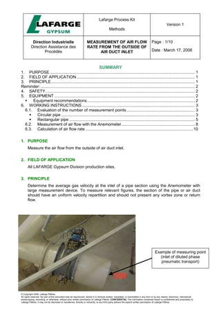
- 1. Lafarge Process Kit Methods Version 1 Direction Industrielle Direction Assistance des Procédés MEASUREMENT OF AIR FLOW RATE FROM THE OUTSIDE OF AIR DUCT INLET Page : 1/10 Date : March 17, 2006 © Copyright 2006, Lafarge Plâtres All rights reserved. No part of this document may be reproduced, stored in a retrieval system, translated, or transmitted in any form or by any means, electronic, mechanical, photocopying, recording, or otherwise, without prior written permission of Lafarge Plâtres. CONFIDENTIAL The information contained herein is confidential and proprietary to Lafarge Plâtres. It may not be disclosed or transferred, directly or indirectly, to any third party without the explicit written permission of Lafarge Plâtres SUMMARY 1. PURPOSE............................................................................................................................. 1 2. FIELD OF APPLICATION...................................................................................................... 1 3. PRINCIPLE............................................................................................................................ 1 Reminder:..................................................................................................................................... 2 4. SAFETY................................................................................................................................. 2 5. EQUIPMENT ......................................................................................................................... 2 Equipment recommendations............................................................................................. 2 6. WORKING INSTRUCTIONS ................................................................................................. 3 6.1. Evaluation of the number of measurement points........................................................... 3 Circular pipe ................................................................................................................... 3 Rectangular pipe ............................................................................................................ 5 6.2. Measurement of air flow with the Anemometer............................................................... 8 6.3. Calculation of air flow rate .............................................................................................10 1. PURPOSE Measure the air flow from the outside of air duct inlet. 2. FIELD OF APPLICATION All LAFARGE Gypsum Division production sites. 3. PRINCIPLE Determine the average gas velocity at the inlet of a pipe section using the Anemometer with large measurement device. To measure relevant figures, the section of the pipe or air duct should have an uniform velocity repartition and should not present any vortex zone or return flow. Example of measuring point (inlet of diluted phase pneumatic transport)
- 2. Lafarge Process Kit Methods Version 1 Direction Industrielle Direction Assistance des Procédés MEASUREMENT OF AIR FLOW RATE FROM THE OUTSIDE OF AIR DUCT INLET Page : 2/10 Date : March 17, 2006 © Copyright 2006, Lafarge Plâtres All rights reserved. No part of this document may be reproduced, stored in a retrieval system, translated, or transmitted in any form or by any means, electronic, mechanical, photocopying, recording, or otherwise, without prior written permission of Lafarge Plâtres. CONFIDENTIAL The information contained herein is confidential and proprietary to Lafarge Plâtres. It may not be disclosed or transferred, directly or indirectly, to any third party without the explicit written permission of Lafarge Plâtres Reminder: - Do not use the Anemometer in a corrosive and dusty environment. 4. SAFETY For the measurement of air flow, the technician in charge of the test must wear safety gloves. 5. EQUIPMENT Equipment recommendations Equipment Supplier Price estimation Macro measuring sensor (Diam.: 80mm) SCHILTNECHT (Distributor: MESUREUR France) 1300 Euros
- 3. Lafarge Process Kit Methods Version 1 Direction Industrielle Direction Assistance des Procédés MEASUREMENT OF AIR FLOW RATE FROM THE OUTSIDE OF AIR DUCT INLET Page : 3/10 Date : March 17, 2006 © Copyright 2006, Lafarge Plâtres All rights reserved. No part of this document may be reproduced, stored in a retrieval system, translated, or transmitted in any form or by any means, electronic, mechanical, photocopying, recording, or otherwise, without prior written permission of Lafarge Plâtres. CONFIDENTIAL The information contained herein is confidential and proprietary to Lafarge Plâtres. It may not be disclosed or transferred, directly or indirectly, to any third party without the explicit written permission of Lafarge Plâtres MiniAir 2 Display SCHILTNECHT (Distributor: MESUREUR France) 900 Euros 6. WORKING INSTRUCTIONS 6.1. Evaluation of the number of measurement points Circular pipe The method to follow is the “Log-Tchebycheff method” : • “n” is the number of measurement points per radius (total number of points = 2n) • “i” appoints one measurement point (1 ≤ i ≤ 2n) diameter 'D 1st radius 2nd radius i 1 Y1 2n Yi Y2n There is n measurement points per radius and thus 2n measurement points per diameter. Those points are symmetric to each other from the center of the pipe. There’s no measurement on the center of the pipe. “Yi” is calculated as per the equation : Yi = Ci x D using the table presented here under. Due to the symmetry from the center of the pipe : Ci+ C2n+1-i = 1 n 1 st radius 2 nd radius 3 C1 = 0.0320 C2 = 0.1375 C3 = 0.3125 C6 = 0.9680 C5 = 0.8625 C4 = 0.6875 4 C1 = 0.0240 C2 = 0.1000 C3 = 0.1940 C4 = 0.3345 C1 = 0.9760 C2 = 0.9000 C3 = 0.8060 C4 = 0.6655
- 4. Lafarge Process Kit Methods Version 1 Direction Industrielle Direction Assistance des Procédés MEASUREMENT OF AIR FLOW RATE FROM THE OUTSIDE OF AIR DUCT INLET Page : 4/10 Date : March 17, 2006 © Copyright 2006, Lafarge Plâtres All rights reserved. No part of this document may be reproduced, stored in a retrieval system, translated, or transmitted in any form or by any means, electronic, mechanical, photocopying, recording, or otherwise, without prior written permission of Lafarge Plâtres. CONFIDENTIAL The information contained herein is confidential and proprietary to Lafarge Plâtres. It may not be disclosed or transferred, directly or indirectly, to any third party without the explicit written permission of Lafarge Plâtres 5 C1 = 0.0240 C2 = 0.1000 C3 = 0.1940 C4 = 0.3345 C4 = 0.3565 C1 = 0.0240 C2 = 0.1000 C3 = 0.1940 C4 = 0.3345 C4 = 0.6435 Example : n= 3 with a 300 mm pipe. In that case the total measurement points is 6 (Y1 to Y6). The hereunder table presents the calculation results : 1 st radius 2 nd radius i Ci Yi (mm) i Ci Yi (mm) 1 C1 = 0.0320 10 6 C6 = 0.9680 290 2 C2 = 0.1375 41 5 C5 = 0.8625 259 3 C3 = 0.3125 94 4 C4 = 0.6875 206 D = 300 mm Y1 = 10 Y2 = 41 Y3 = 94 Y4 = 206 Y5 = 259 Y6=290 1 2 3 4 5 6
- 5. Lafarge Process Kit Methods Version 1 Direction Industrielle Direction Assistance des Procédés MEASUREMENT OF AIR FLOW RATE FROM THE OUTSIDE OF AIR DUCT INLET Page : 5/10 Date : March 17, 2006 © Copyright 2006, Lafarge Plâtres All rights reserved. No part of this document may be reproduced, stored in a retrieval system, translated, or transmitted in any form or by any means, electronic, mechanical, photocopying, recording, or otherwise, without prior written permission of Lafarge Plâtres. CONFIDENTIAL The information contained herein is confidential and proprietary to Lafarge Plâtres. It may not be disclosed or transferred, directly or indirectly, to any third party without the explicit written permission of Lafarge Plâtres Rectangular pipe The equal areas are represented on the drawing here under : L/2n l/2n l n points N p o i n t s L • “N” is the number of measurement points on the length “L”. • “n” is the number of measurement points on the width “l”. The number of equal areas is : N x n The smaller distance from one measuring point to the wall is n 2 L for the length. The smaller distance from one measuring point to the wall is n 2 l for the width. The following tables are presenting some examples for the values of : N, n, n 2 L , n 2 l . For different square pipes : 1 l L = and for different rectangular pipes : 1 l L
- 6. Lafarge Process Kit Methods Version 1 Direction Industrielle Direction Assistance des Procédés MEASUREMENT OF AIR FLOW RATE FROM THE OUTSIDE OF AIR DUCT INLET Page : 6/10 Date : March 17, 2006 © Copyright 2006, Lafarge Plâtres All rights reserved. No part of this document may be reproduced, stored in a retrieval system, translated, or transmitted in any form or by any means, electronic, mechanical, photocopying, recording, or otherwise, without prior written permission of Lafarge Plâtres. CONFIDENTIAL The information contained herein is confidential and proprietary to Lafarge Plâtres. It may not be disclosed or transferred, directly or indirectly, to any third party without the explicit written permission of Lafarge Plâtres For a square area 1 l L = L (m) N L/2n (cm) l (m) n l/2n (cm) 0.5 2 12.5 0.5 2 12.5 1.0 4 12.5 1.0 4 12.5 1.5 5 15.0 1.5 5 15.0 2.0 6 16.7 2.0 6 16.7 2.5 7 17.9 2.5 7 17.9 3.0 8 18.8 3.0 8 18.8 For a rectangular area 5 . 1 l L = L (m) N L/2n (cm) l (m) n l/2n (cm) 0.75 3 12.5 0.5 2 12.5 1.50 5 15.0 1.0 4 12.5 2.25 7 16.1 1.5 5 15.0 3.00 8 18.8 2.0 6 16.7 3.75 8 23.4 2.5 7 17.9 The curve here under is a resume of those results : Number of measuring points as a function of L and l 0 1 2 3 4 5 6 7 8 9 0 0.5 1 1.5 2 2.5 3 3.5 4 4.5 5 L or l (m) N or n
- 7. Lafarge Process Kit Methods Version 1 Direction Industrielle Direction Assistance des Procédés MEASUREMENT OF AIR FLOW RATE FROM THE OUTSIDE OF AIR DUCT INLET Page : 7/10 Date : March 17, 2006 © Copyright 2006, Lafarge Plâtres All rights reserved. No part of this document may be reproduced, stored in a retrieval system, translated, or transmitted in any form or by any means, electronic, mechanical, photocopying, recording, or otherwise, without prior written permission of Lafarge Plâtres. CONFIDENTIAL The information contained herein is confidential and proprietary to Lafarge Plâtres. It may not be disclosed or transferred, directly or indirectly, to any third party without the explicit written permission of Lafarge Plâtres Example : Rectangular pipe length L = 50 cm width l = 40 cm Considering the curve here above : For the length : N = 2 For the width : n = 2 The distances between each point are presented in the table here under : L (m) 0.5 L (m) 0.4 N 2 n 2 L/2N (mm) 125 l/2n (mm) 100 The drawing for the measurement points location is the following one : 500 400 100 125 The total measurement points is : N x n = 4 x 4 = 16
- 8. Lafarge Process Kit Methods Version 1 Direction Industrielle Direction Assistance des Procédés MEASUREMENT OF AIR FLOW RATE FROM THE OUTSIDE OF AIR DUCT INLET Page : 8/10 Date : March 17, 2006 © Copyright 2006, Lafarge Plâtres All rights reserved. No part of this document may be reproduced, stored in a retrieval system, translated, or transmitted in any form or by any means, electronic, mechanical, photocopying, recording, or otherwise, without prior written permission of Lafarge Plâtres. CONFIDENTIAL The information contained herein is confidential and proprietary to Lafarge Plâtres. It may not be disclosed or transferred, directly or indirectly, to any third party without the explicit written permission of Lafarge Plâtres 6.2. Measurement of air flow with the Anemometer • Make sure that the arrow is in the correct direction of the air flow. • Measure the air flow rate. • Record the value from the display
- 9. Lafarge Process Kit Methods Version 1 Direction Industrielle Direction Assistance des Procédés MEASUREMENT OF AIR FLOW RATE FROM THE OUTSIDE OF AIR DUCT INLET Page : 9/10 Date : March 17, 2006 © Copyright 2006, Lafarge Plâtres All rights reserved. No part of this document may be reproduced, stored in a retrieval system, translated, or transmitted in any form or by any means, electronic, mechanical, photocopying, recording, or otherwise, without prior written permission of Lafarge Plâtres. CONFIDENTIAL The information contained herein is confidential and proprietary to Lafarge Plâtres. It may not be disclosed or transferred, directly or indirectly, to any third party without the explicit written permission of Lafarge Plâtres • Move the anemometer on the section pipe according to the defined location of measurement points.
- 10. Lafarge Process Kit Methods Version 1 Direction Industrielle Direction Assistance des Procédés MEASUREMENT OF AIR FLOW RATE FROM THE OUTSIDE OF AIR DUCT INLET Page : 10/10 Date : March 17, 2006 © Copyright 2006, Lafarge Plâtres All rights reserved. No part of this document may be reproduced, stored in a retrieval system, translated, or transmitted in any form or by any means, electronic, mechanical, photocopying, recording, or otherwise, without prior written permission of Lafarge Plâtres. CONFIDENTIAL The information contained herein is confidential and proprietary to Lafarge Plâtres. It may not be disclosed or transferred, directly or indirectly, to any third party without the explicit written permission of Lafarge Plâtres 6.3. Calculation of air flow rate To calculate the value of the air flow, use Thermicalc software as shown below: Key in the “yellow cells” the following figures: - Air flow rate (following the above test method) - Static pressure (following the method from the Lafarge Process Kit) - Dry temperature (following the method from the Lafarge Process Kit) - Wet Bulb temperature (following the method from the Lafarge Process Kit) - Diameter of the section - Atmospheric pressure (according to the location of the plant)