1. Zak Kershaw
66 3rd
Concession
Princeton, Ontario
N0J 1V0
May 23, 2016
Conestoga College
School of Engineering Technology
Cambridge, Ontario
N3H 4R7
Dear Sir:
The report entitled “Loader Arm Design” was prepared in accordance with the requirements of
the course Engineering Project and report, course code MECH3190/3200. This illustrates my
major design project.
The loader was analyzed in two worst case positions to ensure a safe design in its range of
motion.
The report has been prepared and written by myself. It has not been submitted to or graded by
any other academic institution.
Sincerely
Zak Kershaw
2. Mech 3190/3200 Report Loader Arm
Zak Kershaw
Loader Arm Design
Prepared by: Zak Kershaw
Prepared for: Rob Schaaf
3. Mech 3190/3200 Report Loader Arm
Zak Kershaw
Abstract
A loader arm mounted on an agricultural tractor is used in the lifting of manure, dirt, hay, and
rocks. The purpose of this report is a design verification, proving that the design of this loader,
which mimics a real-world model (John Deere model 672), is larger than minimum safety factor
of two. The loader was tested in the two worst case positions and because the loader moves at
slow controlled speeds it has been analyzed in static equilibrium. The results concluded that the
loader met a minimum safety factor of two for all the components.
6. Mech 3190/3200 Report Loader Arm
Zak Kershaw
5 Costing................................................................................................................................ 184
6 References........................................................................................................................... 184
7 Time Log............................................................................................................................. 184
8 Drawing List ....................................................................................................................... 185
9 Appendices.......................................................................................................................... 188
9.1 Appendices A – Supporting Documents...................................................................... 188
9.2 Appendices B – Material Properties / Purchase List.................................................... 192
7. Mech 3190/3200 Report Zak Kershaw 1
1 Introduction/Description:
The following report is intended
to be a design verification of a
673 John Deere Loader. A loader
is a type of tractor that has a
bucket mounted on the front that
is usually used to pick up loose
material from the ground. It is
commonly used to move material from the ground into a waiting dump trailer. The loader
assembly may be removable or permanently attached, as well the front bucket may have the
ability to be switched for another tool. The loader for this project has the following extra features
including a self-leveling
aspect, a quick attach tool
assembly, and the loader
assembly is removable.
The self-leveling works by
using a four bar linkage to
keep the bucket level as the
arms are raised.
The quick attach tool assembly works by using a spring loaded bar that can be pulled back and
allow the tool to be removed easily. This allows the operator to then move to the tool they
Figure 1: 673 Loader Attached to a Tractor
Figure 2: Mechanical Self Leveling Linkage
8. Mech 3190/3200 Report Loader Arm
Zak Kershaw 2
require and hook onto it. When the operator rotates
the tool back the spring loaded pin releases and
locks the tool into place. A representation of this
assembly can be seen in figure 2.
The loader can be removed by lowering the loader
into its lowest position and releasing the hydraulics
from the tractor and pulling the pins required.
Figure 3 shows the loader in its removed state.
The design is safe for use and follows Society of
Automotive Engineers (SAE) Standards applicable to the design of a 673 John Deere Loader.
The capabilities of this loader will be determined using the properties listed by John Deere. The
sizes will be physically measured and duplicated in Solidworks as much as possible. Materials
assigned will be based on what is standard for that type of component such as the pins are
usually made from 4140.
The Safety factors of the pins and
members will be determined using
two worst case scenarios. These
being the breakout force at the
bucket and when being fully raised
and loaded as per the SAE standard.
Using this force and positional
analysis the pin and member forces
Figure 1: Quick Attach Tool Assembly
Figure 2: Loader Arm
9. Mech 3190/3200 Report Loader Arm
Zak Kershaw 3
are determined. Using these forces and sizes measured, a safety factor will be determined.
The following 673 loader model used has a price ranging from $17,857 - $19,668 USD, based on
this a brand new loader would most likely cost just over $26,000 USD. This model is no longer
in production and has been replaced with a newer model.
1.1 Definitions:
Overall Operating Height (A) — Fully Raised—The vertical distance in millimeters from the
GRP to the highest point attainable with the bucket hinge pin at maximum height.
Height to Hinge Pin (B) — Fully Raised—The vertical distance in millimeters from the GRP to
the centerline of the bucket hinge pin.
Dump Angle (E) — Maximum angle in degrees that the longest flat section of the inside bottom
of the bucket will rotate below horizontal with the bucket hinge pin at the maximum height.
Dump Height (F) — The vertical distance in millimeters from the GRP to the lowest point of
the cutting edge with the bucket hinge pin at maximum height and the bucket at a 45 degree
dump angle. If the dump angle is less than 45 degrees, specify the angle.
Reach (G)—Fully Raised —The horizontal distance in millimeters from the foremost point on
the machine (including tires, tracks, or loader frames) to the rearmost point of the bucket cutting
edge tip with the bucket hinge pin at maximum height and the bucket at a 45 degree dump angle.
Maximum Rollback (M)—Fully Raised —The angle in degrees from the horizontal to the
bottom surface of the bucket cutting edge in the maximum rollback position with lift arms fully
raised.
10. Mech 3190/3200 Report Loader Arm
Zak Kershaw 4
Lift Capacity to Maximum Height — The maximum mass in kilograms at the centroid of the
SAE rated bucket volume that can be lifted to maximum height when applying the
manufacturer's specified working pressure.
Breakout Force — Breakout force in Newton’s is the maximum sustained vertical upward force
exerted 100 mm behind the tip of the cutting edge and is achieved through the ability to lift
and/or roll back the bucket.
Digging Depth (N) — The vertical distance in millimeters from the GRP to the bottom of the
bucket cutting edge at the lowest position with the bucket cutting edge horizontal.
11. Mech 3190/3200 Report Loader Arm
Zak Kershaw 5
1.2 Project Breakdown:
Table 1: Part Breakdown
Item Number
(Ref Figure 5)
Part Description
1 LOADER ARM WELDMENT
2 GLOBAL CARRIER JOHN DEERE #BW15407
3 QUICK LATCH HANDLE JOHN DEERE #BW15457
4 MAIN SUPPORT WELDMENT
5 LINK-3
6 LINK-2
7 CAST BELL CRANK
8 LEVELING TUBE WELDMENT
9 PIN A
10 PIN B
11 PIN C
12 PIN D
13 PIN E
14 PIN P
15 PIN G
16 PIN R
17 PIN H
18 PIN K
19 PIN L
20 PIN M
21 PIN N
22 LIFT CYLINDER 70 x 40 - 523, 1309 JOHN DEERE #AH220528
23 TILT CYLINDER 80 x 40 - 510, 510 JOHN DEERE #AH220521
24 LOADER BUCKET JOHN DEERE #BW00464_X0009_
25 LINK-1
12. Mech 3190/3200 Report Loader Arm
Zak Kershaw 6
Figure 3: Part Breakdown Ref Table 2
Loader Arm Weldment [1] – Provides the frame in which components will mount too.
Global Carrier [2] – Provides a location for mounting the removal tools to i.e. bucket, pallet
forks or bale spear.
Pull Pin Assembly [3] – Provides easy latch and lock of tools.
78
1
12
4
9
10
11
13
14
15
16
22
21
23
18
20
17
19
24
13. Mech 3190/3200 Report Loader Arm
Zak Kershaw 7
Main Support Weldment
[4] – Supports the loader arm
weldment and mounts the
loader to the tractor.
Link [5, 6, 8, & 25] – The
links provides increased
range motion of the bucket or
tool.
Cast Bell Crank [7] – Changes motion through an angle. This allows the cylinder to rotate
towards the bucket as its being raised to allow for self-leveling.
Pin [9-21] – Pins allow for rotation about their axis and have a grease nipple at one end for
lubrication as well as a locking nut and bolt at the other end.
Cylinders [22 & 23] – The cylinders provide the force in the system to lift or rotate the tool.
Bucket [24] – Allows for the pickup loose materials.
Figure 4: Part Breakdown of Attachment Ref Table 2
24
6
2
3
5
19
18
20
21
25
14. Mech 3190/3200 Report Loader Arm
Zak Kershaw 8
1.3 Specifications:
Table 2: Loader Specifications
Tractor
Model 6430 Premium Tractor
Wheel Base 2400 mm
Pump Capacity, L/min 110 L/min
Rated pressure, kPa 19 995 kPa (200 Bar)
Attachment
Bucket used Heavy Duty – 2150 mm
Bucket Weight, kg 308 kg
Dimensions
Max lift Height (A) , mm 3682 mm
Digging depth (H) , mm 101 mm
Bucket Level Height (B) , mm 3485 mm
Bucket Dumped Height (C) , mm 2815 mm
Bucket Angle
Dump angle @ Full Height (E) , degrees -74 degree
Rollback angle (G) , degrees 42 degree
Less than 10 degrees Leveling Accuracy (No deviation from bottom to top)
Max Load
Max Lifting Capacity @ full Height 1630 kg
Max Breakout Force
At Pivot Point 3018 kg
Ahead of Pivot Point 800 mm 2600 kg
16. Mech 3190/3200 Report Loader Arm
Zak Kershaw 10
1.4 Operation:
The loader is operated and moved through
the use of a joystick located in the cabin of
the tractor. When the joystick is pulled back
and held, the lift cylinder is filled with oil
and the loader arm is raised. If the joystick is
pushed forward and held, the loader will
lower. Holding the joystick to the left
extends the curl cylinder while rotating the
bucket towards the ground dumping its
contents. Holding the joystick to the right
retracts the curl cylinder while rotating the
bucket into a carrying position.
1.5 Applicable Standards:
Applicable SAE & ASAE standards listed below
1. SAEJ732V, SPECIFICATION DEFINITIONS—LOADERS
2. SAEJ742V, CAPACITY RATING—LOADER BUCKET
3. ASAE S301.3 FRONT-END AGRICULTURAL LOADER RATINGS
Figure 6: Loader Joystick
17. Mech 3190/3200 Report Loader Arm
Zak Kershaw 11
1.6 Safety Features:
Safety features in this loader include not being able to operate the loader without sitting on the
tractor seat. Another safety related feature can be seen in Figure 7. To operate the joystick itself,
your hand must push open the flapper on the right side. The self-leveling feature of this loader is
a safety feature in that it prevents the load from spilling back onto the operator.
The safety factor used for this design verification is two, being that in most cases everything is
statically loaded.
1.7 Scope:
The scope of components listed below are the components that are designed.
1. Pins
2. Leveling Tube Weldment
3. Link-1
4. Link-2
5. Link-3
6. Cast Bell Crank
7. Loader Arm Weldment
8. Main Support Weldment
The Scope of components listed below are the components that are sized or purchased.
1. Lift cylinder
2. Tilt Cylinder
3. Heavy Duty Bucket
18. Mech 3190/3200 Report Loader Arm
Zak Kershaw 12
4. Global Carrier
5. Quick Latch Handle
The scope of components listed below are excluded from the design and purchasing.
1. The tractor
2. Hydraulic unit
3. The cast mounts that receive the main support weldment
4. The hydraulic valves mounted on the tractor
5. Mounts and arms for the loader to sit on when removed from the tractor
2 Discussion and Calculations
There were two main positions that were determined to be the possible worst case scenarios for
stress. These included the breakout position and top position.
2.1.1 Breakout Position
The Breakout position involves the loader having the bucket flat on the ground and trying to lift
the load. This position provides the most leverage for lifting while also resulting in higher
stresses throughout all of the components. The load value that was used was John Deere’s value
for their loader because the ASME standard requires that the loader is physically tested and the
value recorded is the value used to advertise with.
19. Mech 3190/3200 Report Loader Arm
Zak Kershaw 13
Figure 7: Breakout Position
2.1.2 Top Position
The top position involves the loader being raised into its highest position with the bucket in the
flat position. This position does not allow for as much leverage as the breakout position does and
results in much lower stresses in the components. Similar to the breakout position the value used
for the load was John Deere’s value because physically tested values are what are used to
advertise with.
20. Mech 3190/3200 Report Loader Arm
Zak Kershaw 14
Figure 8: Top Position
2.2 Force Analysis
This section of the report consists of the force analysis for the Loader Arm in static equilibrium.
The knowns for starting this force are that the load is applied 800 mm away from the pivot point
(Pin M) of the loader determined by ASME standard. The values for the loads are John Deere’s
values because the standard calls for a physical test to be done. This is used to determine the max
loads at each position. This cannot be done because this is a theoretical project.
The force analysis starts with a free body diagram (FBD) of the bucket and carrier assembly with
a load applied 800 mm away from the pivot point (Pin M). After this an FBD of pin K will be
completed, next would be an FBD of the Bell Crank, and followed by an FBD of the Loader
Arm, after this the FBD for the Main Support and finally a system check.
The FBD system check is done in order to confirm the individual FBDs were done correctly.
21. Mech 3190/3200 Report Loader Arm
Zak Kershaw 15
Figure 9: Bucket and Global Carrier FBD
Starting with the Bucket and Global Carrier FBD a moment will be taken about Pin M to solve
for the force in KP. After this is done a sum of forces in the x and y will be used to find the
reaction forces in Pin M.
The load being used is John Deere’s value from their physical test. The loads will be split in two
because each side splits the load in half.
Units being used are as follows all dimensions are in millimeters, all weights are in kilograms
and all force values are in Newton’s.
KP
22. Mech 3190/3200 Report Loader Arm
Zak Kershaw 16
⤽ ∑𝑀𝑀Pin M = 0
0 = (−1300 × 9.81)(800) + (−154 × 9.81)(470.8) + (−32.759 × 9.81)(206.1)
+ (𝐹𝐹𝐾𝐾𝐾𝐾sin(28.66))(173.9) + (𝐹𝐹𝐾𝐾𝐾𝐾cos(28.66))(206.5)
𝑭𝑭𝑲𝑲𝑲𝑲 = 41479 N ↖ 28.66 ̊ (Tension)
Since the forces at KN have been calculated the reaction forces at Pin M can now be
calculated.
+↑ ∑𝐹𝐹Y = 0
0 = (−1300 × 9.81) + (−154 × 9.81) + (−32.759 × 9.81) + (𝐹𝐹𝐾𝐾𝐾𝐾cos(28.66)) + (−𝐹𝐹𝑀𝑀𝑀𝑀)
𝐹𝐹𝑀𝑀𝑀𝑀 = (−1300 × 9.81) + (−154 × 9.81) + (−32.759 × 9.81) + (41479cos(28.66))
𝑭𝑭 𝑴𝑴𝑴𝑴 = 𝟐𝟐𝟐𝟐𝟐𝟐𝟐𝟐𝟐𝟐 𝑵𝑵 ↓
+→ ∑𝐹𝐹𝑋𝑋 = 0
0 = (−𝐹𝐹𝐾𝐾𝐾𝐾 𝑆𝑆𝑆𝑆𝑆𝑆(28.66)) + (𝐹𝐹𝑀𝑀𝑀𝑀)
𝐹𝐹𝑀𝑀 𝑀𝑀 = (41479𝑆𝑆𝑆𝑆𝑆𝑆(28.66))
𝑭𝑭 𝑴𝑴𝑴𝑴 = 𝟏𝟏𝟏𝟏𝟏𝟏𝟏𝟏𝟏𝟏 𝑵𝑵 →
Therefore the reactions at Pin M are 21817 N down and 19894 N to the right.
Now that the force in KN has been acquired an FBD can be done about Pin K. Components
attached to Pin k are assumed to have a neglectable weight in order to simplify the members
down to two force members.
24. Mech 3190/3200 Report Loader Arm
Zak Kershaw 18
Equation 1 & 2 will now be solved using matrix solver listed are the results.
𝑭𝑭𝑷𝑷𝑷𝑷 = 𝟒𝟒𝟒𝟒𝟒𝟒𝟒𝟒𝟒𝟒 𝑵𝑵 ↖ 26.47 ̊ (Tension)
𝑭𝑭𝑳𝑳𝑳𝑳 = 𝟏𝟏𝟏𝟏𝟏𝟏𝟏𝟏. 𝟗𝟗 𝑵𝑵 ↙ 55.90 ̊ (Tension)
The force reactions at PK were 42343N in the direction listed above while the reaction of
LK is 1819 N in the direction listed above.
Figure 11: Bell Crank FBD
Now that the reaction force in PK has been found an FBD can be done about the bell crank.
⤽ ∑𝑀𝑀Pin H = 0
0 = (−𝑃𝑃𝑃𝑃 cos(26.47))(76.11) + (−𝑃𝑃𝑃𝑃 sin(26.47))(247.6) + (−16.95 × 9.81)(4.68) +
(𝐹𝐹𝐴𝐴𝐴𝐴 cos(87.79))(67.22) + (𝐹𝐹𝐴𝐴𝐴𝐴 sin(87.79))(156.2)
25. Mech 3190/3200 Report Loader Arm
Zak Kershaw 19
0 = (−42343cos(26.47))(76.11) + (−42343sin(26.47))(247.6) + (−16.95 ×
9.81)(4.68) + (𝐹𝐹𝐴𝐴𝐴𝐴cos(87.79))(67.22) + (𝐹𝐹𝐴𝐴𝐴𝐴sin(87.79))(156.2)
𝑭𝑭𝑨𝑨𝑨𝑨 = 49247 N ↖ 87.79 ̊ (Tension)
The reaction forces at pin H will now be solved.
+↑ ∑𝐹𝐹Y = 0
0 = (−16.95 × 9.81) + (−𝐹𝐹𝑃𝑃𝐾𝐾cos(26.47)) + (𝐹𝐹𝐴𝐴𝐴𝐴cos(87.79)) + (−𝐹𝐹𝐻𝐻 𝐻𝐻)
𝐹𝐹𝐻𝐻 𝐻𝐻 = (−16.95 × 9.81) + (−42343cos(26.47)) + (49247cos(87.79))
𝑭𝑭𝑯𝑯𝑯𝑯 = 𝟑𝟑𝟑𝟑𝟑𝟑𝟑𝟑𝟑𝟑 𝑵𝑵 ↑
+→ ∑𝐹𝐹X = 0
0 = (𝐹𝐹𝑃𝑃𝑃𝑃sin(26.47)) + (−𝐹𝐹𝐴𝐴𝐴𝐴sin(87.79)) + (𝐹𝐹𝐻𝐻 𝐻𝐻)
𝐹𝐹𝐻𝐻𝐻𝐻 = (42343sin(26.47)) + (−49247sin(87.79))
𝑭𝑭𝑯𝑯𝑯𝑯 = 𝟑𝟑𝟑𝟑𝟑𝟑𝟑𝟑𝟑𝟑 𝑵𝑵 →
Therefore the reactions at Pin H are 36172 N up and 30336 N to the right.
The Arm FBD will be used to take a moment about Pin B to solve for the force in EC. After this
is done a sum of forces in the x and y will be used to find the reaction forces in Pin B.
27. Mech 3190/3200 Report Loader Arm
Zak Kershaw 21
Now the Reaction forces at Pin B will be solved.
+↑ ∑𝐹𝐹Y = 0
0 = �−85.90(9.81)� + �−15.366(9.81)� + (−𝐻𝐻𝑌𝑌) + (𝐾𝐾𝐾𝐾 cos(34.10)) + �𝑀𝑀𝑦𝑦� +
(𝐸𝐸𝐸𝐸𝐸𝐸𝐸𝐸𝐸𝐸(4.41)) + (𝐹𝐹𝐵𝐵 𝐵𝐵)
0 = �−85.90(9.81)� + �−15.366(9.81)� + (−36172) + (1819.9 cos(34.10)) + (21817) +
(94956𝑠𝑠𝑠𝑠𝑠𝑠(4.41)) + (𝐹𝐹𝐵𝐵 𝐵𝐵)
𝑭𝑭𝑩𝑩𝑩𝑩 = 𝟔𝟔𝟔𝟔𝟔𝟔𝟔𝟔 𝑵𝑵 ↑
+→ ∑𝐹𝐹𝐹𝐹 = 0
0 = (−𝐻𝐻𝑋𝑋) + (−𝑀𝑀𝑋𝑋) + �𝐾𝐾𝐾𝐾𝐾𝐾𝐾𝐾𝐾𝐾(34.10)� + (𝐸𝐸𝐸𝐸𝐸𝐸𝐸𝐸𝐸𝐸(4.41)) + (−𝐹𝐹𝐵𝐵 𝐵𝐵)
𝐹𝐹𝐵𝐵𝐵𝐵 = (−30336) + (−19894) + �1819.9𝑠𝑠𝑠𝑠𝑠𝑠(34.10)� + (94956𝑠𝑠𝑠𝑠𝑛𝑛(4.41))
𝑭𝑭𝑩𝑩𝑩𝑩 = 𝟒𝟒𝟒𝟒𝟒𝟒𝟒𝟒𝟒𝟒 𝑵𝑵 ←
The reactions in Pin B are 6539 N up and 45463 N to the left.
The Main Support FBD will now be used in order to take a moment about Pin G this will then be
used to solve for the reaction force in Pin D. A sum of force in the X and Y will then be done in
order to solve for the reaction forces in Pin B.
An assumption made was that Pin D has a single force at a five degree angle this assumption was
made because a single upward force was absurdly high while a single horizontal force wasn’t as
absurdly high so a five degree angle was decided on being reasonable.
28. Mech 3190/3200 Report Loader Arm
Zak Kershaw 22
Figure 13: Main Support FBD
⤽ ∑𝑀𝑀Pin B = 0
0 = (−𝐶𝐶𝐶𝐶𝑐𝑐𝑐𝑐𝑐𝑐(4.41))(210) + (−𝐶𝐶𝐶𝐶𝑠𝑠𝑠𝑠𝑠𝑠(4.41))(143.47) + (−𝐵𝐵𝑌𝑌)(7) + (−𝐵𝐵𝑋𝑋)(166) +
(𝐴𝐴𝐴𝐴cos(87.9) )(76) + (−𝐴𝐴𝐴𝐴sin(87.9))(305) + (𝐹𝐹𝐷𝐷 𝑠𝑠𝑠𝑠𝑠𝑠(5))(51) + (𝐹𝐹𝐷𝐷 𝑐𝑐𝑐𝑐𝑐𝑐(5))(330)
29. Mech 3190/3200 Report Loader Arm
Zak Kershaw 23
0 = (−94956𝑐𝑐𝑐𝑐𝑐𝑐(4.41))(210) + (−94956𝑠𝑠𝑠𝑠𝑠𝑠(4.41))(143.47) + (−6531)(7) +
(−45463)(166) + (49248cos(87.9) )(76) + (−49248sin(87.9))(305) + (𝐹𝐹𝐷𝐷 𝑠𝑠𝑠𝑠𝑠𝑠(5))(51) +
(𝐹𝐹𝐷𝐷 𝑐𝑐𝑐𝑐𝑐𝑐(5))(330)
𝑭𝑭𝑫𝑫 = 130242 N ↗ 5 ̊ (Compression)
A sum of forces in X and Y will now be done in order to find the reaction forces in Pin G.
+↑ ∑𝐹𝐹Y = 0
0 = (−𝐴𝐴𝐴𝐴𝐴𝐴𝐴𝐴𝐴𝐴(87.79)) + (−𝐵𝐵𝐵𝐵) + (−𝐶𝐶𝐶𝐶𝐶𝐶𝐶𝐶𝐶𝐶(4.41)) + (𝐷𝐷 sin(5)) + (𝐹𝐹𝐺𝐺𝐺𝐺)
0 = (−49248𝑐𝑐𝑐𝑐𝑐𝑐(87.79)) + (−6539) + (−94956𝑠𝑠𝑠𝑠𝑠𝑠(4.41)) + (130242 sin(5)) + (𝐹𝐹𝐺𝐺𝐺𝐺)
𝑭𝑭𝑹𝑹𝑹𝑹 = 𝟒𝟒𝟒𝟒𝟒𝟒𝟒𝟒 𝑵𝑵 ↑
+→ ∑𝐹𝐹𝐹𝐹 = 0
0 = (−𝐴𝐴𝐴𝐴𝐴𝐴𝐴𝐴𝐴𝐴(87.79)) + (−𝐵𝐵𝐵𝐵) + (−𝐶𝐶𝐶𝐶𝐶𝐶𝐶𝐶𝐶𝐶(4.41)) + (𝐷𝐷 cos(5)) + (𝐹𝐹𝐺𝐺𝐺𝐺)
0 = (49248𝑠𝑠𝑠𝑠𝑠𝑠(87.79)) + (45463) + (−94956𝑐𝑐𝑐𝑐𝑐𝑐(4.41)) + (130242 cos(5)) + (−𝐹𝐹𝐺𝐺𝐺𝐺)
𝑭𝑭𝑹𝑹𝑹𝑹 = 𝟏𝟏𝟏𝟏𝟏𝟏𝟏𝟏𝟏𝟏𝟏𝟏 𝑵𝑵 ←
The reactions in Pin G are 4388 N up and 129746 N to the left.
A system FBD will be done to check the results of the force analysis because the following
FBD system has one assumption which is that Pin D is at a five degree angle. The error will
be carried over but doing this allows the problem to be solvable.
30. Mech 3190/3200 Report Loader Arm
Zak Kershaw 24
Figure 14: Loader Arm System FBD
A moment will now be taken about Pin G to solve for the reaction force in Pin D.
⤽ ∑𝑀𝑀Pin B = 0
0 = �−1300(9.81)�(2918) + �−154(9.81)�(2589) + �−32.76(9.81)�(2324) +
�−15.37(9.81)�(1796) + �−16.95(9.81)�(1445) + (−85.90(9.81))(1215) +
(𝐹𝐹𝐷𝐷 𝑠𝑠𝑠𝑠𝑠𝑠(5))(51) + (𝐹𝐹𝐷𝐷 𝑐𝑐𝑐𝑐𝑐𝑐(5))(330)
𝐹𝐹𝐷𝐷 =
43406190
(𝑠𝑠𝑠𝑠𝑠𝑠(5))(51) + (𝑐𝑐𝑐𝑐𝑐𝑐(5))(330)
𝑭𝑭𝑫𝑫 = 130275 N ↗ 5 ̊ (Compression)
31. Mech 3190/3200 Report Loader Arm
Zak Kershaw 25
+↑ ∑𝐹𝐹Y = 0
0 = �−1300(9.81)� + �−154(9.81)� + �−32.76(9.81)� + �−15.37(9.81)� +
�−16.95(9.81)� + (−85.90(9.81)) + (𝐹𝐹𝐷𝐷 𝑠𝑠𝑠𝑠𝑠𝑠(5))(51)
0 = �−1300(9.81)� + �−154(9.81)� + �−32.76(9.81)� + �−15.37(9.81)� +
�−16.95(9.81)� + (−85.90(9.81)) + (130275𝑠𝑠𝑖𝑖𝑛𝑛(5))
𝑭𝑭𝑹𝑹𝑹𝑹 = 𝟒𝟒𝟒𝟒𝟒𝟒𝟒𝟒 𝑵𝑵 ↑
A sum of forces in X and Y will now be done in order to find the reaction forces in Pin G.
+→ ∑𝐹𝐹𝐹𝐹 = 0
0 = (−𝐴𝐴𝐴𝐴𝐴𝐴𝐴𝐴𝐴𝐴(87.79)) + (−𝐵𝐵𝐵𝐵) + (−𝐶𝐶𝐶𝐶𝐶𝐶𝐶𝐶𝐶𝐶(4.41)) + (𝐷𝐷 cos(5)) + (𝐹𝐹𝐺𝐺𝐺𝐺)
0 = (49248𝑠𝑠𝑠𝑠𝑠𝑠(87.79)) + (45463) + (−94956𝑐𝑐𝑜𝑜𝑜𝑜(4.41)) + (130275 cos(5)) + (−𝐹𝐹𝐺𝐺𝐺𝐺)
𝑭𝑭𝑹𝑹𝑹𝑹 = 𝟏𝟏𝟏𝟏𝟏𝟏𝟏𝟏𝟏𝟏𝟏𝟏 𝑵𝑵 ←
The reactions in Pin G are 4390 N up and 129779 N to the left.
The table below will compare the system values to the individual FBD values and give a percent
error value.
Table 3: Comparison between Individual FBDs and System FBD
Pin Location Individual FBD Value System FBD Value Percent Error
Force Pin D 130242 N 130275 N 0.02%
Force Pin RX 4338 N 4390 N 1.20%
Force Pin RY 129746 N 129779 N 0.03%
These results indicate that the force analysis is accurate.
32. Mech 3190/3200 Report Loader Arm
Zak Kershaw 26
The table below summarizes the results for the breakout position pin force reactions.
Table 4: Pin Reaction Table
Pin Component Breakout Position
Bucket Load 12749 N ↓
FKN 41479 N ↖ 28.66° (Tension)
MX 19894 N →
MY 21817 N ↓
FKL 1819.9 N ↙ 55.9° (Tension)
FKP 42343 N ↖ 26.47° (Tension)
FAG 49248 N ↖ 87.79° (Tension)
HX 30338 N →
HY 36171 N ↑
FCE
94956 N ↖ 78.07°
(Compression)
BX 45463 N ←
BY 6539 N ↑
FD 130242 N ↗ 5° (Assumption)
RX 4338 N ←
RY 129746 N ↑
FD (System Value) 130275 N ↗ 5° (Assumption)
RX (System Value) 4390 N ←
RY (System Value) 129779 N ↑
Following the same procedure used above the Force Analysis outlined above, the reaction forces
were determined for the top position. Refer to Appendix A Force Analysis Summary Table for
the other position results.
33. Mech 3190/3200 Report Loader Arm
Zak Kershaw 27
2.3 Stress Calculations Pins
This section contains the calculations of the stresses on the loader arm pins as well as the
members that experience shear and tensile tear outs. The pin material is 1045 quenched and
tempered to a Hardness Brinell number of 390 with a yield of 842 Mpa the materials properties
can also be found in the appendices under Appendices B figure “Pin Material from Mat Web”.
The structural steel members are made from A36 steel with a yield strength of 250 MPa the
materials properties can also be found in the appendices under Appendices B figure “A36 Plate
from Mat Web”. The yield strength of the pins is a lot higher than the members because of this
the members are more likely to fail due to bearing stress, tensile tear out and shear tear out. All
pin forces are in the breakout position.
Listed below are the equations used for the different stresses calculated.
(Mott1 357)
𝐵𝐵𝐵𝐵𝐵𝐵𝐵𝐵𝐵𝐵𝐵𝐵𝐵𝐵 𝑆𝑆𝑆𝑆𝑆𝑆𝑆𝑆𝑆𝑆𝑆𝑆 𝜎𝜎 =
𝑀𝑀𝑀𝑀
𝐼𝐼
M = Moment (N mm)
C = Center point distance (mm)
I = Moment of inertia (mm4
)
(Mott1 147)
𝐵𝐵𝐵𝐵𝐵𝐵𝐵𝐵𝐵𝐵𝐵𝐵𝐵𝐵 𝑆𝑆𝑆𝑆𝑆𝑆𝑆𝑆𝑆𝑆𝑆𝑆 𝜎𝜎𝜎𝜎 =
𝐹𝐹
𝐴𝐴𝑏𝑏
F = Force (N)
Ab = Area in bearing stress
34. Mech 3190/3200 Report Loader Arm
Zak Kershaw 28
The pin stresses will now be calculated. The basic sizes for the pins are 35, 40, and 45mm
diameters. Length varies with each size. The loading cases are point loads on the inner edge
indicating that the fit is looser on the ends. While the middle is supported by tube meaning a
distributed load. Pin K is the only pin that experiences 3D loading. While the loads are not as a
high as the other pins, they are different. All of the pins are made of the same material 1045 QT
to a Brinell hardness of 390.
In order to design for the worst scenario, one would select the pin under the worst case loading
condition because the pins vary in size. A worst case scenario will be selected from each size.
The worst case for the 35 mm size made from 1045 is pin R with a load of 129853 N. The worst
case for 1045 40 mm size is pin D with a load of 130275 N. The worst case for 1045 45 mm size
is pin B with a load of 130275 N. Pin K will also be shown because of its unusual loading. The
remaining stresses on pins can be found in the appendices under summary pin stress table.
(Mott1 25)
𝑆𝑆ℎ𝑒𝑒𝑒𝑒𝑒𝑒 𝑇𝑇𝑇𝑇𝑇𝑇𝑇𝑇𝑇𝑇𝑇𝑇𝑇𝑇 𝜏𝜏 =
𝐹𝐹
𝐴𝐴𝑆𝑆
F = Force (N)
AS = Smallest area parallel to the stress (mm2
)
(Mott1 25)
𝑇𝑇𝑇𝑇𝑇𝑇𝑇𝑇𝑇𝑇𝑇𝑇𝑇𝑇 𝑇𝑇𝑇𝑇𝑇𝑇𝑇𝑇𝑇𝑇𝑇𝑇𝑇𝑇 𝜎𝜎 =
𝐹𝐹
𝐴𝐴𝑇𝑇
F = Force (N)
AT = Smallest area perpendicular to the stress (mm2
)
35. Mech 3190/3200 Report Loader Arm
Zak Kershaw 29
2.3.1 Pin R
Figure 15: Pin R Diagram
Pin R experiences the largest load for the 35 mm pin size. The loading for this pin is set up the
same as all the other pins except pin K and Pin D. The loading is as follows two point loads on
either side of the pins and a distributed load through the middle. This represents looser fits on the
ends of the pin and a tighter fit through the support bearing.
36. Mech 3190/3200 Report Loader Arm
Zak Kershaw 30
Figure 16: Pin R diagram
The total loading for this pin was 129853 N this was then divided over 100mm to get 1295.53
Nmm to represent the load being distributed. From the loading diagram, the Shear and Bending
Moment Diagrams can be modeled using MDSolids.
37. Mech 3190/3200 Report Loader Arm
Zak Kershaw 31
Figure 17: Pin R Bending Moment Diagram
38. Mech 3190/3200 Report Loader Arm
Zak Kershaw 32
The bending stress will now be calculated.
Material Selected 1045 quenched and tempered to a Hardness Brinell number of 390 with a yield
strength of 842 MPa.
𝑆𝑆𝑆𝑆𝑆𝑆𝑆𝑆𝑆𝑆𝑆𝑆 𝐹𝐹𝐹𝐹𝐹𝐹𝐹𝐹𝐹𝐹𝐹𝐹 𝐵𝐵𝐵𝐵𝐵𝐵𝐵𝐵𝐵𝐵𝐵𝐵𝐵𝐵 =
𝑆𝑆𝑦𝑦
𝜎𝜎
𝑆𝑆𝑆𝑆𝑆𝑆𝑆𝑆𝑆𝑆𝑆𝑆 𝐹𝐹𝐹𝐹𝐹𝐹𝐹𝐹𝐹𝐹𝐹𝐹 𝐵𝐵𝐵𝐵𝐵𝐵𝐵𝐵𝐵𝐵𝐵𝐵𝐵𝐵 =
842 𝑀𝑀𝑀𝑀𝑀𝑀
399.1 𝑀𝑀𝑀𝑀𝑀𝑀
𝑺𝑺𝑺𝑺𝑺𝑺𝑺𝑺𝑺𝑺𝑺𝑺 𝑭𝑭𝑭𝑭𝑭𝑭𝑭𝑭𝑭𝑭𝑭𝑭 𝑩𝑩𝑩𝑩𝑩𝑩𝑩𝑩𝑩𝑩 𝑩𝑩 𝑩𝑩 = 𝟐𝟐. 𝟏𝟏𝟏𝟏 > 𝟐𝟐
Since the safety factor is greater than 2 the pin will not yield under Bending Stress with the
proposed material.
The Direct Shear stress will now be calculated.
M = 1680000 N mm (MDSolids)
C = D/2
I = πD4
/64
D = 35mm
𝐵𝐵𝐵𝐵𝐵𝐵𝐵𝐵𝐵𝐵𝐵𝐵𝐵𝐵 𝑆𝑆𝑆𝑆𝑆𝑆𝑆𝑆𝑆𝑆𝑆𝑆 𝜎𝜎 =
𝑀𝑀𝑀𝑀
𝐼𝐼
𝐵𝐵𝐵𝐵𝐵𝐵𝐵𝐵𝐵𝐵𝐵𝐵𝐵𝐵 𝑆𝑆𝑆𝑆𝑆𝑆𝑆𝑆𝑆𝑆𝑆𝑆 𝜎𝜎 =
64𝑀𝑀𝑀𝑀
2𝜋𝜋𝐷𝐷4
𝐵𝐵𝐵𝐵𝐵𝐵𝐵𝐵𝐵𝐵𝐵𝐵𝐵𝐵 𝑆𝑆𝑆𝑆𝑆𝑆𝑆𝑆𝑆𝑆𝑆𝑆 𝜎𝜎 =
32𝑀𝑀
𝜋𝜋𝐷𝐷3
𝐵𝐵𝐵𝐵𝐵𝐵𝐵𝐵𝐵𝐵𝐵𝐵𝐵𝐵 𝑆𝑆𝑆𝑆𝑆𝑆𝑆𝑆𝑆𝑆𝑆𝑆 𝜎𝜎 =
32(1680000)
𝜋𝜋(35)3
σ = 399.1 MPa
39. Mech 3190/3200 Report Loader Arm
Zak Kershaw 33
Material Selected 1045 quenched and tempered to a Hardness Brinell number of 390 with a yield
strength of 842 MPa.
𝑆𝑆𝑆𝑆𝑆𝑆𝑆𝑆𝑆𝑆𝑆𝑆 𝐹𝐹𝐹𝐹𝐹𝐹𝐹𝐹𝐹𝐹𝐹𝐹 𝐷𝐷𝐷𝐷𝐷𝐷𝐷𝐷𝐷𝐷𝐷𝐷 =
𝑆𝑆𝑦𝑦0.557
𝜏𝜏𝐷𝐷𝐷𝐷𝐷𝐷𝐷𝐷𝐷𝐷𝐷𝐷
𝑆𝑆𝑆𝑆𝑆𝑆𝑆𝑆𝑆𝑆𝑆𝑆 𝐹𝐹𝐹𝐹𝐹𝐹𝐹𝐹𝐹𝐹𝐹𝐹 𝐷𝐷𝐷𝐷𝐷𝐷𝐷𝐷𝐷𝐷𝐷𝐷 =
842(0.557)
67
𝑺𝑺𝑺𝑺𝑺𝑺𝑺𝑺𝑺𝑺𝑺𝑺 𝑭𝑭𝑭𝑭𝑭𝑭𝑭𝑭𝑭𝑭𝑭𝑭 𝑫𝑫𝑫𝑫𝑫𝑫𝑫𝑫𝑫𝑫𝑫𝑫 = 𝟕𝟕. 𝟐𝟐𝟐𝟐 > 𝟐𝟐
Since the safety factor is greater than 2 the pin will not yield under Direct Shear Stress with the
proposed material.
The Bearing Shear stress will now be calculated with half the force over the area in bearing on
one side of the pin.
V = 64927 N (MDSolids)
As = πD2
/4
D = 35mm
𝐷𝐷𝐷𝐷𝐷𝐷𝐷𝐷𝐷𝐷𝐷𝐷 𝜏𝜏 =
𝑉𝑉
𝐴𝐴𝑠𝑠
𝐷𝐷𝐷𝐷𝐷𝐷𝐷𝐷𝐷𝐷𝐷𝐷 𝜏𝜏 =
64927
(
𝜋𝜋(35)2
4
)
τ = 67 MPa
F = 64927 N (MDSolids)
Ab = (D) (L)
D = 35mm
L = 40mm
𝐵𝐵𝐵𝐵𝐵𝐵𝐵𝐵𝐵𝐵𝐵𝐵𝐵𝐵 𝑆𝑆𝑆𝑆𝑆𝑆𝑆𝑆𝑆𝑆𝑆𝑆 𝜎𝜎𝜎𝜎 =
𝐹𝐹
𝐴𝐴𝑏𝑏
𝐵𝐵𝐵𝐵𝐵𝐵𝐵𝐵𝐵𝐵𝐵𝐵𝐵𝐵 𝑆𝑆𝑆𝑆𝑆𝑆𝑆𝑆𝑆𝑆𝑆𝑆 𝜎𝜎𝜎𝜎 =
64927
(35)(40)
σ = 46.38 MPa
40. Mech 3190/3200 Report Loader Arm
Zak Kershaw 34
The weakest supporting material is A36 with a yield strength of 250 MPa.
𝐷𝐷𝐷𝐷𝐷𝐷𝐷𝐷𝐷𝐷𝐷𝐷 𝑆𝑆𝑆𝑆𝑆𝑆𝑆𝑆𝑆𝑆𝑆𝑆 𝐵𝐵𝐵𝐵𝐵𝐵𝐵𝐵𝐵𝐵𝐵𝐵𝐵𝐵 = 𝜎𝜎𝑦𝑦(0.9)
𝐷𝐷𝐷𝐷𝐷𝐷𝐷𝐷𝐷𝐷𝐷𝐷 𝑆𝑆𝑆𝑆𝑆𝑆𝑆𝑆𝑠𝑠𝑠𝑠 𝐵𝐵𝐵𝐵𝐵𝐵𝐵𝐵𝐵𝐵𝐵𝐵𝐵𝐵 = 250(0.9)
𝑫𝑫𝑫𝑫𝑫𝑫𝑫𝑫𝑫𝑫𝑫𝑫 𝑺𝑺𝑺𝑺𝑺𝑺𝑺𝑺𝑺𝑺𝑺𝑺 𝑩𝑩𝑩𝑩𝑩𝑩𝑩𝑩𝑩𝑩 𝑩𝑩 𝑩𝑩 = 𝟐𝟐𝟐𝟐𝟐𝟐 > 𝟒𝟒𝟒𝟒. 𝟑𝟑𝟑𝟑
Since the safety factor is greater than 46.36 MPa the support will not fail under Bearing Stress
with the proposed material.
2.3.2 Pin D
Figure 18: Pin D Diagram
41. Mech 3190/3200 Report Loader Arm
Zak Kershaw 35
Pin D experiences the largest load for the 40 mm pin size. The loading for this pin is double
cantilevered on each end because it is welded the middle portion is a distributed load from the
surface that it rests on.
Figure 19: Pin D Loading Diagram
The total loading for this pin was 130275 N this was then divided over 84mm to get 1551 Nmm
to represent the load being distributed. From the loading diagram, the Shear and Bending
Moment Diagrams can be modeled using MDSolids.
42. Mech 3190/3200 Report Loader Arm
Zak Kershaw 36
Figure 20: Pin D Bending Moment Diagrams
43. Mech 3190/3200 Report Loader Arm
Zak Kershaw 37
The bending stress will now be calculated.
Material Selected 1045 quenched and tempered to a Hardness Brinell number of 390 with a yield
strength of 842 MPa.
𝑆𝑆𝑆𝑆𝑆𝑆𝐸𝐸𝑇𝑇𝑇𝑇 𝐹𝐹𝐹𝐹𝐹𝐹𝐹𝐹𝐹𝐹𝐹𝐹 𝐵𝐵𝐵𝐵𝐵𝐵𝐵𝐵𝐵𝐵𝐵𝐵𝐵𝐵 =
𝑆𝑆𝑦𝑦
𝜎𝜎
𝑆𝑆𝑆𝑆𝑆𝑆𝑆𝑆𝑆𝑆𝑆𝑆 𝐹𝐹𝐹𝐹𝐹𝐹𝐹𝐹𝐹𝐹𝐹𝐹 𝐵𝐵𝐵𝐵𝐵𝐵𝐵𝐵𝐵𝐵𝐵𝐵𝐵𝐵 =
842 𝑀𝑀𝑀𝑀𝑀𝑀
281.2 𝑀𝑀𝑀𝑀𝑀𝑀
𝑺𝑺𝑺𝑺𝑺𝑺𝑺𝑺𝑺𝑺𝑺𝑺 𝑭𝑭𝑭𝑭𝑭𝑭𝑭𝑭𝑭𝑭𝑭𝑭 𝑩𝑩𝑩𝑩𝑩𝑩𝑩𝑩𝑩𝑩 𝑩𝑩 𝑩𝑩 = 𝟐𝟐. 𝟗𝟗𝟗𝟗 > 𝟐𝟐
Since the safety factor is greater than 2 the pin will not yield under Bending Stress with the
proposed material.
The Direct Shear stress will now be calculated.
M = 1766700 N mm (MDSolids)
C = D/2
I = πD4
/64
D = 40mm
𝐵𝐵𝐵𝐵𝐵𝐵𝐵𝐵𝐵𝐵𝐵𝐵𝐵𝐵 𝑆𝑆𝑆𝑆𝑆𝑆𝑆𝑆𝑆𝑆𝑆𝑆 𝜎𝜎 =
𝑀𝑀𝑀𝑀
𝐼𝐼
𝐵𝐵𝐵𝐵𝐵𝐵𝐵𝐵𝐵𝐵𝐵𝐵𝐵𝐵 𝑆𝑆𝑆𝑆𝑆𝑆𝑆𝑆𝑠𝑠𝑠𝑠 𝜎𝜎 =
64𝑀𝑀𝑀𝑀
2𝜋𝜋𝐷𝐷4
𝐵𝐵𝐵𝐵𝐵𝐵𝐵𝐵𝐵𝐵𝐵𝐵𝐵𝐵 𝑆𝑆𝑆𝑆𝑆𝑆𝑆𝑆𝑆𝑆𝑆𝑆 𝜎𝜎 =
32𝑀𝑀
𝜋𝜋𝐷𝐷3
𝐵𝐵𝐵𝐵𝐵𝐵𝐵𝐵𝐵𝐵𝐵𝐵𝐵𝐵 𝑆𝑆𝑆𝑆𝑆𝑆𝑆𝑆𝑆𝑆𝑆𝑆 𝜎𝜎 =
32(1766700)
𝜋𝜋(40)3
σ = 281.2 MPa
44. Mech 3190/3200 Report Loader Arm
Zak Kershaw 38
Material Selected 1045 quenched and tempered to a Hardness Brinell number of 390 with a yield
strength of 842 MPa.
𝑆𝑆𝑆𝑆𝑆𝑆𝑆𝑆𝑆𝑆𝑆𝑆 𝐹𝐹𝐹𝐹𝐹𝐹𝐹𝐹𝐹𝐹𝐹𝐹 𝐷𝐷𝐷𝐷𝐷𝐷𝐷𝐷𝐷𝐷𝐷𝐷 =
𝑆𝑆𝑦𝑦0.557
𝜏𝜏𝐷𝐷𝐷𝐷𝐷𝐷𝑒𝑒𝑒𝑒𝑒𝑒
𝑆𝑆𝑆𝑆𝑆𝑆𝑆𝑆𝑆𝑆𝑆𝑆 𝐹𝐹𝐹𝐹𝐹𝐹𝐹𝐹𝐹𝐹𝐹𝐹 𝐷𝐷𝐷𝐷𝐷𝐷𝐷𝐷𝐷𝐷𝐷𝐷 =
842(0.557)
51.84
𝑺𝑺𝑺𝑺𝑺𝑺𝑺𝑺𝑺𝑺𝑺𝑺 𝑭𝑭𝑭𝑭𝑭𝑭𝑭𝑭𝑭𝑭𝑭𝑭 𝑫𝑫𝑫𝑫𝑫𝑫𝑫𝑫𝑫𝑫𝑫𝑫 = 𝟕𝟕. 𝟐𝟐𝟐𝟐 > 𝟐𝟐
Since the safety factor is greater than 2 the pin will not yield under Direct Shear Stress with the
proposed material.
The Bearing Shear stress will now be calculated with the full force over the area in bearing in the
middle. Note this is a purchased component that the load is bearing on.
V = 65142 N (MDSolids)
As = πD2
/4
D = 40mm
𝐷𝐷𝐷𝐷𝐷𝐷𝐷𝐷𝐷𝐷𝐷𝐷 𝜏𝜏 =
𝑉𝑉
𝐴𝐴𝑠𝑠
𝐷𝐷𝐷𝐷𝐷𝐷𝐷𝐷𝐷𝐷𝐷𝐷 𝜏𝜏 =
65142
(
𝜋𝜋(40)2
4
)
τ = 51.84 MPa
F = 130275 N (MDSolids)
Ab = (D) (L)
D = 40mm
L = 84mm
𝐵𝐵𝐵𝐵𝐵𝐵𝐵𝐵𝐵𝐵𝐵𝐵𝐵𝐵 𝑆𝑆𝑆𝑆𝑆𝑆𝑆𝑆𝑆𝑆𝑆𝑆 𝜎𝜎𝜎𝜎 =
𝐹𝐹
𝐴𝐴𝑏𝑏
𝐵𝐵𝐵𝐵𝐵𝐵𝐵𝐵𝐵𝐵𝐵𝐵𝐵𝐵 𝑆𝑆𝑆𝑆𝑆𝑆𝑆𝑆𝑆𝑆𝑆𝑆 𝜎𝜎𝜎𝜎 =
130275
(84)(40)
σ = 38.77 MPa
45. Mech 3190/3200 Report Loader Arm
Zak Kershaw 39
The weakest supporting material is A36 with a yield strength of 250 MPa.
𝐷𝐷𝐷𝐷𝐷𝐷𝐷𝐷𝐷𝐷𝐷𝐷 𝑆𝑆𝑆𝑆𝑆𝑆𝑆𝑆𝑆𝑆𝑆𝑆 𝐵𝐵𝐵𝐵𝐵𝐵𝐵𝐵𝐵𝐵𝐵𝐵𝐵𝐵 = 𝜎𝜎𝑦𝑦(0.9)
𝐷𝐷𝐷𝐷𝐷𝐷𝐷𝐷𝐷𝐷𝐷𝐷 𝑆𝑆𝑆𝑆𝑆𝑆𝑆𝑆𝑆𝑆𝑆𝑆 𝐵𝐵𝐵𝐵𝐵𝐵𝐵𝐵𝐵𝐵𝐵𝐵𝐵𝐵 = 250(0.9)
𝑫𝑫𝑫𝑫𝑫𝑫𝑫𝑫𝑫𝑫𝑫𝑫 𝑺𝑺𝑺𝑺𝑺𝑺𝑺𝑺𝑺𝑺𝑺𝑺 𝑩𝑩𝑩𝑩𝑩𝑩𝑩𝑩𝑩𝑩 𝑩𝑩 𝑩𝑩 = 𝟐𝟐𝟐𝟐𝟐𝟐 > 𝟑𝟑𝟑𝟑. 𝟕𝟕𝟕𝟕
Since the safety factor is greater than 38.77 MPa the support will not fail under Bearing Stress
with the proposed material.
2.3.3 Pin B
Figure 21: Pin B Diagram
46. Mech 3190/3200 Report Loader Arm
Zak Kershaw 40
Pin B experiences the largest load for the 45 mm pin size. The loading is as follows two point
loads on either side of the pins and a distributed load through the middle. This represents looser
fits on the ends of the pin and a tighter fit through the support bearing.
Figure 22: Pin B Loading Diagram
The total loading for this pin was 45931 N this was then divided over 110 mm to get 417.6 Nmm
to represent the load being distributed. From the loading diagram, the Shear and Bending
Moment Diagrams can be modeled using MDSolids.
48. Mech 3190/3200 Report Loader Arm
Zak Kershaw 42
The bending stress will now be calculated. The moment of inertia will have the inner grease hole
subtracted.
Material Selected 1045 quenched and tempered to a Hardness Brinell number of 390 with a yield
strength of 842 MPa.
𝑆𝑆𝑆𝑆𝑆𝑆𝑆𝑆𝑆𝑆𝑆𝑆 𝐹𝐹𝐹𝐹𝐹𝐹𝐹𝐹𝐹𝐹𝐹𝐹 𝐵𝐵𝐵𝐵𝐵𝐵𝐵𝐵𝐵𝐵𝐵𝐵𝐵𝐵 =
𝑆𝑆𝑦𝑦
𝜎𝜎
𝑆𝑆𝑆𝑆𝑆𝑆𝑆𝑆𝑆𝑆𝑆𝑆 𝐹𝐹𝐹𝐹𝐹𝐹𝐹𝐹𝐹𝐹𝐹𝐹 𝐵𝐵𝐵𝐵𝐵𝐵𝐵𝐵𝐵𝐵𝐵𝐵𝐵𝐵 =
842 𝑀𝑀𝑀𝑀𝑀𝑀
73.68 𝑀𝑀𝑀𝑀𝑀𝑀
𝑺𝑺𝑺𝑺𝑺𝑺𝑺𝑺𝑺𝑺𝑺𝑺 𝑭𝑭𝑭𝑭𝑭𝑭𝑭𝑭𝑭𝑭𝑭𝑭 𝑩𝑩𝑩𝑩𝑩𝑩𝑩𝑩𝑩𝑩 𝑩𝑩 𝑩𝑩 = 𝟏𝟏𝟏𝟏. 𝟒𝟒 > 𝟐𝟐
Since the safety factor is greater than 2 the pin will not yield under Bending Stress with the
proposed material.
The Direct Shear stress will now be calculated.
M = 659182 N mm (MDSolids)
C = D/2
I = π (Do4
-Di4
)/64
Do = 45mm
Di =3.2mm
𝐵𝐵𝐵𝐵𝐵𝐵𝐵𝐵𝐵𝐵𝐵𝐵𝐵𝐵 𝑆𝑆𝑆𝑆𝑆𝑆𝑆𝑆𝑆𝑆𝑆𝑆 𝜎𝜎 =
𝑀𝑀𝑀𝑀
𝐼𝐼
𝐵𝐵𝐵𝐵𝐵𝐵𝐵𝐵𝐵𝐵𝐵𝐵𝐵𝐵 𝑆𝑆𝑆𝑆𝑆𝑆𝑆𝑆𝑆𝑆𝑆𝑆 𝜎𝜎 =
659182(
45
2
)
(
𝜋𝜋(454 − 3.24)
64
)
σ = 73.68 MPa
49. Mech 3190/3200 Report Loader Arm
Zak Kershaw 43
Material Selected 1045 quenched and tempered to a Hardness Brinell number of 390 with a yield
strength of 842 MPa.
𝑆𝑆𝑆𝑆𝑆𝑆𝑆𝑆𝑆𝑆𝑆𝑆 𝐹𝐹𝐹𝐹𝐹𝐹𝐹𝐹𝐹𝐹𝐹𝐹 𝐷𝐷𝐷𝐷𝐷𝐷𝐷𝐷𝐷𝐷𝐷𝐷 =
𝑆𝑆𝑦𝑦0.557
𝜏𝜏𝐷𝐷𝐷𝐷𝐷𝐷𝐷𝐷𝐷𝐷𝐷𝐷
𝑆𝑆𝑆𝑆𝑆𝑆𝑆𝑆𝑆𝑆𝑆𝑆 𝐹𝐹𝐹𝐹𝐹𝐹𝐹𝐹𝐹𝐹𝐹𝐹 𝐷𝐷𝐷𝐷𝐷𝐷𝐷𝐷𝐷𝐷𝐷𝐷 =
842(0.557)
14.51
𝑺𝑺𝑺𝑺𝑺𝑺𝑺𝑺𝑺𝑺𝑺𝑺 𝑭𝑭𝑭𝑭𝑭𝑭𝑭𝑭𝑭𝑭𝑭𝑭 𝑫𝑫𝑫𝑫𝑫𝑫𝑫𝑫𝑫𝑫𝑫𝑫 = 𝟑𝟑𝟑𝟑. 𝟓𝟓 > 𝟐𝟐
Since the safety factor is greater than 2 the pin will not yield under Direct Shear Stress with the
proposed material.
The Bearing Shear stress will now be calculated with half the force over the area in bearing on
one side of the pin.
V = 22968 N (MDSolids)
As = π (Do2
-Di2
)/4
Do = 45mm
Di = 3.2mm
𝐷𝐷𝐷𝐷𝐷𝐷𝐷𝐷𝐷𝐷𝐷𝐷 𝜏𝜏 =
𝑉𝑉
𝐴𝐴𝑠𝑠
𝐷𝐷𝐷𝐷𝐷𝐷𝐷𝐷𝐷𝐷𝑡𝑡 𝜏𝜏 =
22968
(
𝜋𝜋(452 − 3.22)
4
)
τ = 14.51 MPa
50. Mech 3190/3200 Report Loader Arm
Zak Kershaw 44
The weakest supporting material is A36 with a yield strength of 250 MPa.
𝐷𝐷𝐷𝐷𝐷𝐷𝐷𝐷𝐷𝐷𝐷𝐷 𝑆𝑆𝑆𝑆𝑆𝑆𝑆𝑆𝑆𝑆𝑆𝑆 𝐵𝐵𝐵𝐵𝐵𝐵𝐵𝐵𝐵𝐵𝐵𝐵𝐵𝐵 = 𝜎𝜎𝑦𝑦(0.9)
𝐷𝐷𝐷𝐷𝐷𝐷𝐷𝐷𝐷𝐷𝐷𝐷 𝑆𝑆𝑡𝑡𝑡𝑡𝑡𝑡𝑡𝑡𝑡𝑡 𝐵𝐵𝐵𝐵𝐵𝐵𝐵𝐵𝐵𝐵𝐵𝐵𝐵𝐵 = 250(0.9)
𝑫𝑫𝑫𝑫𝑫𝑫𝑫𝑫𝑫𝑫𝑫𝑫 𝑺𝑺𝑺𝑺𝑺𝑺𝑺𝑺𝑺𝑺𝑺𝑺 𝑩𝑩𝑩𝑩𝑩𝑩𝑩𝑩𝑩𝑩 𝑩𝑩 𝑩𝑩 = 𝟐𝟐𝟐𝟐𝟐𝟐 > 𝟏𝟏𝟏𝟏. 𝟗𝟗
Since the safety factor is greater than 11.9 MPa the support will not fail under Bearing Stress
with the proposed material.
F = 22968 N (MDSolids)
Ab = (D) (L)
Ah = π (Dh) 2
/4
D = 45mm
L = 45mm
Dh = 11
𝐵𝐵𝐵𝐵𝐵𝐵𝐵𝐵𝐵𝐵𝐵𝐵𝐵𝐵 𝑆𝑆𝑆𝑆𝑆𝑆𝑆𝑆𝑆𝑆𝑆𝑆 𝜎𝜎𝜎𝜎 =
𝐹𝐹
𝐴𝐴𝑏𝑏 − 𝐴𝐴ℎ
𝐵𝐵𝐵𝐵𝐵𝐵𝐵𝐵𝐵𝐵𝐵𝐵𝐵𝐵 𝑆𝑆𝑆𝑆𝑆𝑆𝑆𝑆𝑆𝑆𝑆𝑆 𝜎𝜎𝜎𝜎 =
22968
(45)(45) − (
𝜋𝜋(112)
4
)
σ = 11.9 MPa
51. Mech 3190/3200 Report Loader Arm
Zak Kershaw 45
2.3.4 Pin K
Figure 24: Pin K Diagram
Pin K doesn’t experience the largest load for the 35 mm pin size. The loading for this pin is
unique in that the forces act in both the ZX direction and the YZ direction. The set up for the
bending moment diagram was loose fits on the outside members resulting in point loads on the
inside corners of the part and distributed loads for the two inner members. The loads are as
follows PK = 42343 N, KL = 1820 N, and KN = 41479 N in the Breakout position. The other
position values will be posted in a table later.
The forces in PK, KL, and KN will now have to be broken down into X and Y components.
After this is done the X and Y components of PK and KN will be turned into distributed loads.
52. Mech 3190/3200 Report Loader Arm
Zak Kershaw 46
Angles were taken from force analysis section.
Figure 25: Pin K Bending Moment Diagram ZX
Y Forces
𝑃𝑃𝐾𝐾𝑌𝑌 = 42343𝐶𝐶𝐶𝐶𝐶𝐶(26.47)
PKY = 37904 N
𝐾𝐾𝐿𝐿𝑌𝑌 = 1820𝑆𝑆𝑆𝑆𝑆𝑆(55.90)
KLY = 1507 N
𝐾𝐾𝑁𝑁𝑌𝑌 = 41479𝐶𝐶𝐶𝐶𝐶𝐶(28.66)
KNY = 36397 N
X Forces
𝑃𝑃𝐾𝐾𝑋𝑋 = 42343𝑆𝑆𝑆𝑆𝑆𝑆(26.47)
PKX = 18874 N
𝐾𝐾𝐿𝐿𝑋𝑋 = 1820𝐶𝐶𝐶𝐶𝐶𝐶(55.90)
KLX = 1020 N
𝐾𝐾𝑁𝑁𝑋𝑋 = 41479𝑆𝑆𝑆𝑆𝑆𝑆(28.66)
KNX = 19894 N
53. Mech 3190/3200 Report Loader Arm
Zak Kershaw 47
Figure 26: Pin K Bending Moment Diagram YZ
The loading for this pin in the ZX diagram is PKX = 18874 N this was then divided over 58.74
mm to get 321.3 Nmm to represent the loads being distributed. KNX is 19894 N over two
distances of 17.63 mm to get a distributed load of 564.2 Nmm. The loading for this pin in the YZ
diagram is shown above and the same method was used to find the values for the distributed
loads. From the loading diagram, the Shear and Bending Moment Diagrams can be modeled
using MDSolids.
Both diagrams have been rotated so that their supports point up from what is shown in the above
diagram.
56. Mech 3190/3200 Report Loader Arm
Zak Kershaw 50
Using the max moment in each diagram a combined moment was calculated.
Table 5: Combined Moment Positions
Using the combined moment in the ZX and YZ the bending stress was calculated.
Material Selected 1045 quenched and tempered to a Hardness Brinell number of 390 with a yield
strength of 842 MPa.
Pin K Breakout Position Top Position
MZX (Nmm) -218956 451043
MYZ (Nmm) 464026 235146
M Combined (Nmm) 513090 508658
M = 513090 N mm
C = D/2
I = πD4
/64
D = 35mm
𝐵𝐵𝐵𝐵𝐵𝐵𝐵𝐵𝐵𝐵𝐵𝐵𝐵𝐵 𝑆𝑆𝑆𝑆𝑆𝑆𝑆𝑆𝑆𝑆𝑆𝑆 𝜎𝜎 =
𝑀𝑀𝑀𝑀
𝐼𝐼
𝐵𝐵𝐵𝐵𝐵𝐵𝐵𝐵𝐵𝐵𝐵𝐵𝐵𝐵 𝑆𝑆𝑆𝑆𝑆𝑆𝑆𝑆𝑆𝑆𝑆𝑆 𝜎𝜎 =
64𝑀𝑀𝑀𝑀
2𝜋𝜋𝐷𝐷4
𝐵𝐵𝐵𝐵𝐵𝐵𝐵𝐵𝐵𝐵𝐵𝐵𝐵𝐵 𝑆𝑆𝑆𝑆𝑆𝑆𝑆𝑆𝑆𝑆𝑆𝑆 𝜎𝜎 =
32𝑀𝑀
𝜋𝜋𝐷𝐷3
𝐵𝐵𝐵𝐵𝐵𝐵𝐵𝐵𝐵𝐵𝐵𝐵𝐵𝐵 𝑆𝑆𝑆𝑆𝑆𝑆𝑆𝑆𝑆𝑆𝑆𝑆 𝜎𝜎 =
32(513090)
𝜋𝜋(35)3
σ = 121.9 MPa
MZX = -218956 N mm (MDSolids)
MYZ = 464026 N mm (MDSolids)
𝑇𝑇𝑇𝑇𝑇𝑇𝑇𝑇𝑇𝑇 𝑀𝑀𝑀𝑀𝑀𝑀𝑀𝑀𝑀𝑀𝑀𝑀 = �(𝑀𝑀𝑀𝑀𝑀𝑀𝑀𝑀𝑀𝑀𝑡𝑡𝑍𝑍𝑍𝑍)2 + (𝑀𝑀𝑀𝑀𝑀𝑀𝑀𝑀𝑀𝑀𝑡𝑡𝑌𝑌𝑌𝑌)2
𝑇𝑇𝑇𝑇𝑇𝑇𝑇𝑇𝑇𝑇 𝑀𝑀𝑀𝑀𝑀𝑀𝑀𝑀𝑀𝑀𝑀𝑀 = �(−218956)2 + (464026)2
Total = 513090 Nmm
57. Mech 3190/3200 Report Loader Arm
Zak Kershaw 51
𝑆𝑆𝑆𝑆𝑆𝑆𝑆𝑆𝑆𝑆𝑆𝑆 𝐹𝐹𝐹𝐹𝐹𝐹𝐹𝐹𝐹𝐹𝐹𝐹 𝐵𝐵𝐵𝐵𝐵𝐵𝐵𝐵𝐵𝐵𝐵𝐵𝐵𝐵 =
𝑆𝑆𝑦𝑦
𝜎𝜎
𝑆𝑆𝑆𝑆𝑆𝑆𝑆𝑆𝑆𝑆𝑆𝑆 𝐹𝐹𝐹𝐹𝐹𝐹𝐹𝐹𝐹𝐹𝐹𝐹 𝐵𝐵𝐵𝐵𝐵𝐵𝐵𝐵𝐵𝐵𝐵𝐵𝐵𝐵 =
842 𝑀𝑀𝑀𝑀𝑀𝑀
121.9 𝑀𝑀𝑀𝑀𝑀𝑀
𝑺𝑺𝑺𝑺𝑺𝑺𝑺𝑺𝑺𝑺𝑺𝑺 𝑭𝑭𝑭𝑭𝑭𝑭𝑭𝑭𝑭𝑭𝑭𝑭 𝑩𝑩𝑩𝑩𝑩𝑩𝑩𝑩𝑩𝑩 𝑩𝑩 𝑩𝑩 = 𝟔𝟔. 𝟗𝟗𝟗𝟗 > 𝟐𝟐
Since the safety factor is greater than 2 the pin will not yield under Bending Stress with the
proposed material.
The Direct Shear stress will now be calculated with the highest combined shear force.
Figure 29: V Diagram of Positions Example
The shear diagram above shows the locations for the next table of combined shear values and
where it’s located.
Table 6: Pin K Loading Summary
Pin K Breakout Position Top Position
Location 1 2 3 4 1 2 3 4
VZX (N) 565.4 -9365 9496 829.1 935.8 18557 -18620 1020
VYZ (N) 762.3 18925 -18954 -687 9409 6044 -6222 9582
V Combined (N) 949.093 21115.4 21199.7 1076.74 9455.42 19516.5 19632.1 9636.14
Location 1
Location 2
Location 3
Location 4
58. Mech 3190/3200 Report Loader Arm
Zak Kershaw 52
Material Selected 1045 quenched and tempered to a Hardness Brinell number of 390 with a yield
strength of 842 MPa.
𝑆𝑆𝑆𝑆𝑆𝑆𝑆𝑆𝑆𝑆𝑆𝑆 𝐹𝐹𝐹𝐹𝐹𝐹𝐹𝐹𝐹𝐹𝑅𝑅 𝐷𝐷𝐷𝐷𝐷𝐷𝐷𝐷𝐷𝐷𝐷𝐷 =
𝑆𝑆𝑦𝑦0.557
𝜏𝜏𝐷𝐷𝐷𝐷𝐷𝐷𝐷𝐷𝐷𝐷𝐷𝐷
𝑆𝑆𝑆𝑆𝑆𝑆𝑆𝑆𝑆𝑆𝑆𝑆 𝐹𝐹𝐹𝐹𝐹𝐹𝐹𝐹𝐹𝐹𝐹𝐹 𝐷𝐷𝐷𝐷𝐷𝐷𝐷𝐷𝐷𝐷𝐷𝐷 =
842(0.557)
22.03
𝑺𝑺𝑺𝑺𝑺𝑺𝑺𝑺𝑺𝑺𝑺𝑺 𝑭𝑭𝑭𝑭𝑭𝑭𝑭𝑭𝑭𝑭𝑭𝑭 𝑫𝑫𝑫𝑫𝑫𝑫𝑫𝑫𝑫𝑫𝑫𝑫 = 𝟐𝟐𝟐𝟐. 𝟎𝟎𝟎𝟎 > 𝟐𝟐
Since the safety factor is greater than 2 the pin will not yield under Direct Shear Stress with the
proposed material.
The Bearing Shear stress will now be calculated with half the force over the area in bearing in
position 3.
V = 21199.7 N (MDSolids)
As = πD2
/4
D = 35mm
𝐷𝐷𝐷𝐷𝐷𝐷𝐷𝐷𝐷𝐷𝐷𝐷 𝜏𝜏 =
𝑉𝑉
𝐴𝐴𝑠𝑠
𝐷𝐷𝐷𝐷𝐷𝐷𝐷𝐷𝐷𝐷𝐷𝐷 𝜏𝜏 =
21199.7
(
𝜋𝜋(35)2
4
)
τ = 22.03 MPa
F = 21199.7 N (MDSolids)
Ab = (D) (L)
D = 35mm
L = 17.625mm
𝐵𝐵𝑒𝑒𝑒𝑒𝑒𝑒𝑒𝑒𝑒𝑒𝑒𝑒 𝑆𝑆𝑆𝑆𝑆𝑆𝑆𝑆𝑆𝑆𝑆𝑆 𝜎𝜎𝜎𝜎 =
𝐹𝐹
𝐴𝐴𝑏𝑏
𝐵𝐵𝐵𝐵𝐵𝐵𝐵𝐵𝐵𝐵𝐵𝐵𝐵𝐵 𝑆𝑆𝑆𝑆𝑆𝑆𝑆𝑆𝑆𝑆𝑆𝑆 𝜎𝜎𝜎𝜎 =
64927
(35)(17.625)
σ = 34.4 MPa
59. Mech 3190/3200 Report Loader Arm
Zak Kershaw 53
The weakest supporting material is A36 with a yield strength of 250 MPa.
𝐷𝐷𝐷𝐷𝐷𝐷𝐷𝐷𝐷𝐷𝐷𝐷 𝑆𝑆𝑆𝑆𝑆𝑆𝑆𝑆𝑆𝑆𝑆𝑆 𝐵𝐵𝐵𝐵𝐵𝐵𝐵𝐵𝐵𝐵𝐵𝐵𝐵𝐵 = 𝜎𝜎𝑦𝑦(0.9)
𝐷𝐷𝐷𝐷𝐷𝐷𝐷𝐷𝐷𝐷𝐷𝐷 𝑆𝑆𝑆𝑆𝑆𝑆𝑆𝑆𝑆𝑆𝑆𝑆 𝐵𝐵𝐵𝐵𝐵𝐵𝐵𝐵𝐵𝐵𝐵𝐵𝐵𝐵 = 250(0.9)
𝑫𝑫𝑫𝑫𝑫𝑫𝑫𝑫𝑫𝑫𝑫𝑫 𝑺𝑺𝑺𝑺𝑺𝑺𝑺𝑺𝑺𝑺𝑺𝑺 𝑩𝑩𝑩𝑩𝑩𝑩𝑩𝑩𝑩𝑩 𝑩𝑩 𝑩𝑩 = 𝟐𝟐𝟐𝟐𝟐𝟐 > 𝟑𝟑𝟑𝟑. 𝟒𝟒
Since the safety factor is greater than 34.4 MPa the support will not fail under Bearing Stress
with the proposed material.
2.3.5 Pin Summary
The worst case pins did not fail due to bending, direct shear or bearing stress. All tear outs will
be calculated on the part being torn out of because the part will fail before the pin. See
Appendices A for the dimensions of the pins in a table called “Dimensions of Pins” the safety
factors can be found in a table called “Calculated Safety Factors Pins”.
2.4 Stress Calculations Leveling Tube Weldment
This section contains the calculations of the stresses on the leveling tube weldment. The tube
weldment material is A500 with a yield of 400 Mpa. The materials properties can also be found
in the appendices under Appendices B figure “A36 Plate from Mat Web”. The tube weldment
experiences a force of 49248 N in the top position and 84460 N in the breakout position. The
worst case scenario being the breakout position. A tensile stress was calculated, as well as the
tensile tear outs and shear tear out.
Listed below are the referenced formulas used in this section not previously referenced.
60. Mech 3190/3200 Report Loader Arm
Zak Kershaw 54
Figure 30: Overview Leveling Tube Weldment
(Mott1 112)
𝑇𝑇𝑇𝑇𝑇𝑇𝑇𝑇𝑇𝑇𝑇𝑇𝑇𝑇 𝑆𝑆𝑆𝑆𝑆𝑆𝑆𝑆𝑆𝑆𝑆𝑆 𝜎𝜎 =
𝐹𝐹
𝐴𝐴
F = Force (N)
A = Area (mm2
)
(Mott1 25)
𝑆𝑆ℎ𝑒𝑒𝑒𝑒𝑒𝑒 𝑇𝑇𝑇𝑇𝑇𝑇𝑇𝑇𝑇𝑇𝑇𝑇𝑇𝑇 𝜏𝜏 =
𝐹𝐹
𝐴𝐴𝑠𝑠
F = Force (N)
AS = Area in Shear (mm2
)
61. Mech 3190/3200 Report Loader Arm
Zak Kershaw 55
The tensile stress will now be calculated.
The material is A500 with a yield strength of 400 MPa.
𝑆𝑆𝑆𝑆𝑆𝑆𝑆𝑆𝑆𝑆𝑆𝑆 𝐹𝐹𝐹𝐹𝐹𝐹𝐹𝐹𝐹𝐹𝐹𝐹 𝑇𝑇𝑇𝑇𝑇𝑇𝑇𝑇𝑇𝑇𝑇𝑇𝑇𝑇 𝑆𝑆𝑆𝑆𝑆𝑆𝑆𝑆𝑆𝑆𝑆𝑆 𝑁𝑁 =
𝑆𝑆𝑦𝑦
𝜎𝜎
𝑆𝑆𝑆𝑆𝑆𝑆𝑆𝑆𝑆𝑆𝑆𝑆 𝐹𝐹𝐹𝐹𝐹𝐹𝐹𝐹𝐹𝐹𝐹𝐹 𝑇𝑇𝑇𝑇𝑇𝑇𝑇𝑇𝑇𝑇𝑇𝑇𝑇𝑇 𝑆𝑆𝑆𝑆𝑆𝑆𝑆𝑆𝑆𝑆𝑆𝑆 𝑁𝑁 =
400
75.48
𝑺𝑺𝑺𝑺𝑺𝑺𝑺𝑺𝑺𝑺𝑺𝑺 𝑭𝑭𝑭𝑭𝑭𝑭𝑭𝑭𝑭𝑭𝑭𝑭 𝑵𝑵 = 𝟓𝟓. 𝟐𝟐𝟐𝟐
Since the safety factor is greater than 2 the leveling tube weldment will not fail under tensile
stress with the proposed material.
The shear tear out stress will now be calculated with the force over the area in shear.
Figure 31: Shear Stress Tearout
F = 84460 N Force Analysis
A = 1118.95 mm2
Cad Model
𝑆𝑆𝑆𝑆𝑆𝑆𝑆𝑆𝑆𝑆𝑆𝑆 𝜎𝜎 =
𝐹𝐹
𝐴𝐴
𝑆𝑆𝑆𝑆𝑆𝑆𝑆𝑆𝑆𝑆𝑆𝑆 𝜎𝜎 =
84460
1118.95
σ = 75.48 MPa Tension
62. Mech 3190/3200 Report Loader Arm
Zak Kershaw 56
Material Selected A500 with a yield strength of 400 MPa.
𝑆𝑆𝑆𝑆𝑆𝑆𝑆𝑆𝑆𝑆𝑆𝑆 𝐹𝐹𝐹𝐹𝐹𝐹𝐹𝐹𝐹𝐹𝐹𝐹 𝑆𝑆ℎ𝑒𝑒𝑒𝑒𝑒𝑒 𝑇𝑇𝑇𝑇𝑇𝑇𝑇𝑇𝑇𝑇𝑇𝑇𝑇𝑇 =
𝑆𝑆𝑦𝑦0.557
𝜏𝜏𝑆𝑆ℎ𝑒𝑒𝑒𝑒𝑒𝑒 𝑇𝑇𝑇𝑇𝑇𝑇𝑇𝑇𝑇𝑇𝑇𝑇𝑇𝑇
𝑆𝑆𝑆𝑆𝑆𝑆𝑆𝑆𝑆𝑆𝑌𝑌 𝐹𝐹𝐹𝐹𝐹𝐹𝐹𝐹𝐹𝐹𝐹𝐹 𝑆𝑆ℎ𝑒𝑒𝑒𝑒𝑒𝑒 𝑇𝑇𝑇𝑇𝑇𝑇𝑇𝑇𝑇𝑇𝑇𝑇𝑇𝑇 =
400(0.557)
19.06
𝑺𝑺𝑺𝑺𝑺𝑺𝑺𝑺𝑺𝑺𝑺𝑺 𝑭𝑭𝑭𝑭𝑭𝑭𝑭𝑭𝑭𝑭𝑭𝑭 𝑺𝑺𝑺𝑺𝑺𝑺𝑺𝑺𝑺𝑺 𝑻𝑻𝑻𝑻𝑻𝑻𝑻𝑻𝑻𝑻𝑻𝑻𝑻𝑻 = 𝟏𝟏𝟏𝟏. 𝟔𝟔𝟔𝟔 > 𝟐𝟐
Since the safety factor is greater than 2 the leveling tube weldment will not fail due to shear
stress with the proposed material.
The tensile tear out stress will now be calculated with the force over the area in tensile shear.
Figure 32: Tensile Stress Tearout
F = 84460 N
As = 4431 mm2
𝑆𝑆ℎ𝑒𝑒𝑒𝑒𝑒𝑒 𝑇𝑇𝑇𝑇𝑇𝑇𝑇𝑇𝑇𝑇𝑇𝑇𝑇𝑇 𝜏𝜏 =
𝐹𝐹
𝐴𝐴𝑠𝑠
𝑆𝑆ℎ𝑒𝑒𝑒𝑒𝑒𝑒 𝑇𝑇𝑇𝑇𝑇𝑇𝑇𝑇𝑇𝑇𝑇𝑇𝑇𝑇 𝜏𝜏 =
84460
4431
τ = 19.06 MPa
63. Mech 3190/3200 Report Loader Arm
Zak Kershaw 57
Material Selected A500 with a yield strength of 400 MPa.
𝑇𝑇𝑇𝑇𝑇𝑇𝑇𝑇𝑇𝑇𝑇𝑇𝑇𝑇 𝑆𝑆𝑆𝑆𝑆𝑆𝑆𝑆𝑆𝑆𝑆𝑆 𝑁𝑁 =
𝑆𝑆𝑦𝑦
𝜎𝜎
𝑇𝑇𝑇𝑇𝑇𝑇𝑇𝑇𝑇𝑇𝑇𝑇𝑇𝑇 𝑆𝑆𝑆𝑆𝑆𝑆𝑆𝑆𝑆𝑆𝑆𝑆 𝑁𝑁 =
400
48.15
𝑺𝑺𝑺𝑺𝑺𝑺𝑺𝑺𝑺𝑺𝑺𝑺 𝑭𝑭𝑭𝑭𝑭𝑭𝑭𝑭𝑭𝑭𝑭𝑭 𝑵𝑵 = 𝟖𝟖. 𝟑𝟑𝟑𝟑
Since the safety factor is greater than 2 the leveling tube weldment will not fail under tensile
shear stress with the proposed material.
2.4.1 Leveling Tube Summary
The leveling tube weldment did not have any safety factors under 2 so this will part will not fail
under tensile stress, tensile tearout stress or shear tearout stress. The table below list the results.
Table 7: Leveling Tube Safety Factor Summary
Type of Stress Stress Value Safety Factor
Tensile Stress 75.48 7.6
Shear Tearout 19.06 11.68
Tensile Tearout 48.15 8.03
F = 84460 N
A = 1754 mm2
𝑇𝑇𝑇𝑇𝑇𝑇𝑇𝑇𝑇𝑇𝑇𝑇𝑇𝑇 𝑆𝑆𝑆𝑆𝑆𝑆𝑆𝑆𝑆𝑆𝑆𝑆 𝜎𝜎 =
𝐹𝐹
𝐴𝐴
𝑇𝑇𝑇𝑇𝑇𝑇𝑇𝑇𝑇𝑇𝑇𝑇𝑇𝑇 𝑆𝑆𝑆𝑆𝑆𝑆𝑆𝑆𝑆𝑆𝑆𝑆 𝜎𝜎 =
84460
1754
σ = 48.15 MPa
64. Mech 3190/3200 Report Loader Arm
Zak Kershaw 58
2.5 Stress Calculations Link-1 & Link-2
This section contains the stress calculations on both Link-1 and Link-2. They will both be done
at the same time because Link-1 is a weldment of Link-2 with a boss welded to it. The links are
both made from A36 with a yield of 250 MPa. The links split the force of 19095 N in the top
position and 1819.9 N in the breakout position. Designing for the worst case scenario being in
the top position. The load will also be split in half and Link-2 will be used for the stress analysis
because it doesn’t have the added strength of the bosses.
Figure 33: Link Overview Picture
65. Mech 3190/3200 Report Loader Arm
Zak Kershaw 59
Figure 34: Link-2 Positions and Forces
The stresses will be calculated in Link-2 because it’s the link with less material. The stresses
include combined loading and tensile and shear tearout. The combined loading values will be
based on the top position. The tearouts are based on breakout position because it only applies to
that position.
The combined stresses will now be calculated by first getting the x and y components second
acquiring the axial stress third bending stress than finally the transverse shear and finally the
combined loading at the outside most fiber and the middle fiber.
66. Mech 3190/3200 Report Loader Arm
Zak Kershaw 60
Figure 35: Link-2 Loading and Cross-Sectional Information
The forces will now be broken down into x and y components.
Y Forces
𝐹𝐹𝐹𝐹𝐹𝐹𝐹𝐹𝐹𝐹𝑌𝑌 = (
19095
2
)𝑠𝑠𝑠𝑠𝑠𝑠(14.66)
𝐹𝐹𝐹𝐹𝐹𝐹𝐹𝐹𝐹𝐹𝑌𝑌 = 2416.3 N
X Forces
𝐹𝐹𝐹𝐹𝐹𝐹𝐹𝐹𝐹𝐹𝑋𝑋 = (
19095
2
)𝑐𝑐𝑐𝑐𝑐𝑐(14.66)
𝐹𝐹𝐹𝐹𝐹𝐹𝐹𝐹𝐹𝐹𝑋𝑋 = − 9236.7 N
67. Mech 3190/3200 Report Loader Arm
Zak Kershaw 61
The tensile stress will now be calculated.
The bending stress will now be calculated. The moment of inertia will be manually calculated
based on the cross section.
The Transverse Shear stress will now be calculated.
FX = 9236.7 N Force Analysis
A = (L) (W)
L = 75.25 mm
W = 12.70 mm
𝑆𝑆𝑆𝑆𝑆𝑆𝑆𝑆𝑆𝑆𝑆𝑆 𝜎𝜎 =
𝐹𝐹
𝐴𝐴
𝑆𝑆𝑆𝑆𝑟𝑟𝑟𝑟𝑟𝑟𝑟𝑟 𝜎𝜎 =
9236.7
(72.25)(12.70)
σ = 10.07 MPa Compression
M = (Length) (FY)
Length = 208.93 mm
FY = 2416.3 N
t = 12.70 mm
h = 75.25 mm
C = h/2
𝐼𝐼 =
𝑡𝑡ℎ3
12
𝐵𝐵𝐵𝐵𝐵𝐵𝐵𝐵𝐵𝐵𝐵𝐵𝐵𝐵 𝑆𝑆𝑆𝑆𝑆𝑆𝑆𝑆𝑆𝑆𝑆𝑆 𝜎𝜎 =
𝑀𝑀𝑀𝑀
𝐼𝐼
𝐵𝐵𝐵𝐵𝐵𝐵𝐵𝐵𝐵𝐵𝐵𝐵𝐵𝐵 𝑆𝑆𝑆𝑆𝑆𝑆𝑆𝑆𝑆𝑆𝑆𝑆 𝜎𝜎 =
(208.93𝑥𝑥2416.3)(
75.25
2 )
(
(12.7)(75.25)^3
12
)
σ = 42.12 MPa
68. Mech 3190/3200 Report Loader Arm
Zak Kershaw 62
The stresses will now be combined. Point A will be the negative axial stress plus the negative
bending moment stress since they are both compressing the member. Point B will be solved
using Mohr’s circle then with the principle stresses they will be recombined into a Von Mises
stress value. Point C will be the negative axial stress plus the positive bending moment stress
since the axial stress is compressing and the bending moment is putting the member into tension.
Point A calculated. Refer to figure 35 for points.
V = 2416.3 N
Q =APY
𝐼𝐼 =
𝑡𝑡ℎ3
12
𝐴𝐴𝑃𝑃 =
(𝑡𝑡)(ℎ)
2
Y = h/4
t = 12.70 mm
h = 75.25 mm
𝑇𝑇𝑇𝑇𝑇𝑇𝑇𝑇𝑇𝑇𝑇𝑇𝑇𝑇𝑇𝑇𝑇𝑇𝑇𝑇 𝜏𝜏 =
𝑉𝑉𝑉𝑉
𝐼𝐼𝐼𝐼
𝑇𝑇𝑇𝑇𝑇𝑇𝑇𝑇𝑇𝑇𝑇𝑇𝑇𝑇𝑇𝑇𝑇𝑇𝑇𝑇 𝜏𝜏 =
(2416.3)((
(12.70)(75.25)
2
)(
75.25
2
))
(
(12.70)(75.25)3
12
)(12.70)
τ = 0.2016 MPa
Axial σ = -10.07 MPa
Bending Moment = -42.12 MPa
𝑃𝑃𝑃𝑃𝑃𝑃𝑃𝑃𝑃𝑃 𝐴𝐴 𝜎𝜎 = −𝐴𝐴𝐴𝐴𝐴𝐴𝐴𝐴𝐴𝐴 𝜎𝜎 + (− 𝐵𝐵𝐵𝐵𝐵𝐵𝐵𝐵𝐵𝐵𝐵𝐵𝐵𝐵 𝑚𝑚𝑚𝑚𝑚𝑚𝑚𝑚𝑚𝑚𝑚𝑚)
𝑃𝑃𝑃𝑃𝑃𝑃𝑃𝑃𝑃𝑃 𝐴𝐴 𝜎𝜎 = (−10.07) + (−42.12)
Point A σ = 52.19 MPa Compression
69. Mech 3190/3200 Report Loader Arm
Zak Kershaw 63
Point B calculated.
Figure 36: Point B Link-2 Mohr's Circle
Using sigma one and two a Von Mises stress will be calculated.
71. Mech 3190/3200 Report Loader Arm
Zak Kershaw 65
𝑃𝑃𝑃𝑃𝑃𝑃𝑃𝑃𝑃𝑃 𝐶𝐶 𝑁𝑁 =
𝑆𝑆𝑦𝑦
𝜎𝜎
𝑃𝑃𝑃𝑃𝑃𝑃𝑃𝑃𝑃𝑃 𝐶𝐶 𝑁𝑁 =
250
32.05
𝑷𝑷𝑷𝑷𝑷𝑷𝑷𝑷𝑷𝑷 𝑪𝑪 𝑺𝑺𝑺𝑺𝑺𝑺𝑺𝑺𝑺𝑺𝑺𝑺 𝑭𝑭𝑭𝑭𝑭𝑭𝑭𝑭𝑭𝑭𝑭𝑭 𝑵𝑵 = 𝟕𝟕. 𝟖𝟖𝟖𝟖
The shear tear out stress will now be calculated with the force over the area in shear.
Figure 37: Shear Tearout Link-2
F = 910 N
As = 767.7 mm2
𝑆𝑆ℎ𝑒𝑒𝑒𝑒𝑒𝑒 𝑇𝑇𝑇𝑇𝑇𝑇𝑇𝑇𝑇𝑇𝑇𝑇𝑇𝑇 𝜏𝜏 =
𝐹𝐹
𝐴𝐴𝑠𝑠
𝑆𝑆ℎ𝑒𝑒𝑒𝑒𝑒𝑒 𝑇𝑇𝑇𝑇𝑇𝑇𝑇𝑇𝑇𝑇𝑇𝑇𝑇𝑇 𝜏𝜏 =
910
767.7
τ = 1.185 MPa
72. Mech 3190/3200 Report Loader Arm
Zak Kershaw 66
Material Selected A36 with a yield strength of 250 MPa.
𝑆𝑆𝑆𝑆𝑆𝑆𝑆𝑆𝑆𝑆𝑆𝑆 𝐹𝐹𝐹𝐹𝐹𝐹𝐹𝐹𝐹𝐹𝐹𝐹 𝑆𝑆ℎ𝑒𝑒𝑒𝑒𝑒𝑒 𝑇𝑇𝑇𝑇𝑇𝑇𝑇𝑇𝑇𝑇𝑇𝑇𝑇𝑇 =
𝑆𝑆𝑦𝑦0.557
𝜏𝜏𝑆𝑆ℎ𝑒𝑒𝑒𝑒𝑒𝑒 𝑇𝑇𝑇𝑇𝑇𝑇𝑇𝑇𝑇𝑇𝑇𝑇𝑇𝑇
𝑆𝑆𝑆𝑆𝑆𝑆𝑆𝑆𝑆𝑆𝑆𝑆 𝐹𝐹𝐹𝐹𝐹𝐹𝐹𝐹𝐹𝐹𝐹𝐹 𝑆𝑆ℎ𝑒𝑒𝑒𝑒𝑒𝑒 𝑇𝑇𝑇𝑇𝑇𝑇𝑇𝑇𝑇𝑇𝑇𝑇𝑇𝑇 =
250(0.557)
1.185
𝑺𝑺𝑺𝑺𝑺𝑺𝑺𝑺𝑺𝑺𝑺𝑺 𝑭𝑭𝑭𝑭𝑭𝑭𝑭𝑭𝑭𝑭𝑭𝑭 𝑺𝑺𝑺𝑺𝑺𝑺𝑺𝑺𝑺𝑺 𝑻𝑻𝑻𝑻𝑻𝑻𝑻𝑻𝑻𝑻𝑻𝑻𝑻𝑻 = 𝟏𝟏𝟏𝟏𝟏𝟏 > 𝟐𝟐
Since the safety factor is greater than 2 Link-2 will not fail due to shear stress with the proposed
material.
The tensile tear out stress will now be calculated with the force over the area in tensile shear.
Figure 38: Tensile Stress Tearout Link-2
73. Mech 3190/3200 Report Loader Arm
Zak Kershaw 67
Material Selected A36 with a yield strength of 250 MPa.
𝑆𝑆𝑆𝑆𝑆𝑆𝑆𝑆𝑆𝑆𝑆𝑆 𝐹𝐹𝐹𝐹𝐹𝐹𝐹𝐹𝐹𝐹𝐹𝐹 𝑁𝑁 =
𝑆𝑆𝑦𝑦
𝜎𝜎
𝑆𝑆𝑆𝑆𝑆𝑆𝑆𝑆𝑆𝑆𝑆𝑆 𝐹𝐹𝐹𝐹𝐹𝐹𝐹𝐹𝐹𝐹𝐹𝐹 𝑁𝑁 =
250
1.98
𝑺𝑺𝑺𝑺𝑺𝑺𝑺𝑺𝑺𝑺𝑺𝑺 𝑭𝑭𝑭𝑭𝑭𝑭𝑭𝑭𝑭𝑭𝑭𝑭 𝑵𝑵 = 𝟏𝟏𝟏𝟏𝟏𝟏
2.5.1 Link-1 & 2 Summary
Link-2 did not have any safety factors under 2 so this will part will not fail under combined
loading, tensile tearout stress or shear tearout stress. The next table list the results.
F = 910 N
A = 458.97 mm2
𝑆𝑆𝑆𝑆𝑆𝑆𝑆𝑆𝑆𝑆𝑆𝑆 𝜎𝜎 =
𝐹𝐹
𝐴𝐴
𝑆𝑆𝑆𝑆𝑆𝑆𝑆𝑆𝑆𝑆𝑆𝑆 𝜎𝜎 =
910
458.97
𝜎𝜎 = 1.98 MPa
74. Mech 3190/3200 Report Loader Arm
Zak Kershaw 68
Table 8: Link-2 Safety Factor Results
Type of Stress Stress Value Safety Factor
Combined Loading Point A 52.19 4.79
Combined Loading Point B 10.072 24.82
Combined Loading Point C 32.05 7.80
Shear Tearout 1.19 117
Tensile Tearout 1.98 126
2.6 Stress Calculations Link-3
This section contains the stress calculations on Link-3. Link-3 is made from ductile iron grade
80-55-06 with a yield strength of 379 MPa and an ultimate strength of 552 MPa. The materials
properties can also be found in the appendices under Appendices B figure “Link-3 & Bellcrank
from Matt Web”. The link experiences loads of 35901 N in the top position and 41479 N in the
breakout position. To design for the worst scenario the breakout force value of 41479 N will be
used for loading.
Figure 39: Link-3 Overview Diagram
75. Mech 3190/3200 Report Loader Arm
Zak Kershaw 69
Figure 40: Link-3 Loading Diagram
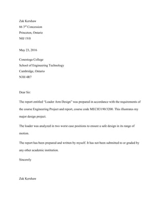
The Figure above shows link-3 and how it’s loaded. The two worst case sections have been
identified on the link. The forces on each half will be broken down into x and y components.
Then a moment will now be taken finding the internal moment at cross section A. This will be
then repeated at cross section B.
Figure 41: Section A Diagram
76. Mech 3190/3200 Report Loader Arm
Zak Kershaw 70
Figure 42: Link-3 Section A Moment Diagram
Y Forces
𝐹𝐹𝐹𝐹𝐹𝐹𝐹𝐹𝐹𝐹𝑌𝑌 = (41479)𝑠𝑠𝑠𝑠𝑠𝑠(7.02)
𝐹𝐹𝐹𝐹𝐹𝐹𝐹𝐹𝐹𝐹𝑌𝑌 = 5069.4 N
X Forces
𝐹𝐹𝐹𝐹𝐹𝐹𝐹𝐹𝐹𝐹𝑋𝑋 = (41479)𝑐𝑐𝑐𝑐𝑐𝑐(7.02)
𝐹𝐹𝐹𝐹𝐹𝐹𝐹𝐹𝐹𝐹𝑋𝑋 = 41168 𝑁𝑁 N
77. Mech 3190/3200 Report Loader Arm
Zak Kershaw 71
Table 9: Cross Section A Data Link-3
Figure 43: Cross Section A Showing Centroid
The tensile stress will now be calculated with the force over the cross-sectional area.
The bending stress will now be calculated at point A (Fig 43). The moment of inertia and
centroid distances will be taken from the SolidWorks model.
Cross Section A Data
Cross Sectional Area 1551 mm2
Moment of Inertia 295062 mm4
Partial Area A 1191 mm2
Partial Area B 360.2 mm2
A
B
Point A
Point B
Point C
FX = 41168 N
A = 1551 mm2
𝑆𝑆𝑆𝑆𝑆𝑆𝑆𝑆𝑆𝑆𝑆𝑆 𝜎𝜎 =
𝐹𝐹
𝐴𝐴
𝑆𝑆𝑆𝑆𝑆𝑆𝑆𝑆𝑆𝑆𝑆𝑆 𝜎𝜎 =
41168
(1551)
σ = 26.54 MPa Tension
M = 1071671 Nmm
I = 295062 mm4
(Cad Model)
C = 12.886 mm (Cad Model)
𝑃𝑃𝑃𝑃𝑃𝑃𝑃𝑃𝑃𝑃 𝐴𝐴 𝐵𝐵𝐵𝐵𝐵𝐵𝐵𝐵𝐵𝐵𝐵𝐵𝐵𝐵 𝑆𝑆𝑆𝑆𝑆𝑆𝑆𝑆𝑆𝑆𝑆𝑆 𝜎𝜎 =
𝑀𝑀𝑀𝑀
𝐼𝐼
𝑃𝑃𝑃𝑃𝑃𝑃𝑃𝑃𝑡𝑡 𝐴𝐴 𝐵𝐵𝐵𝐵𝐵𝐵𝐵𝐵𝐵𝐵𝐵𝐵𝐵𝐵 𝑆𝑆𝑆𝑆𝑆𝑆𝑆𝑆𝑆𝑆𝑆𝑆 𝜎𝜎 =
(1071671)(12.886)
(295062)
Point A σ = 42.12 MPa
78. Mech 3190/3200 Report Loader Arm
Zak Kershaw 72
The bending stress will now be calculated at point C.
The Transverse Shear stress at B will now be calculated.
The stresses will now be combined. Point A will be the axial stress plus the bending moment
stress since they are both placing the member into tension. Point B will be solved using Mohr’s
circle then with the principle stresses, they will be recombined into a Von Mises stress value.
Point C will be the positive axial stress plus the negative bending moment stress since the axial
V = 5069 N
Q =APY
I = 295062 mm4
(Cad Model)
A = 1191 mm2
(Cad Model)
t = 7.938 mm (Cad Model)
C = 44.264 mm (Cad Model)
Y = C/2
𝑇𝑇𝑇𝑇𝑇𝑇𝑇𝑇𝑇𝑇𝑇𝑇𝑇𝑇𝑇𝑇𝑇𝑇𝑇𝑇 𝜏𝜏 =
𝑉𝑉𝑉𝑉
𝐼𝐼𝐼𝐼
𝑇𝑇𝑇𝑇𝑇𝑇𝑇𝑇𝑇𝑇𝑇𝑇𝑇𝑇𝑇𝑇𝑇𝑇𝑇𝑇 𝜏𝜏 =
(5069)((360.2)(
44.264
2
))
(295062)(7.938)
τ = 17.25 MPa
M = 1071671 Nmm
I = 295062 mm4
(Cad Model)
C = 44.264 mm (Cad Model)
𝑃𝑃𝑃𝑃𝑃𝑃𝑃𝑃𝑃𝑃 𝐶𝐶 𝐵𝐵𝐵𝐵𝐵𝐵𝐵𝐵𝐵𝐵𝐵𝐵𝐵𝐵 𝑆𝑆𝑆𝑆𝑆𝑆𝑆𝑆𝑆𝑆𝑆𝑆 𝜎𝜎 =
𝑀𝑀𝑀𝑀
𝐼𝐼
𝑃𝑃𝑃𝑃𝑃𝑃𝑃𝑃𝑃𝑃 𝐶𝐶 𝐵𝐵𝐵𝐵𝐵𝐵𝐵𝐵𝐵𝐵𝐵𝐵𝐵𝐵 𝑆𝑆𝑆𝑆𝑆𝑆𝑆𝑆𝑠𝑠𝑠𝑠 𝜎𝜎 =
(1071671)(44.264)
(295062)
Point C σ = 160.77 MPa
79. Mech 3190/3200 Report Loader Arm
Zak Kershaw 73
stress is placing the member into tension and the bending moment is putting the member into
compression.
Point A calculated.
Point C calculated.
Point B calculated.
Axial σ = 26.54 MPa
Bending Moment = 42.12 MPa
𝑃𝑃𝑃𝑃𝑃𝑃𝑃𝑃𝑃𝑃 𝐴𝐴 𝜎𝜎 = 𝐴𝐴𝐴𝐴𝐴𝐴𝐴𝐴𝐴𝐴 𝜎𝜎 + (𝐵𝐵𝐵𝐵𝐵𝐵𝐵𝐵𝐵𝐵𝐵𝐵𝐵𝐵 𝑚𝑚𝑚𝑚𝑚𝑚𝑚𝑚𝑚𝑚𝑚𝑚)
𝑃𝑃𝑃𝑃𝑃𝑃𝑃𝑃𝑃𝑃 𝐴𝐴 𝜎𝜎 = (26.54) + (42.12)
Point A σ = 68.66 MPa Tension
Axial σ = 26.54 MPa
Bending Moment = -160.77 MPa
𝑃𝑃𝑃𝑃𝑃𝑃𝑃𝑃𝑃𝑃 𝐶𝐶 𝜎𝜎 = 𝐴𝐴𝐴𝐴𝐴𝐴𝐴𝐴𝐴𝐴 𝜎𝜎 + (+ 𝐵𝐵𝐵𝐵𝐵𝐵𝐵𝐵𝐵𝐵𝐵𝐵𝐵𝐵 𝑚𝑚𝑚𝑚𝑚𝑚𝑚𝑚𝑚𝑚𝑚𝑚)
𝑃𝑃𝑃𝑃𝑃𝑃𝑃𝑃𝑃𝑃 𝐶𝐶 𝜎𝜎 = (26.54) + (−160.77)
Point C σ = 134.2 MPa Compression
80. Mech 3190/3200 Report Loader Arm
Zak Kershaw 74
Figure 44: Point B Link-3 Mohr's Circle Cross Section A
Using sigma one and two a Von Mises stress will be calculated.
81. Mech 3190/3200 Report Loader Arm
Zak Kershaw 75
The material is ductile iron grade 80-60-03 with a yield strength of 379 MPa and an ultimate
strength of 552 MPa. Only the lowest safety factor will be calculated but a table will list the rest
of the safety factors.
𝑃𝑃𝑃𝑃𝑃𝑃𝑃𝑃𝑃𝑃 𝐶𝐶 𝑁𝑁 =
𝑆𝑆𝑌𝑌
𝜎𝜎
𝑃𝑃𝑃𝑃𝑃𝑃𝑃𝑃𝑃𝑃 𝐶𝐶 𝑁𝑁 =
379
157.5
𝑷𝑷𝑷𝑷𝑷𝑷𝑷𝑷𝑷𝑷 𝑪𝑪 𝑺𝑺𝑺𝑺𝑺𝑺𝑺𝑺𝑺𝑺𝑺𝑺 𝑭𝑭𝑭𝑭𝑭𝑭𝑭𝑭𝑭𝑭𝑭𝑭 𝑵𝑵 = 𝟑𝟑. 𝟓𝟓𝟓𝟓
Table 10: Cross Section A Stress Summary
Type of Stress Stress Value Safety Factor
Cross Section A Point A Stress 68.66 5.52
Cross Section A Point B Stress 39.96 9.48
Cross Section A Point C Stress 134.2 2.41
The following stress calculations for section A will now be repeated for section B.
σ P1 = 26.61 MPa
σ P2 = -0.072 MPa
𝜎𝜎′ = �𝜎𝜎𝑃𝑃1
2
+ 𝜎𝜎𝑃𝑃2
2
− 𝜎𝜎𝑃𝑃1 𝜎𝜎𝑃𝑃2
𝜎𝜎′ = �35.032 + (−8.49)2 − 35.03(−8.49)
σ' = 39.96 MPa
82. Mech 3190/3200 Report Loader Arm
Zak Kershaw 76
Figure 45: Section B Diagram
Y Forces
𝐹𝐹𝐹𝐹𝐹𝐹𝐹𝐹𝐹𝐹𝑌𝑌 = (41479)𝑠𝑠𝑠𝑠𝑠𝑠(12.98)
𝐹𝐹𝐹𝐹𝐹𝐹𝐹𝐹𝐹𝐹𝑌𝑌 =9317 N
X Forces
𝐹𝐹𝐹𝐹𝐹𝐹𝐹𝐹𝐹𝐹𝑋𝑋 = (41479)𝑐𝑐𝑐𝑐𝑐𝑐(12.98)
𝐹𝐹𝐹𝐹𝐹𝐹𝐹𝐹𝐹𝐹𝑋𝑋 = 40419 𝑁𝑁 N
83. Mech 3190/3200 Report Loader Arm
Zak Kershaw 77
Figure 46: Link-3 Section B Moment Diagram
84. Mech 3190/3200 Report Loader Arm
Zak Kershaw 78
Table 11: Cross Section B Data Link-3
Figure 47: Cross Section B
The tensile stress will now be calculated with the force over the cross-sectional area.
The bending stress will now be calculated at point A. From the bending moment multiplied by
the top distance to the centroid over the moment of inertia. The moment of inertia and centroid
distances will be taken from the SolidWorks model.
Cross Section B Data
Cross Sectional Area Both
Sides
1972 mm2
Moment of Inertia Both
Sides
515913 mm4
FX = 40419 N
A = 1972 mm2
𝑆𝑆𝑆𝑆𝑆𝑆𝑆𝑆𝑆𝑆𝑆𝑆 𝜎𝜎 =
𝐹𝐹
𝐴𝐴
𝑆𝑆𝑆𝑆𝑆𝑆𝑆𝑆𝑆𝑆𝑆𝑆 𝜎𝜎 =
40419
1972
σ = 20.50 MPa Tension
M = 320598 Nmm
I = 515913 mm4
(Cad Model)
H = 57.15 mm (Cad Model)
C = H/2
𝑃𝑃𝑃𝑃𝑃𝑃𝑃𝑃𝑃𝑃 𝐴𝐴 𝐵𝐵𝐵𝐵𝐵𝐵𝐵𝐵𝐵𝐵𝐵𝐵𝐵𝐵 𝑆𝑆𝑆𝑆𝑆𝑆𝑆𝑆𝑆𝑆𝑆𝑆 𝜎𝜎 =
𝑀𝑀𝑀𝑀
𝐼𝐼
𝑃𝑃𝑃𝑃𝑃𝑃𝑃𝑃𝑃𝑃 𝐴𝐴 𝐵𝐵𝐵𝐵𝐵𝐵𝐵𝐵𝐵𝐵𝐵𝐵𝐵𝐵 𝑆𝑆𝑆𝑆𝑆𝑆𝑒𝑒𝑠𝑠𝑠𝑠 𝜎𝜎 =
(320598)(
57.15
2
)
(519913)
Point A σ = 17.62 MPa
Point A
Point B
Point C
85. Mech 3190/3200 Report Loader Arm
Zak Kershaw 79
The bending stress at point C will not be calculated because the cross section does not change
and the value for point A and C is the same. Point C is in compression while point A is in
tension.
The Transverse Shear stress will now be calculated.
The stresses will now be combined. Point A will be the axial stress plus the bending moment
stress since they are both placing the member into tension. Point B will be solved using Mohr’s
circle then with the principle stresses, they will be recombined into a Von Mises stress value.
Point C will be the positive axial stress plus the negative bending moment stress since the axial
stress is placing the member into tension and the bending moment is putting the member into
compression.
V = 9317 N
Q =APY
AP = A/2
Y = C/4
I = 515913 mm4
(Cad Model)
A = 1972 mm2
(Cad Model)
t = 17.63 x 2 mm (Cad Model)
C = 57.15 mm (Cad Model)
𝑇𝑇𝑇𝑇𝑇𝑇𝑇𝑇𝑇𝑇𝑇𝑇𝑇𝑇𝑇𝑇𝑇𝑇𝑇𝑇 𝜏𝜏 =
(𝑉𝑉)(𝑄𝑄)
(𝐼𝐼)(𝑡𝑡)
𝑇𝑇𝑟𝑟𝑟𝑟𝑟𝑟𝑟𝑟𝑟𝑟𝑟𝑟𝑟𝑟𝑟𝑟𝑟𝑟 𝜏𝜏 =
(9317)((
1972
2
)(
57.15
4
))
(515913)(17.63 𝑥𝑥 2)
τ = 7.16 MPa
86. Mech 3190/3200 Report Loader Arm
Zak Kershaw 80
Point A calculated.
Point C calculated.
Point B calculated.
Axial σ = 20.50 MPa
Bending Moment = 17.62 MPa
𝑃𝑃𝑃𝑃𝑃𝑃𝑃𝑃𝑃𝑃 𝐴𝐴 𝜎𝜎 = 𝐴𝐴𝐴𝐴𝐴𝐴𝐴𝐴𝐴𝐴 𝜎𝜎 + (𝐵𝐵𝐵𝐵𝐵𝐵𝐵𝐵𝐵𝐵𝐵𝐵𝐵𝐵 𝑚𝑚𝑚𝑚𝑚𝑚𝑚𝑚𝑚𝑚𝑚𝑚)
𝑃𝑃𝑃𝑃𝑃𝑃𝑃𝑃𝑃𝑃 𝐴𝐴 𝜎𝜎 = (20.5) + (17.62)
Point A σ = 38.12 MPa Tension
Axial σ = 20.50 MPa
Bending Moment = -17.62 MPa
𝑃𝑃𝑃𝑃𝑃𝑃𝑃𝑃𝑃𝑃 𝐶𝐶 𝜎𝜎 = 𝐴𝐴𝐴𝐴𝐴𝐴𝐴𝐴𝐴𝐴 𝜎𝜎 + (+ 𝐵𝐵𝐵𝐵𝐵𝐵𝐵𝐵𝐵𝐵𝐵𝐵𝐵𝐵 𝑚𝑚𝑚𝑚𝑚𝑚𝑚𝑚𝑚𝑚𝑚𝑚)
𝑃𝑃𝑃𝑃𝑃𝑃𝑃𝑃𝑃𝑃 𝐶𝐶 𝜎𝜎 = (20.5) + (−17.62)
Point C σ = 2.88 MPa Compression
87. Mech 3190/3200 Report Loader Arm
Zak Kershaw 81
Figure 48: Point B Link-3 Mohr's Circle Cross Section B
Using sigma one and two a Von Mises stress will be calculated.
88. Mech 3190/3200 Report Loader Arm
Zak Kershaw 82
The material is ductile iron grade 80-55-06 with a yield strength of 379 MPa and an ultimate
strength of 552 MPa. Only the lowest safety factor will be calculated but a table will list the rest
of the safety factors.
𝑃𝑃𝑃𝑃𝑃𝑃𝑃𝑃𝑃𝑃 𝐴𝐴 𝑁𝑁 =
𝑆𝑆𝑌𝑌
𝜎𝜎
𝑃𝑃𝑃𝑃𝑃𝑃𝑃𝑃𝑃𝑃 𝐴𝐴 𝑁𝑁 =
379
38.12
𝑷𝑷𝑷𝑷𝑷𝑷𝑷𝑷𝑷𝑷 𝑨𝑨 𝑺𝑺𝑺𝑺𝑺𝑺𝑺𝑺𝑺𝑺𝑺𝑺 𝑭𝑭𝑭𝑭𝑭𝑭𝑭𝑭𝑭𝑭𝑭𝑭 𝑵𝑵 = 𝟗𝟗. 𝟗𝟗𝟗𝟗
Table 12: Cross Section B Stress Summary
Type of Stress Stress Value Safety Factor
Cross Section B Point A Stress 38.12 9.94
Cross Section B Point B Stress 23.96 15.82
Cross Section B Point C Stress 2.88 131.6
The shear tear out stress will now be calculated with the force over the area in shear. For both
ends of the link.
σ P1 = 22.753 MPa
σ P2 = -2.253 MPa
𝜎𝜎′ = �𝜎𝜎𝑃𝑃1
2
+ 𝜎𝜎𝑃𝑃2
2
− 𝜎𝜎𝑃𝑃1 𝜎𝜎𝑃𝑃2
𝜎𝜎′ = �22.7532 + (−2.253)2 − 22.753(−2.253)
σ' = 23.96 MPa
89. Mech 3190/3200 Report Loader Arm
Zak Kershaw 83
Figure 49: Shear Stress Tearout Link-3
F = 41479 N
As = 1399 mm2
𝑆𝑆ℎ𝑒𝑒𝑒𝑒𝑒𝑒 𝑇𝑇𝑇𝑇𝑇𝑇𝑇𝑇𝑇𝑇𝑇𝑇𝑇𝑇 𝜏𝜏 =
𝐹𝐹
𝐴𝐴𝑠𝑠
𝑆𝑆ℎ𝑒𝑒𝑒𝑒𝑒𝑒 𝑇𝑇𝑇𝑇𝑇𝑇𝑇𝑇𝑇𝑇𝑇𝑇𝑇𝑇 𝜏𝜏 =
41479
1399
τ = 29.65 MPa
F = 41479 N
As = 4275 mm2
𝑆𝑆ℎ𝑒𝑒𝑒𝑒𝑒𝑒 𝑇𝑇𝑇𝑇𝑇𝑇𝑇𝑇𝑇𝑇𝑇𝑇𝑇𝑇 𝜏𝜏 =
𝐹𝐹
𝐴𝐴𝑠𝑠
𝑆𝑆ℎ𝑒𝑒𝑒𝑒𝑒𝑒 𝑇𝑇𝑇𝑇𝑇𝑇𝑇𝑇𝑇𝑇𝑇𝑇𝑇𝑇 𝜏𝜏 =
41479
4275
τ = 9.70 MPa
90. Mech 3190/3200 Report Loader Arm
Zak Kershaw 84
The material is ductile iron grade 80-55-06 with a yield strength of 379 MPa and an ultimate
strength of 552 MPa. Only the lowest safety factor will be calculated but a table will list the rest
of the safety factors. The SUS value for this ductile iron is 503 MPa and the safety factor will only
be calculated for the highest stress value.
𝑆𝑆𝑆𝑆𝑆𝑆𝑆𝑆𝑆𝑆𝑆𝑆 𝐹𝐹𝐹𝐹𝐹𝐹𝐹𝐹𝐹𝐹𝐹𝐹 𝑆𝑆ℎ𝑒𝑒𝑒𝑒𝑒𝑒 𝑇𝑇𝑇𝑇𝑇𝑇𝑇𝑇𝑇𝑇𝑇𝑇𝑇𝑇 =
𝑆𝑆𝑈𝑈𝑈𝑈
𝜏𝜏𝑆𝑆ℎ𝑒𝑒𝑒𝑒𝑒𝑒 𝑇𝑇𝑇𝑇𝑇𝑇𝑇𝑇𝑇𝑇𝑇𝑇𝑇𝑇
𝑆𝑆𝑆𝑆𝑆𝑆𝑆𝑆𝑆𝑆𝑆𝑆 𝐹𝐹𝐹𝐹𝐹𝐹𝐹𝐹𝐹𝐹𝐹𝐹 𝑆𝑆ℎ𝑒𝑒𝑒𝑒𝑒𝑒 𝑇𝑇𝑇𝑇𝑇𝑇𝑇𝑇𝑇𝑇𝑇𝑇𝑇𝑇 =
503
29.65
𝑺𝑺𝑺𝑺𝑺𝑺𝑺𝑺𝑺𝑺𝑺𝑺 𝑭𝑭𝑭𝑭𝑭𝑭𝑭𝑭𝑭𝑭𝑭𝑭 𝑺𝑺𝑺𝑺𝑺𝑺𝑺𝑺𝑺𝑺 𝑻𝑻𝑻𝑻𝑻𝑻𝑻𝑻𝑻𝑻𝑻𝑻𝑻𝑻 = 𝟏𝟏𝟏𝟏. 𝟗𝟗𝟗𝟗 > 𝟐𝟐
Since the safety factor is greater than 2 Link-3 will not fail due to shear stress with the proposed
material.
Figure 50: Tensile Stress Tearout Link-3
91. Mech 3190/3200 Report Loader Arm
Zak Kershaw 85
The tensile tear out stress will now be calculated with the force over the area in shear. For both
ends of the link.
The material is ductile iron grade 80-55-06 with a yield strength of 379 MPa and an ultimate
strength of 552 MPa. Only the lowest safety factor will be calculated but a table will list the rest
of the safety factors
𝑇𝑇𝑇𝑇𝑇𝑇𝑇𝑇𝑇𝑇𝑇𝑇𝑇𝑇 𝑆𝑆𝑆𝑆𝑆𝑆𝑆𝑆𝑆𝑆𝑆𝑆 𝑁𝑁 =
𝑆𝑆𝑌𝑌
𝜎𝜎
𝑇𝑇𝑇𝑇𝑇𝑇𝑇𝑇𝑇𝑇𝑇𝑇𝑇𝑇 𝑆𝑆𝑆𝑆𝑆𝑆𝑆𝑆𝑆𝑆𝑆𝑆 𝑁𝑁 =
379
55.48
𝑺𝑺𝑺𝑺𝑺𝑺𝑺𝑺𝑺𝑺𝑺𝑺 𝑭𝑭𝑭𝑭𝑭𝑭𝑭𝑭𝑭𝑭𝑭𝑭 𝑵𝑵 = 𝟔𝟔. 𝟖𝟖𝟖𝟖
F = 41479 N
A = 747.7 mm2
𝑆𝑆𝑆𝑆𝑆𝑆𝑆𝑆𝑆𝑆𝑆𝑆 𝐹𝐹𝐹𝐹𝐹𝐹𝐹𝐹𝐹𝐹𝐹𝐹 𝑆𝑆𝑆𝑆𝑆𝑆𝑆𝑆𝑆𝑆𝑆𝑆 𝜎𝜎 =
𝐹𝐹
𝐴𝐴
𝑆𝑆𝑆𝑆𝑆𝑆𝑆𝑆𝑆𝑆𝑆𝑆 𝐹𝐹𝐹𝐹𝐹𝐹𝐹𝐹𝐹𝐹𝐹𝐹 𝑆𝑆𝑆𝑆𝑆𝑆𝑆𝑆𝑆𝑆𝑆𝑆 𝜎𝜎 =
41479
747.7
𝝈𝝈 = 55.48 MPa
F = 41479 N
A = 2109 mm2
𝑆𝑆𝑆𝑆𝑆𝑆𝑆𝑆𝑆𝑆𝑆𝑆 𝐹𝐹𝐹𝐹𝐹𝐹𝐹𝐹𝐹𝐹𝐹𝐹 𝑆𝑆𝑆𝑆𝑆𝑆𝑆𝑆𝑆𝑆𝑆𝑆 𝑁𝑁 =
𝐹𝐹
𝐴𝐴
𝑆𝑆𝑆𝑆𝑆𝑆𝑆𝑆𝑆𝑆𝑆𝑆 𝐹𝐹𝐹𝐹𝐹𝐹𝐹𝐹𝐹𝐹𝐹𝐹 𝑆𝑆𝑆𝑆𝑆𝑆𝑆𝑆𝑆𝑆𝑆𝑆 𝑁𝑁 =
41479
2109
N = 19.67 MPa
92. Mech 3190/3200 Report Loader Arm
Zak Kershaw 86
2.6.1 Link-3 Summary
Link-3 did not have any safety factors under 2 so this will part will not fail under combined
loading, tensile tearout stress or shear tearout stress. The next table list the results.
Table 13: Link-3 Safety Factor Table Breakout Position
Type of Stress Stress Value Safety Factor
Combined Loading Point A Cross Section A 68.66 5.52
Combined Loading Point B Cross Section A 39.96 9.48
Combined Loading Point C Cross Section A 134.2 2.41
Combined Loading Point A Cross Section B 38.12 9.94
Combined Loading Point B Cross Section B 23.96 15.82
Combined Loading Point C Cross Section B 2.88 131.6
Shear Tearout Left Side 9.70 51.86
Shear Tearout Right Side 29.65 16.96
Tensile Tearout Left Side 19.67 19.27
Tensile Tearout Right Side 55.48 6.83
2.7 Stress Calculations Bellcrank
The bellcrank is made from ductile iron grade 80-55-06 with a yield strength of 379 MPa and an
ultimate strength of 552 MPa. The materials properties can also be found in the appendices under
Appendices B figure “Link-3 & Bellcrank from Matt Web”. The stress calculations for the
Bellcrank were done these include doing to cross-sectional analyses of the bellcrank in two cross
sections and doing all of the tensile tearouts and shear tearouts. The bellcrank was done in both
93. Mech 3190/3200 Report Loader Arm
Zak Kershaw 87
positions because the values are very close to each other meaning a clear worst-case position
could not be identified.
2.7.1 Bellcrank Stress Calculations Breakout Position
Figure 51: Bellcrank Loading Diagram
94. Mech 3190/3200 Report Loader Arm
Zak Kershaw 88
Figure 52: Bellcrank loaded with Cross Sections Shown
The Figure above shows the bellcrank in the breakout position and how it’s loaded. The two
worst case sections have been identified on the bellcrank. The forces on each half will be broken
down into x and y components. Then a moment will now be taken finding the internal moment at
cross section A. This will be then repeated at cross section B.
Figure 53: Section A Bellcrank
95. Mech 3190/3200 Report Loader Arm
Zak Kershaw 89
Figure 54: Bellcrank Section A Moment Diagram
Y Forces
𝐹𝐹𝐹𝐹𝐹𝐹𝐹𝐹𝐹𝐹𝑌𝑌 = (47209)𝑠𝑠𝑠𝑠𝑠𝑠(46.78)
𝐹𝐹𝐹𝐹𝐹𝐹𝐹𝐹𝐹𝐹𝑌𝑌 = 34403 N
X Forces
𝐹𝐹𝐹𝐹𝐹𝐹𝐹𝐹𝐹𝐹𝑋𝑋 = (47209)𝑐𝑐𝑐𝑐𝑐𝑐(46.78)
𝐹𝐹𝐹𝐹𝐹𝐹𝐹𝐹𝐹𝐹𝑋𝑋 = 32329 N
96. Mech 3190/3200 Report Loader Arm
Zak Kershaw 90
Table 14: Cross-Sectional Data Section A Bellcrank
Figure 55: Cross Section A Showing Centroid
The tensile stress will now be calculated with the force over the cross-sectional area.
The bending stress will now be calculated at point A (Fig 43). The moment of inertia and
centroid distances will be taken from the SolidWorks model.
Cross Section A Data
Cross Sectional Area 6290 mm2
Moment of Inertia 2315863 mm4
Point A
Point B
Point C
FX = 34403 N
A = 6290 mm2
𝑆𝑆𝑆𝑆𝑆𝑆𝑆𝑆𝑆𝑆𝑆𝑆 𝜎𝜎 =
𝐹𝐹
𝐴𝐴
𝑆𝑆𝑆𝑆𝑆𝑆𝑆𝑆𝑆𝑆𝑆𝑆 𝜎𝜎 =
34403
(6290)
σ = 5.47 MPa Compression
M = 1370749 Nmm
I = 2315863 mm4
(Cad Model)
h = 94.7 mm (Cad Model)
C = h/2
𝑃𝑃𝑃𝑃𝑃𝑃𝑃𝑃𝑡𝑡 𝐴𝐴 𝐵𝐵𝐵𝐵𝐵𝐵𝐵𝐵𝐵𝐵𝐵𝐵𝐵𝐵 𝑆𝑆𝑆𝑆𝑆𝑆𝑆𝑆𝑆𝑆𝑆𝑆 𝜎𝜎 =
𝑀𝑀𝑀𝑀
𝐼𝐼
𝑃𝑃𝑃𝑃𝑃𝑃𝑃𝑃𝑃𝑃 𝐴𝐴 𝐵𝐵𝐵𝐵𝐵𝐵𝐵𝐵𝐵𝐵𝐵𝐵𝐵𝐵 𝑆𝑆𝑆𝑆𝑆𝑆𝑆𝑆𝑆𝑆𝑆𝑆 𝜎𝜎 =
(1370749)(
94.7
2
)
(2315863)
Point A σ = 28.03 MPa Tension
97. Mech 3190/3200 Report Loader Arm
Zak Kershaw 91
The bending stress will now be calculated at point C.
The Transverse Shear stress at B will now be calculated.
V = 32329 N
Q =APY
I = 2315863 mm4
(Cad Model)
A = 6290 mm2
(Cad Model)
t = 66.7 mm (Cad Model)
C = 94.7 mm (Cad Model)
Y = C/4
𝑇𝑇𝑇𝑇𝑇𝑇𝑇𝑇𝑇𝑇𝑇𝑇𝑇𝑇𝑇𝑇𝑇𝑇𝑇𝑇 𝜏𝜏 =
𝑉𝑉𝑉𝑉
𝐼𝐼𝐼𝐼
𝑇𝑇𝑇𝑇𝑇𝑇𝑇𝑇𝑇𝑇𝑇𝑇𝑇𝑇𝑇𝑇𝑇𝑇𝑇𝑇 𝜏𝜏 =
(32329)((
6290
2
)(
94.7
4
))
(2315863)(66.7)
τ = 15.58 MPa
M = 1370749 Nmm
I = 2315863 mm4
(Cad Model)
h = 94.7 mm (Cad Model)
C = h/2
𝑃𝑃𝑃𝑃𝑃𝑃𝑃𝑃𝑃𝑃 𝐶𝐶 𝐵𝐵𝐵𝐵𝑛𝑛𝑑𝑑𝑑𝑑𝑑𝑑𝑑𝑑 𝑆𝑆𝑆𝑆𝑆𝑆𝑆𝑆𝑆𝑆𝑆𝑆 𝜎𝜎 =
𝑀𝑀𝑀𝑀
𝐼𝐼
𝑃𝑃𝑃𝑃𝑃𝑃𝑃𝑃𝑃𝑃 𝐶𝐶 𝐵𝐵𝐵𝐵𝐵𝐵𝐵𝐵𝐵𝐵𝐵𝐵𝐵𝐵 𝑆𝑆𝑆𝑆𝑆𝑆𝑆𝑆𝑆𝑆𝑆𝑆 𝜎𝜎 =
(1370749)(
94.7
2
)
(2315863)
Point C σ = 28.03 MPa Compression
98. Mech 3190/3200 Report Loader Arm
Zak Kershaw 92
The stresses will now be combined.
Point A calculated.
Point C calculated.
Point B calculated.
Axial σ = -5.47 MPa
Bending Moment = 28.03 MPa
𝑃𝑃𝑃𝑃𝑃𝑃𝑃𝑃𝑃𝑃 𝐴𝐴 𝜎𝜎 = 𝐴𝐴𝐴𝐴𝐴𝐴𝐴𝐴𝐴𝐴 𝜎𝜎 + (𝐵𝐵𝐵𝐵𝐵𝐵𝐵𝐵𝐵𝐵𝐵𝐵𝐵𝐵 𝑚𝑚𝑚𝑚𝑚𝑚𝑒𝑒𝑛𝑛𝑛𝑛)
𝑃𝑃𝑃𝑃𝑃𝑃𝑃𝑃𝑃𝑃 𝐴𝐴 𝜎𝜎 = (−5.47) + (28.03)
Point A σ = 22.56 MPa Tension
Axial σ = -5.47 MPa
Bending Moment = -28.03 MPa
𝑃𝑃𝑃𝑃𝑃𝑃𝑃𝑃𝑃𝑃 𝐶𝐶 𝜎𝜎 = 𝐴𝐴𝐴𝐴𝐴𝐴𝐴𝐴𝐴𝐴 𝜎𝜎 + (+ 𝐵𝐵𝐵𝐵𝐵𝐵𝐵𝐵𝐵𝐵𝐵𝐵𝐵𝐵 𝑚𝑚𝑚𝑚𝑚𝑚𝑚𝑚𝑚𝑚𝑚𝑚)
𝑃𝑃𝑃𝑃𝑃𝑃𝑃𝑃𝑃𝑃 𝐶𝐶 𝜎𝜎 = (−5.47) + (−28.03)
Point C σ = 33.5 MPa Compression
99. Mech 3190/3200 Report Loader Arm
Zak Kershaw 93
Figure 56: Point B Bellcrank Mohr's Circle Cross Section A
Using sigma one and two a Von Mises stress will be calculated.
100. Mech 3190/3200 Report Loader Arm
Zak Kershaw 94
The material is ductile iron grade 80-60-03 with a yield strength of 379 MPa and an ultimate
strength of 552 MPa. Only the lowest safety factor will be calculated but a table will list the rest
of the safety factors.
𝑃𝑃𝑃𝑃𝑃𝑃𝑃𝑃𝑃𝑃 𝐶𝐶 𝑁𝑁 =
𝑆𝑆𝑌𝑌
𝜎𝜎
𝑃𝑃𝑃𝑃𝑃𝑃𝑃𝑃𝑃𝑃 𝐶𝐶 𝑁𝑁 =
379
33.5
𝑷𝑷𝑷𝑷𝑷𝑷𝑷𝑷𝑷𝑷 𝑪𝑪 𝑺𝑺𝑺𝑺𝑺𝑺𝑺𝑺𝑺𝑺𝑺𝑺 𝑭𝑭𝑭𝑭𝑭𝑭𝑭𝑭𝑭𝑭𝑭𝑭 𝑵𝑵 = 𝟏𝟏𝟏𝟏. 𝟑𝟑𝟑𝟑
Table 15: Cross Section A Stress Summary
Type of Stress Stress Value Safety Factor
Cross Section A Point A Stress 22.56 16.8
Cross Section A Point B Stress 27.52 13.77
Cross Section A Point C Stress 33.5 11.31
The following stress calculations for section A will now be repeated for section B.
σ P1 = 13.083 MPa
σ P2 = -18.553 MPa
𝜎𝜎′ = �𝜎𝜎𝑃𝑃1
2
+ 𝜎𝜎𝑃𝑃2
2
− 𝜎𝜎𝑃𝑃1 𝜎𝜎𝑃𝑃2
𝜎𝜎′ = �13.0832 + (−18.533)2 − 13.083(−18.553)
σ' = 27.52 MPa
101. Mech 3190/3200 Report Loader Arm
Zak Kershaw 95
Figure 57: Section B Bellcrank
Y Forces
𝐹𝐹𝐹𝐹𝐹𝐹𝐹𝐹𝐹𝐹𝑌𝑌 = (42343)𝑐𝑐𝑐𝑐𝑐𝑐(12.42)
𝐹𝐹𝐹𝐹𝐹𝐹𝐹𝐹𝐹𝐹𝑌𝑌 =41352 N
X Forces
𝐹𝐹𝐹𝐹𝐹𝐹𝐹𝐹𝐹𝐹𝑋𝑋 = (42343)𝑠𝑠𝑠𝑠𝑠𝑠(12.42)
𝐹𝐹𝐹𝐹𝐹𝐹𝐹𝐹𝐹𝐹𝑋𝑋 = 9107 N
102. Mech 3190/3200 Report Loader Arm
Zak Kershaw 96
Figure 58: Bellcrank Section B Moment Diagram
103. Mech 3190/3200 Report Loader Arm
Zak Kershaw 97
Table 16: Cross-Sectional Data Section A Bellcrank
Figure 59: Cross Section B Showing Centroid
The tensile stress will now be calculated with the force over the cross-sectional area.
Cross Section B Data
Cross Sectional Area 4251 mm2
Moment of Inertia 4411218 mm4
Point A
Point B
Point C
FX = 9107 N
A = 4251 mm2
𝑆𝑆𝑆𝑆𝑆𝑆𝑆𝑆𝑆𝑆𝑆𝑆 𝜎𝜎 =
𝐹𝐹
𝐴𝐴
𝑆𝑆𝑆𝑆𝑆𝑆𝑆𝑆𝑆𝑆𝑆𝑆 𝜎𝜎 =
9107
(4251)
σ = 2.14 MPa Compression
104. Mech 3190/3200 Report Loader Arm
Zak Kershaw 98
The bending stress will now be calculated at point A (Fig 43). The moment of inertia and
centroid distances will be taken from the SolidWorks model.
The bending stress will now be calculated at point C.
The Transverse Shear stress at B will now be calculated.
M = 1248830 Nmm
I = 4411218 mm4
(Cad Model)
h = 112.1 mm (Cad Model)
C = h/2
𝑃𝑃𝑃𝑃𝑃𝑃𝑃𝑃𝑃𝑃 𝐴𝐴 𝐵𝐵𝐵𝐵𝐵𝐵𝐵𝐵𝐵𝐵𝐵𝐵𝐵𝐵 𝑆𝑆𝑆𝑆𝑆𝑆𝑆𝑆𝑆𝑆𝑆𝑆 𝜎𝜎 =
𝑀𝑀𝑀𝑀
𝐼𝐼
𝑃𝑃𝑃𝑃𝑃𝑃𝑃𝑃𝑃𝑃 𝐶𝐶 𝐵𝐵𝐵𝐵𝐵𝐵𝐵𝐵𝐵𝐵𝐵𝐵𝐵𝐵 𝑆𝑆𝑆𝑆𝑆𝑆𝑆𝑆𝑆𝑆𝑆𝑆 𝜎𝜎 =
(1248830)(
112.1
2
)
(4411218)
Point A σ = 15.87 MPa Compression
M = 1248830 Nmm
I = 4411218 mm4
(Cad Model)
h = 112.1 mm (Cad Model)
C = h/2
𝑃𝑃𝑃𝑃𝑃𝑃𝑃𝑃𝑃𝑃 𝐶𝐶 𝐵𝐵𝐵𝐵𝐵𝐵𝐵𝐵𝐵𝐵𝐵𝐵𝐵𝐵 𝑆𝑆𝑆𝑆𝑆𝑆𝑆𝑆𝑆𝑆𝑆𝑆 𝜎𝜎 =
𝑀𝑀𝑀𝑀
𝐼𝐼
𝑃𝑃𝑃𝑃𝑃𝑃𝑃𝑃𝑃𝑃 𝐶𝐶 𝐵𝐵𝐵𝐵𝐵𝐵𝐵𝐵𝐵𝐵𝐵𝐵𝐵𝐵 𝑆𝑆𝑆𝑆𝑆𝑆𝑆𝑆𝑆𝑆𝑆𝑆 𝜎𝜎 =
(1248830)(
112.1
2
)
(4411218)
Point C σ = 15.87 MPa Tension
105. Mech 3190/3200 Report Loader Arm
Zak Kershaw 99
The stresses will now be combined.
Point A calculated.
Point C calculated.
V = 41352 N
Q =APY
I = 4411218 mm4
(Cad Model)
A = 4251 mm2
(Cad Model)
t = 38.2 mm (Cad Model)
C = 112.1 mm (Cad Model)
Y = C/4
𝑇𝑇𝑇𝑇𝑇𝑇𝑇𝑇𝑇𝑇𝑇𝑇𝑇𝑇𝑇𝑇𝑇𝑇𝑇𝑇 𝜏𝜏 =
𝑉𝑉𝑉𝑉
𝐼𝐼𝐼𝐼
𝑇𝑇𝑇𝑇𝑇𝑇𝑇𝑇𝑇𝑇𝑇𝑇𝑇𝑇𝑇𝑇𝑇𝑇𝑇𝑇 𝜏𝜏 =
(41352)((
4251
2
)(
112.1
4
))
(4411218)(38.2)
τ = 14.62 MPa
Axial σ = -2.14 MPa
Bending Moment = 18.01 MPa
𝑃𝑃𝑃𝑃𝑃𝑃𝑃𝑃𝑃𝑃 𝐴𝐴 𝜎𝜎 = 𝐴𝐴𝐴𝐴𝐴𝐴𝐴𝐴𝐴𝐴 𝜎𝜎 + (𝐵𝐵𝑒𝑒𝑛𝑛𝑛𝑛𝑛𝑛𝑛𝑛𝑛𝑛 𝑚𝑚𝑚𝑚𝑚𝑚𝑚𝑚𝑚𝑚𝑚𝑚)
𝑃𝑃𝑃𝑃𝑃𝑃𝑃𝑃𝑃𝑃 𝐴𝐴 𝜎𝜎 = (−2.14) + (18.01)
Point A σ = 13.73 MPa Tension
Axial σ = -2.14 MPa
Bending Moment = -18.01 MPa
𝑃𝑃𝑃𝑃𝑃𝑃𝑃𝑃𝑃𝑃 𝐶𝐶 𝜎𝜎 = 𝐴𝐴𝐴𝐴𝐴𝐴𝐴𝐴𝐴𝐴 𝜎𝜎 + (+ 𝐵𝐵𝐵𝐵𝐵𝐵𝐵𝐵𝐵𝐵𝐵𝐵𝐵𝐵 𝑚𝑚𝑚𝑚𝑚𝑚𝑚𝑚𝑚𝑚𝑚𝑚)
𝑃𝑃𝑃𝑃𝑃𝑃𝑃𝑃𝑃𝑃 𝐶𝐶 𝜎𝜎 = (−2.14) + (−18.01)
Point C σ = 18.01 MPa Compression
106. Mech 3190/3200 Report Loader Arm
Zak Kershaw 100
Point B calculated.
Figure 60: Point B Bellcrank Mohr's Circle Cross Section B
Using sigma one and two a Von Mises stress will be calculated.
107. Mech 3190/3200 Report Loader Arm
Zak Kershaw 101
The material is ductile iron grade 80-60-03 with a yield strength of 379 MPa and an ultimate
strength of 552 MPa. Only the lowest safety factor will be calculated but a table will list the rest
of the safety factors.
𝑃𝑃𝑃𝑃𝑃𝑃𝑃𝑃𝑃𝑃 𝐶𝐶 𝑁𝑁 =
𝑆𝑆𝑌𝑌
𝜎𝜎
𝑃𝑃𝑃𝑃𝑃𝑃𝑃𝑃𝑃𝑃 𝐶𝐶 𝑁𝑁 =
379
25.41
𝑷𝑷𝑷𝑷𝑷𝑷𝑷𝑷𝑷𝑷 𝑪𝑪 𝑺𝑺𝑺𝑺𝑺𝑺𝑺𝑺𝑺𝑺𝑺𝑺 𝑭𝑭𝑭𝑭𝑭𝑭𝑭𝑭𝑭𝑭𝑭𝑭 𝑵𝑵 = 𝟏𝟏𝟏𝟏. 𝟗𝟗𝟗𝟗
Table 17: Cross Section B Stress Summary
Type of Stress Stress Value Safety Factor
Cross Section B Point A Stress 13.73 27.60
Cross Section B Point B Stress 25.41 14.92
Cross Section B Point C Stress 18.01 21.04
The shear tear out stress will now be calculated with the force over the area in shear.
σ P1 = 13.589 MPa
σ P2 = -15.729 MPa
𝜎𝜎′ = �𝜎𝜎𝑃𝑃1
2
+ 𝜎𝜎𝑃𝑃2
2
− 𝜎𝜎𝑃𝑃1 𝜎𝜎𝑃𝑃2
𝜎𝜎′ = �13.5892 + (−15.729)2 − 13.589(−15.729)
σ' = 25.41 MPa
108. Mech 3190/3200 Report Loader Arm
Zak Kershaw 102
Figure 61: Shear Stress Tearout Bellcrank Breakout Position
F = 49248 N
As = 4907 mm2
𝑆𝑆ℎ𝑒𝑒𝑒𝑒𝑒𝑒 𝑇𝑇𝑇𝑇𝑇𝑇𝑇𝑇𝑇𝑇𝑇𝑇𝑇𝑇 𝐴𝐴 𝜏𝜏 =
𝐹𝐹
𝐴𝐴𝑠𝑠
𝑆𝑆ℎ𝑒𝑒𝑒𝑒𝑒𝑒 𝑇𝑇𝑇𝑇𝑇𝑇𝑇𝑇𝑇𝑇𝑇𝑇𝑇𝑇 𝐴𝐴 𝜏𝜏 =
49248
4907
A τ = 10.04 MPa
F = 42343 N
As = 4599 mm2
𝑆𝑆ℎ𝑒𝑒𝑒𝑒𝑒𝑒 𝑇𝑇𝑇𝑇𝑇𝑇𝑇𝑇𝑇𝑇𝑇𝑇𝑇𝑇 𝐵𝐵 𝜏𝜏 =
𝐹𝐹
𝐴𝐴𝑠𝑠
𝑆𝑆ℎ𝑒𝑒𝑒𝑒𝑟𝑟 𝑇𝑇𝑇𝑇𝑇𝑇𝑇𝑇𝑇𝑇𝑇𝑇𝑇𝑇 𝐵𝐵 𝜏𝜏 =
42343
4599
B τ = 9.21 MPa