John Deere Tractors 5415 Diagnostic Repair Service Manual.pdf
Calculation of cable structure and pitch
1. Cable structure design and material consumption
calculation
The cable structure design is to write the parameters of each component of the wire rod. In the design
process, it is mainly based on the relevant standards of the wire rod, combined with the production capacity
of the factory, to meet the customer's requirements as much as possible. And the results are expressed in
written form to provide the basis for production. The material consumption calculation is to calculate the
consumption of various materials according to the materials and structural parameters selected in the design
of the wire rod,Provide basis for accounting department to calculate cost and warehouse issue
Relevant design and calculation of conductor part:
There are two kinds of conductors in structure: solid conductor and stranded conductor, and their
components are pure metal, alloy, coating and enameled wire. In the design process, these conductor
materials are selected for different wires based on the following aspects:
1.Place of use and subsequent processing of wire rod.
2.Properties of conductor materials: conductivity, heat resistance, tensile strength, processability,
elastic coefficient, etc
1.Conductor stranding pitch design:
The stranded pitch in the stranded wire is generally selected according to the stranded conductor wire
gauge (mainly for UL electronic wire series, power wire, ul444 series, CSA tr-4 series, which have
requirements on the conductor pitch, and need to be designed according to the standard). Sometimes, in order
to improve a certain performance, other pitches can be selected. For example, in order to reduce the
attenuation, the small pitch is selected for the communication wire,In order to provide good bending
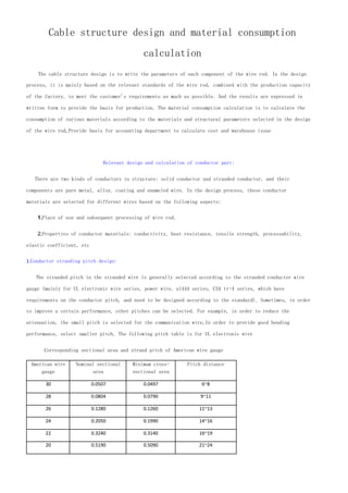
performance, select smaller pitch. The following pitch table is for UL electronic wire
Corresponding sectional area and strand pitch of American wire gauge
American wire
gauge
Nominal sectional
area
Minimum cross-
sectional area
Pitch distance
30 0.0507 0.0497 6~8
28 0.0804 0.0790 9~11
26 0.1280 0.1260 11~13
24 0.2050 0.1990 14~16
22 0.3240 0.3140 16~19
20 0.5190 0.5090 21~24
2. 18 0.8230 0.8070 27~32
16 1.3100 1.2700 32~38
14 2.0800 2.0200 39~47
2.Calculation of outer diameter of multiple stranded conductors:
Conductor stranding shall be carried out by means of bundle stranding, and the outer diameter of stranding
shall be calculated by the following two methods:
Method 1:
Method 2:
D -- diameter ofsingle conductor
D --- outer diameter of strandedconductor after stranding
N --- number of conductors
Among the above two methods, method 2 is more suitable for the calculation of outer diameter of stranded conductor
3.Calculation of conductor quantity:
1.Single conductor
2.Stranded conductor
D --- diameter of single conductor
ρ - conductor density
N --- number of strandedconductors
λ - conductor stranding coefficient
3. Note: the quantity of conductor is calculated as the quantity of single core, and the stranding
coefficient of core wire shall be considered when multi-core
4.The conductor is resistant to oxidation http://www.tksiliconerubbercable.com
In order to prevent conductor oxidation, bat or DOP oil (such as power line and transparent line) can be
added when conductor is stranded.
Design and calculation related to the mortgaged part:
The extrusion part includes insulation extrusion, internal extrusion and external extrusion. In the
process of extrusion, the extrusion method is adopted due to different requirements of wire rod. Generally,
the extrusion method is adopted for insulation extrusion, and the half extrusion method is adopted for the
inner and outer protective layers. Sometimes, the extrusion method is adopted to meet the performance
requirements. For the specific selection method, refer to the extrusion technology
1.Selection of charging material:
In the process of design, the selection of extrusion material is mainly based on the use of rubber
material, temperature resistance grade, luster, soft hardness, migration resistance of plasticizer, non-
toxic performance, etc
2.Outer diameter:
D2=D+2*T
D ------ outer diameter before extrusion
D2 ---- outer diameter after extrusion
T ------ thickness to be charged out
Extrusion thickness (T) is mainly based on the relevant standards of wire rod, combined with the
production capacity of the plant equipment to meet customer requirements as far as possible
3.Rubber content:
The calculation formula of the amount of rubber material is different with different methods
Squeezing tube type
Extrusion type
W = (s finishedsection - s cable core content) * ρ
ρ - density of rubber
4. Considering the tolerance of wire rod, the following calculation method is generally adopted by cable
enterprises in current period
W=3,14159*1.05*T*(2*D+T)* ρ http://www.tiankangcable.com
Relevant design and calculation of core stranding:
Core wire stranding is known as cable forming in China, which is one of the important processes
in the production of most multi-core cables.The process of stranding several insulated cores or
unit groups into cable cores is called core stranding.Its principle is similar to that of
conductor stranding, calculation of general process parameters of core wire stranding and
deformation of core wire in stranding process.According to the same diameter of stranded
insulated wire core, the core stranding can be divided into symmetrical stranding and asymmetric
stranding.Because the core wire has bending deformation in the process of stranding, some thicker
insulated core wires adopt untwisting in the process of stranding.Such as ul2919, cat. 5,
IEEE1394, DVI core and other high foaming insulation core.The calculation of technological
parameters of core wire stranding is described in the following aspects:
1.Pair:
Equivalent outer diameter of the pair:
D = 1.65d or 1.71d
(1.65d for soft, 1.71d for hard), sometimes d = 1.86d
Equivalent outer diameter of complex twisted pair:
D=2.6d
Equivalent outer diameter of multi pair stranded wire:
Pair pitch
According to the pairs of pairs, the outer diameter of core wire shall be selected
2. Multi core stranding:
When the number of cores is not large, the outer diameter of stranding shall be calculated according
to the normal stranding. See the table below
The arrangement of cores and the calculation of the outer diameter of cores can be based on the
following table:
Core number Core alignment Outer diameter ratio
(M = D / D)
Middle core void
area xd2
Outer void area xd2
6. 38 1+7+12+18 7.3 0 3.458
39 2+6+12+18 8 0 4.705
40 2+7+12+19 8 0 4.254
41 2+7+13+19 8 0 4.254
42 2+8+13+19 8 0 4.254
44 2+8+14+20 8 0 3.774
45 3+8+14+20 8.154 0.04 4.042
48 3+9+15+21 8.154 0.04 2.867
When the number of cores is large and the wire diameter is small, it can be calculated approximately
according to the strand (calculation formula of outer diameter of conductor strand)
Stranding pitch
Generally, the stranding pitch is 15-20 times of the outer diameter of the stranding. Sometimes, in
order to improve the performance of the wire, the appropriate pitch can be selected. For example, in order
to improve the bending performance of the wire and reduce the stranding pitch. In order to reduce the core
deformation of the USB cable, the large pitch is used http://www.chinathermocouple.com
3. About the diameter of base circle, pitch circle and outer diameter of stranding
Base circle diameter: for a strand layer, the diameter of the core wire before the strand is called the base
circle diameter
Pitch diameter: the diameter of the pitch circle is the circle whose radius is the distance between the
axis of the single wire and the axis of the stranded wire, and whose diameter is the pitch circle diameter
Stranding outer diameter: the outer diameter of this layer of strand is the outer diameter of the strand
For the third layer of stranding: the diameter of the base circle is d0 (that is, the outer diameter
of the stranding of the second layer (1 + 6))
Pitch diameter is d 'd' = d0 + D
The outer diameter of stranding is d d = D '+ D
7. 4.Twist in factor:
The stranding coefficient of core wire stranding is the quadratic of 1 + (PI x stranding od /
stranding pitch)
D ---- outer diameter of stranding
H ---- stranding pitch
In the process of stranding, for the case of multi-core parallel wire layering, although it is stranded,
the core wire stranding coefficient of each layer is not the same. For the sake of conservatism, increase
the safety factor In the calculation of the above-mentioned stranding coefficient, D adopts
the outer diameter of the core stranding (theoretically, the stranding coefficient of each layer should be
the pitch diameter substituted into the above formula)
The design and calculation of oblique package
The oblique wrapping wire mainly plays the role of shielding, sometimes as the outer conductor of
coaxial cable.
The purpose of shielding is to eliminate the external dry deflection. For coaxial cable, the impedance
can be matched due to the shielding layer, so as to reduce the loss of signal or transmission energy.
As far as shielding effect is concerned, oblique wrapping is not as good as knitting. Its shielding
effect has directionality. Shielding characteristics change when bending, but it has the characteristics of
small outer diameter, soft wire and low price.Suitable for low frequency shielding.The following describes
the design of inclined bag structure from several aspects:
1.Approximate calculation of the number of copper wires in inclined package:
Integral part
D -- outer diameter before oblique wrapping
D -- diameter ofinclinedcopper wire
If it is two or three core stranding, it is not round after stranding, and the outer diameter of D (before
inclined wrapping) is the equivalent outer diameter.
In this design, the outer diameter before the d-skew wrap is equal to the diameter of the base circle
in the strand.Theoretically speaking, pitch diameter should be used to achieve 100% skew wrap D, but in
order to prevent overfilling (easy to rise) due to less pitch selection and other factors.Therefore, D
adopts the outer diameter (base circle diameter) before the oblique packing.In the actual production,
because the inclined copper wire is generally 0.10 mm, 0.12 mm thin wire, its value is ignored in the above
8. calculation.According to the above formula, the skew wrap fullness can reach more than 90%, which has little
effect on the properties of wire rod.
2.The selection of pitch of inclined packing:
The pitch of inclined ladle is selected according to the size of outer diameter before the inclined
ladle, and is generally selected according to the following optimized pitch (this optimized pitch takes into
account cost, adhesion, appearance and other aspects, and has been verified by long-term production).
Pitch of outer diameter of finished product
D<1.0mm About 15.5mm
1.0<=d<1.2mm About 18mm
1.2<=d<2.0mm About 22mm
2.0<=d<2.2mm About 25mm
2.2<=d<2.4mm About 27mm
2.4<=d<3.0mm About 32mm
3.0<=d<3.5mm About 36mm
3.Twist in factor:
The twist in coefficient of skew pack is the quadratic of 1 + (PI x outer diameter / pitch of skew
pack)
D ---- outer diameter after oblique packing
H ---- pitch of inclined bag
4.Quantity of inclined copper wire:
D -- diameter ofinclinedcladconductor
ρ - density of inclined clad conductor
N --- number of inclined wrapped conductors
λ - twist in coefficient of inclined clad conductor
5.Direction selection of inclined bag
Generally, the oblique wrapping is in the opposite direction of the cable forming: in the production
process of oblique wrapping wire, the rotation direction of oblique wrapping copper wire is opposite to
that of the front material of oblique wrapping. If the oblique wrapping direction is the same as that of
9. the cable forming, the cable forming wire will be twisted first in the oblique wrapping process to make
the wire loose, so that the oblique wrapping is prone to be defective.However, it is relatively hard and
has poor bending performance.For those cables with less cores and larger core diameter, wires without
isolation layer can only be used in the opposite direction of the cable.
6.The oblique wrapped wire is extruded outside:
The slant wrapped wire rod shall pass through the reverse shaft before being pressed out to prevent the
broken wire from breaking when it is pressed out of the eye mold
Design and calculation of knitting
Braiding is similar to oblique wrapping, which mainly plays a shielding role in the wire, prevents the
influence of external electric field and magnetic field, and improves the degree of dry deflection defense
of wire rod. Compared with oblique wrapping and aluminum foil, it has the following characteristics:
1.Shielding is not directional
2.High frequency shielding features are good, suitable for high frequency shielding
3.Through multilayer shielding, the shielding effect can reach 100%
4.There is no change in shielding characteristics when bending
1.Calculation formula related to weaving:
Weave angle tangent:
Weaving coefficient:
Weaving density:
Weaving amount:
H -- braidedpitch
10. D -- diameter ofbraided single wire
A ----- number of wovenhalf blooms
N ---- number of braided parallel wires
α - braiding angle
2.Determination of weaving parameters:
1.Select the type of braiding machine (16 or 24 spindle high and low speed braiding machine) according to
the outer diameter of cable core and the braiding density
2.Select the braided single copper wire suitable for the braiding machine (tinned or bare copper wire Φ
0.08mm, Φ 0.10mm, Φ. 12mm).
3.Density M. braiding angle α. Determination of pitch H
Note: the number of wires in each ingot should be within the range of 3-9. Because the number of wires
is less, and the number of wires is too much, the copper wires in the same layer of the braiding
layer overlap. The braiding angle is usually within the range of 50-70. In order to improve the
production efficiency, the braiding angle is close to the value of 70. The above formula is used to
budget the parameters, and the appropriate braiding number, braiding angle, braiding pitch
determined by the rounding algorithm are usedWeaving density.The weaving calculation in the
calculation part is based on the above formula and the enumeration method
Other structural design and calculation:
In order to improve the quality of wire, other materials should be added in the design of wire.In
order to make the wire round, the filler is added when the core wire is stranded; in order to prevent the
conductor from oxidation, b.t.a is coated on the surface of the conductor when the conductor is stranded,
DOP or silicone oil is coated on the surface of the conductor when the wire adhesion insulation is extruded,
and talcum powder or mica powder is dragged on the surface of the core wire when the outer wire is
extruded.The following are classified and described according to their functions:
1.Filler design and calculation:
The fillings mainly include cotton yarn and PP rope. During the design, cotton yarn, PP rope or other
fillings are mainly selected according to the filling gap size, wire performance requirements and material
use place.
Calculation of the number of fillers
N = (s gap / s single filling) integer part
Amount of filler
W = weight of single piece * n * λ
11. λ - is the stranding coefficient of core wire stranding
2.Design and calculation of isolation layer:
Selection of isolation materials: paper tape only plays a role of separation in the online material;
aluminum foil has a role of separation and shielding in the online material.When the wire only needs to be
separated, paper tape shall be used; otherwise, aluminum foil shall be used.Sometimes in some high-
performance communication lines, the isolation layer adopts non-woven fabric or foamed PP tape (such as
SISC)
Process mode
In the manufacturing process of the separation layer, in order to save working hours, three different
ways of wrapping, dragging and longitudinal wrapping can be adopted according to the situation
Material consumption
N -- number of isolationlayers
T refers to the thicknessof isolationbelt
ρ - density of isolation material
K refers to the overlapping rate ofisolation belt
3.Relevant calculation of stranding rate:
M is the pitch diameter ratio
H ------ pitch
D ------ outer diameter of wire strand
Note 1: the above calculation of stranding coefficient is the calculation of one process. In the
actual calculation of volume, the whole production process should be considered, so the total stranding
coefficient may be the product of stranding coefficient of multiple processes
Note 2: the lower limit value of pitch range shall be taken in design calculation to strive for the
maximum stranding coefficient in the quota (while adopting the value close to the maximum pitch value in
production will not only improve efficiency, but also reduce the material consumption in normal production)
12. Electrical performance calculation part
With the rapid development of modern electrical communication industry, the electrical performance
requirements of wires and cables used for signal transmission are becoming higher and higher. Therefore,
when designing the structure of communication wire rod, the electrical performance of wire rod should be the
key consideration. The following part mainly introduces the basic theoretical calculation methods of
electrical and pneumatic performance of communication wire rod:
Calculation formula of equivalent dielectric constant of foaming insulation:
Foaming insulation is a kind of combined insulation, which is mainly to reduce the equivalent
dielectric constant of the insulating medium and improve the electrical performance of the wire rod.The
equivalent permittivity of foaming insulation medium is between that of air insulation and plastic
insulation. In the design process, the following two methods can be used to calculate the equivalent
permittivity of foaming insulation medium.
Methods (1):
The equivalent permittivity of ε - dielectric materials
P- foaming%%, which indicates the ratio ofthe volume ofall smallbubbles to the totalvolume ofinsulationin the foam
medium.
Methods (2):
D foam -- the specific gravityof foammedium
D material - specific gravityof mediummaterial itself
ε e -- dielectric constant of solid insulation
ε - dielectric constant of foaming insulation
Structural calculation of symmetrical cable:
13. Symmetrical communication cable is composed of many insulated cores, which are twisted into a
composite cable core and then wrapped with a protective layer. One or more pairs of insulated
cores with the same outer diameter and the same structure are arranged symmetrically to the
ground, so it is called symmetrical cable.The conductive core of symmetrical cable is used to
guide the transmission direction of electromagnetic wave. Therefore, it is required to ha ve good
conductivity, good flexibility and sufficient mechanical strength, as well as the convenience of
processing, laying and use.
The following describes the main electrical performance of the symmetrical cable in terms of
primary transmission parameters and secondary transmission parameters:
1.Primary transmission parameters
R. L.c.g is called the primary transmission parameters of cable line: these parameters are independent of the voltage and
current of electromagnetic wave transmission, but related to the material structure of cable and the frequency of current:
1.1Effective resistance
Effective resistance is the resistance when AC flows through symmetrical circuit, including DC
resistance and additional resistance caused by AC
R has = R direct + R cross
R intersection = R neighborhood + R Set + R gold
λ - Total stranding coefficient
ρ - resistivity of conducting core ohm * mm2 / M
L ------ cable length m
S ------ sectional area of conducting wire core
D -- diameter of conductive core mm
14. A -- distance between centers of two conductors in the circuit mm
K ------ eddy current coefficient
U ------ permeability
σ ---- conductivity
For the calculation of H (x) f (x) g (x) k, please refer to page 50 of communication cable
1.2Inductance of symmetrical cable
When the loop current is alternating current, the magnetic flux will be generated in and
around the conductive core of the loop. The one inside the conductive core is called
internal magnetic flux, and the one outside the conductive core is called external magnetic
flux. The inductance is the ratio of the magnetic flux to the current causing the magnetic
flux, so the corresponding internal magnetic flux and external magnetic flux have internal
inductance L and external inductance L, and the total inductance is L = l internal + L
external. When the symmetrical circuit has a shielding layer,In addition to inductance L and
inner inductance L, there are additional inductors brought by shield to transmission circuit
1.2.1.Unscreened:
(H/Km)
λ - Total stranding coefficient
D -- diameter of conductive core mm
A -- distance between centers of two conductors in the circuit mm
K ------ eddy current coefficient
U ------ permeability
15. σ ---- conductivity
For the calculation of Q (x), please refer to page 54 of communication cable
1.2.2.Shielding:
(H/Km)
λ - Total stranding coefficient
D -- diameter of conductive core mm
A -- distance between centers of two conductors in the circuit mm
K ------ eddy current coefficient
U ------ permeability
σ ---- conductivity
For the calculation of Q (x), please refer to page 54 of communication cable
1.3Capacitance of symmetrical cable
The capacitance of the cable return is similar to that of the general capacitor. Two conductor
cores are equivalent to two electrodes, conductor wires
The insulation between the cores is equivalent to the dielectric between the capacitor plates
When the two conducting wire cores of the loop have an equal amount of anisotropic charge, the
ratio of the electric quantity Q of the charge to the potential difference u between the two
conducting wire cores is the capacitance of the loop, i.e. C = u / Q
The capacitance of symmetrical cable loop is relatively complex, because many pairs of wires are
often included in the cable, and there are shielding layers or metal sleeves outside. All
adjacent cores or cores and shielding layers will have capacitance. The capacitance between
loops refers to the sum of all parts
16. There are two kinds of capacitance in symmetrical cable circuit: working capacitance and partial
capacitance. The capacitance in primary transmission parameter refers to working capacitance
(working capacitance is composed of partial capacitance)
The capacitance of unshielded symmetrical cable (UTP) can be calculated as follows:
F/m
It is suitable for the ideal situation that two conductors are parallel to each other and there
are no other pairs around
A - center distance between two conductors (mm)
D - diameter of center conductor (mm)
Equivalent permittivity of ε e-insulating material
For symmetrical cables with many pairs of structures, the influence of wire pair stranding and
the equivalent factors of adjacent wires shall be considered, and their capacitance shall be
The calculation formula is:
F/m
λ - stranding coefficient
φ - correction factor, considering the influence of adjacent line pair or line pair shielding
layer on capacitance
The relationship between the correction coefficient φ and the structural parameters
Shielded twisted pair
Unshielded twisted pair
A ------ center distance of symmetrical cable conductor
17. DS ---- inner diameter of shielding layer (mm)
D2 -- outer diameter of twisted pair (mm)
D1 -- outer diameter of insulated core wire (mm)
1.4.Insulation conductance of symmetrical cable
The parameter of insulation conductance g indicates the quality of the insulation layer of
the cable core and the loss of electromagnetic energy in the core insulation. The insulation
conductance is determined by the characteristics of the insulation medium, that is, the
volume insulation resistance coefficient of the insulation medium and the tangent of the
dielectric loss angle. The insulation conductance G is a combination of the DC insulation
conductance G0 and the AC insulation G ~. The calculation formula is as follows:
G=G0+G~
G~=ω*Ctg(δ)
G0 ------ DC loss
G ~ ----- AC loss
ω ------ current frequency
C ------ working capacitance
TG (δ) - dielectric loss tangent
2.Secondary transmission parameters
Secondary transmission parameters are used to characterize the characteristics of transmission
lines, including characteristic impedance ZC, attenuation constant α, and phase-shift constant
2.1characteristic impedance
Characteristic impedance is the impedance encountered when the electromagnetic wave propagates
along the uniform cable line without reflection. Its value is only related to the primary
transmission parameters of the line and the frequency of the current, but not to the
length of the line, but also to the size of the transmission voltage and current and the
negative impedance
Unshielded symmetrical cable (UTP):
18. Europe
Europe
Shielded symmetrical cable (STP):
Europe
Europe
When the central conductor of symmetrical cable is stranded str ucture and the shield is braided,
the formula is as follows: Europe
K3 is the empirical correction coefficient of weaving influence, with the value of 0.98-0.99
K1 is the conductor correction coefficient, the relationship between the conductor structure correction coefficient K! And the
number of conductors:
Number of conductors in the
strand
N 1 3 7 12 19
Correction factor of inner
conductor structure
K1 1.000 0.871 0.939 0.957 0.970
Number of conductors in the
strand
N 27 37 50 70 90
Correction factor of inner
conductor structure
K1 0.976 0.980 0.983 0.986 0.988
2.2Attenuation:
Attenuation is one of the most important parameters of RF cable, which reflects the loss of
electromagnetic energy when it is transmitted along the cable. The attenuation of cable
indicates the loss degree of transmission power or voltage when the cable is working in
traveling wave state
The attenuation of symmetrical cable under RF can be calculated according to the simplified
formula of HF as follows:
2.2.1.Unshielded symmetrical cable:
19. 2.2.2.Shielded symmetrical cable:
F----- frequency
De -- electrical equivalent diameter of stranded conductor
D ---- outer diameter of stranded conductor
DS -- shielding inner diameter
A -- center distance of symmetrical cable conductor
ε e -- equivalent permittivity of insulation
TG (δ) - equivalent dielectric loss tangent of insulation
KP1 -- RF resistance coefficient of conductor, see table 4.5 in RF cable structure design
KP2 -- see table 4.5 in RF cable structure design for RF resistance coefficient of shielding
KS ------ resistance coefficient of stranded conductor 1.25
KB ------ resistance coefficient of braided shield 2.0
K3 ------ coefficient of influence of braiding on impedance 0.98-0.99
Calculation of electrical parameters of coaxial cable:
One circuit of coaxial cable is coaxial pair, which is asymmetric to the ground. Another circular
conductor (called inner conductor) is arranged in the metal circular tube (called outer conductor), and the
two are insulated with insulating medium to keep the axes overlapped, thus forming a symmetrical coaxial
pair.Coaxial cable can be used to open multi-channel wave planting communication or transmit TV programs,
and also can be used to transmit high digital data information (such as ul2919 screen cable)
1.Primary transmission parameters:
20. The primary transmission parameters of coaxial cable mainly change with the frequency of current and cable
structure size D / d
(1).The effective resistance increases with the increase of frequency, but has no direct relation
with the diameter ratio of inner and outer conductor
(2).The inductance decreases with the increase of frequency and increases with the increase of
diameter ratio of inner and outer conductor
(3).The capacitance is independent of frequency and decreases with the increase of diameter ratio
(4).The conductance is proportional to the frequency and decreases with the increase of the diameter
The specific calculation formula is as follows:
1.1.Effective resistance:
The effective resistance of the coaxial cable includes the effective resistance of the inner
conductor and the effective resistance of the outer conductor. When the inner and outer conductors
are copper conductors, the total effective resistance is:
(ohm / km)
1.2Effective inductance:
The inductance of the coaxial circuit consists of the internal inductance of the internal and
external conductors and the external inductance between the internal and external conductors. When the
internal and external conductors are copper, the inductance of the circuit is:
(Heng / km)
1.3Coaxial cable capacitance:
As the coaxial cable has no external electric field, the working capacitance of the coaxial pair is
equal to the partial capacitance between the inner and outer conductors of the coaxial pair. The capacitance
can be calculated according to the capacitance formula of the cylindrical capacitor:
21. DW correctioncoefficient of outer conductor structure (idealouter conductor DW = 0, non ideal outer conductor DW =
diameter of single wire inbraided outer conductor)
K1 correctionfactor of inner conductor structure,
D1 - inner diameter of outer conductor of coaxial line (mm)
1.4Insulation conductance:
The insulating conductor g of the coaxial pair consists of two parts: one is the alternating current
conductivity G ~ caused by the polarization of the insulating medium, the other is the direct current
conductivity G0 caused by the imperfect insulation
G=G0+G~
G~= Omega Ctg (delta)
G0 ------ DCloss
G ~ ----- ACloss
ω ------ current frequency
C ------ working capacitance
TG (δ) - dielectric loss tangent
2.Secondary transmission parameters:
Secondary transmission parameters are used to characterize the characteristic parameters of
transmission line, including characteristic impedance ZC, attenuation constant α, and phase-shift
constant
2.1.Characteristic impedance of coaxial cable:
2.1.1.For oblique cladding, the longitudinal cladding of aluminum foil can be regarded as an ideal
outer conductor, and the calculation is as follows:
2.1.2.The calculation of braided outer conductor and inner conductor of strand is as follows:
22. D --- outer diameter of outer conductor
D ---- outer diameter of inner conductor
DW -- diameter of braided conductor
K1 - correction coefficient of conductor structure
2.2Calculation formula for attenuation of coaxial cable:
α r-attenuation component caused by conductor resistance loss, conductor attenuation (resistance
attenuation)
When both inner and outer conductors are cylindrical:
Db/km
When the inner conductor is stranded and the outer conductor is braided:
Db/km
D. D ---- inner diameter of outer conductor andouter diameter of inner conductor
K1 -- conductor structure correctioncoefficient
ε - dielectric constant of insulation
KS refers to the coefficient ofincreasingthe resistance ofthe plane cable caused bythe strandedwire, KS = 1.25
KB -- coefficient of increase inresistance of plane cable causedbybraiding
DW -- diameter of single wire inbraidedouter conductor
KP1, KP2 - indicate that the RFresistance increases or decreases whenthe inner andouter conductors are different from the
standardsoft copper
23. Coefficient.
The weaving coefficient KB can also be calculated as follows:
M ---- number of spindleswoven
N -- number of wires in eachspindle of braidedwire
β - is the braid angle (the angle between the direction of braided wire and the direction of cable
axis)
α g --- attenuation component caused by dielectric loss, which is called dielectric attenuation
(conductance attenuation)
TG σ e -- tangent of equivalent dielectric loss angle
ε e ------ equivalent permittivity
2.3Delay:
Delay refers to the delay time per unit length of signal when it is transmitted along the cable
The delay time of coaxial cable is independent of cable size and only depends on the dielectric constant
of the medium
Seconds / meter
V -- propagationspeedof signal incable
ε e ---- equivalent permittivity