International Journal of Engineering Research and Development
Abstract_Vincent_Meertens
1. Simulation of the fluid flow around a planing
hull
Vincent Meertens
Abstract - This article describes the research of the flow around
a planing hull and the influences of modifications on the hull.
The main results are described in a comparison of the lift and the
drag.
I. SIMULATION
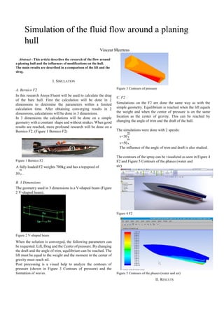
A. Bernico F2
In this research Ansys Fluent will be used to calculate the drag
of the bare hull. First the calculation will be done in 2
dimensions to determine the parameters within a limited
calculation time. After obtaining converging results in 2
dimensions, calculations will be done in 3 dimensions.
In 3 dimensions the calculations will be done on a simple
geometry with a constant shape and without strakes. When good
results are reached, more profound research will be done on a
Bernico F2. (Figure 1 Bernico F2)
Figure 1 Bernico F2
A fully loaded F2 weights 700kg and has a topspeed of
50 .
B. 3 Dimensions
The geometry used in 3 dimensions is a V-shaped beam (Figure
2 V-shaped beam).
Figure 2 V-shaped beam
When the solution is converged, the following parameters can
be requested: Lift, Drag and the Center of pressure. By changing
the draft and the angle of trim, equilibrium can be reached. The
lift must be equal to the weight and the moment in the center of
gravity must reach nil.
Post processing is a visual help to analyze the contours of
pressure (shown in Figure 3 Contours of pressure) and the
formation of waves.
Figure 3 Contours of pressure
C. F2
Simulations on the F2 are done the same way as with the
simple geometry. Equilibrium is reached when the lift equals
the weight and when the center of pressure is on the same
location as the center of gravity. This can be reached by
changing the angle of trim and the draft of the hull.
The simulations were done with 2 speeds:
v=30
v=50 .
The influence of the angle of trim and draft is also studied.
The contours of the spray can be visualized as seen in Figure 4
F2 and Figure 5 Contours of the phases (water and
air)
Figure 4 F2
Figure 5 Contours of the phases (water and air)
II. RESULTS
2. When modifications are done to the hull, the results can be
calculated in Fluent. The lift, drag and center of pressure are
compared to the original F2.
Both hulls have to reach equilibrium before being compared.
The results show that modifications done to the hull can
decrease drag by 15% in a passive way.
The graphics (Figure 6 Lift and Figure 7 Drag) show a
comparison of the original hull and the modified hull.
Lift
Figure 6 Lift
Figure 7 Drag
3000
3100
3200
3300
3400
3500
3600
F2 F2_U2
350
370
390
410
430
450
470
Drag
F2 F2_U2