Descarrilamiento de tren
•
0 likes•127 views

Improving Forensic and Analytical Capabilities with the FARO Laser Scanner

Recommended
Recommended
More Related Content
Similar to Descarrilamiento de tren
Similar to Descarrilamiento de tren (20)
More from Ulises Uscanga
Recently uploaded
Recently uploaded (20)
Descarrilamiento de tren
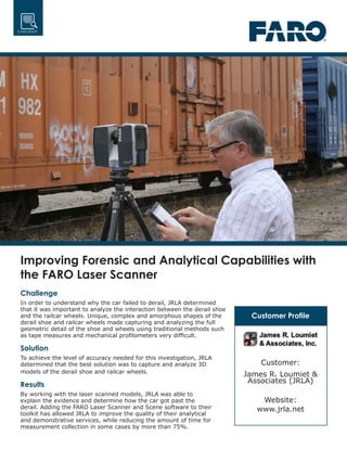
- 1. Customer Profile Customer: James R. Loumiet & Associates (JRLA) Website: www.jrla.net CASE STUDY Challenge In order to understand why the car failed to derail, JRLA determined that it was important to analyze the interaction between the derail shoe and the railcar wheels. Unique, complex and amorphous shapes of the derail shoe and railcar wheels made capturing and analyzing the full geometric detail of the shoe and wheels using traditional methods such as tape measures and mechanical profilometers very difficult. Solution To achieve the level of accuracy needed for this investigation, JRLA determined that the best solution was to capture and analyze 3D models of the derail shoe and railcar wheels. Results By working with the laser scanned models, JRLA was able to explain the evidence and determine how the car got past the derail. Adding the FARO Laser Scanner and Scene software to their toolkit has allowed JRLA to improve the quality of their analytical and demonstrative services, while reducing the amount of time for measurement collection in some cases by more than 75%. Improving Forensic and Analytical Capabilities with the FARO Laser Scanner
- 2. Improving Forensic and Analytical Capabilities with the FARO Laser Scanner 2 CASE STUDY Figure 1. Derailed freight car carring lumber products collided with an MBCR commuter train “Laser scanners aren’t just for large engineering firms with big budgets, but also for small companies who want to provide their clients with state-of-the-art services and technology that in many cases exceed those of larger competitors.” James Loumiet, President of James R. Loumiet & Associates. As one of the first accident reconstruction firms in the U.S. to own and implement a laser scanner for reconstructing railroad accidents, James R. Loumiet & Associates (JRLA, www.jrla.net) provide consulting and expert witness services to the legal, insurance and transportation industries. Located in Independence, Missouri, JRLA specializes in train and traffic accident reconstruction, highway safety analysis, vehicle event data recorder analysis, 3D laser scanning, and computer simulation of trains and collisions. In a recent train accident case, JRLA was retained by Massachusetts Bay Commuter Rail (MBCR), a commuter railroad in Boston, to determine how a parked 130-ton freight car carrying lumber products broke loose and rolled past a derail onto a main line track, where it collided with an MBCR commuter train, injuring a number of passengers (Figure 1). A derail is a track appliance placed on a rail, designed to derail a car in the event it gets loose. In this case, a derail was reportedly placed on the industry track between the freight cars and the main line track. After the accident, investigators examined the derail and found it in the OFF position. However, when the wheels of the freight car were inspected, paint from the derail was found on the two lead wheels of the car, yet no paint transfer was present on the two rear wheels. Since the geometry of the derail device was designed to redirect and deflect a railcar wheel off the rail when a wheel rolls over the device, JRLA was tasked with analyzing why the device had failed to derail the car if it had initially been placed in the ON position on the rail, and if it had been placed correctly on the rail, how the car had gotten past it.
- 3. Improving Forensic and Analytical Capabilities with the FARO Laser Scanner 3 CASE STUDY Analyzing the evidence in the 3D environment, JRLA was able to determine that the derail shoe had initially been placed on the rail, but not fully across the top of the rail, leaving about one inch of the top of the rail exposed... By working with the laser scanned models, JRLA was able to explain the evidence and determine how the car got past the derail. The challenge Effectively analyze the interaction between the derail shoe and the railcar wheels Designed to prevent unauthorized movements or unattended rolling stock from reaching a main line track, the main component of a derail is called the shoe, which is a 24-inch long metal casting that rests on top of the rail. In order to understand why the car failed to derail, JRLA determined that it was important to analyze the interaction between the derail shoe and the railcar wheels (Figure 2). However, the unique, complex and amorphous shapes of the derail shoe and railcar wheels made capturing and analyzing the full geometric detail of the shoe and wheels using traditional methods such as tape measures and mechanical profilometers very difficult. The solution Collect 3D models of the derail device, a section of the rail, and the freight car wheels using a FARO Laser Scanner. To achieve the level of accuracy needed for this investigation, JRLA determined that the best solution was to capture and analyze 3D models of the derail shoe and railcar wheels. Enlisting the help of Direct Dimensions, Inc. to assist with the scanning, JRLA was able to collect 3D models of the derail device, a section of the rail, and the freight car wheels using a FARO Laser Scanner. The 3D models allowed them to bring the scanned objects into a 3D environment to analyze the interaction between the wheels, derail shoe and rail. Analyzing the evidence in the 3D environment, JRLA was able to determine that the derail shoe had initially been placed on the rail, but not fully across the top of the rail, leaving about one inch of the top of the rail exposed (Figure 3). When the freight car got loose and rolled over the derail, the lead wheel mounted the shoe, and was deflected onto the top of the rail. However, instead of the wheel derailing, it re-railed itself past the derail shoe and continued rolling. As a result of the wheel- derail interaction, paint from the derail was transferred onto the first wheel. Figure 2. Evidence of interaction between the derail show and the railcar wheels.
- 4. © 2016 FARO Technologies, Inc. All Rights Reserved. This case study is for informational puposes only. FARO makes no warranties–express or implied–in this case study. FARO, THE MEASURE OF SUCCESS and the FARO Logo are registered trademarks and trademarks of FARO Technologies, Inc. Reference number: SFDC_04MKT_0286.pdf Created: 2/2/12 CASE STUDY Improving Forensic and Analytical Capabilities with the FARO Laser Scanner View more of FARO’s case studies at www.faro.com The second wheel did the same thing, except when it re-railed, it was adjacent to the derail shoe and pushed the entire shoe off the rail, preventing the two rear wheels from ever touching it, explaining the lack of derail paint on the rear wheels. By working with the laser scanned models, JRLA was able to explain the evidence and determine how the car got past the derail. The result Return on investment Accident reconstruction creates a challenge in accurately documenting evidence in train and automobile collisions in a safe and useful manner. James Loumiet, President of James R. Loumiet & Associates said, “The decision to purchase a FARO Laser Scanner and FARO Scene software were based on their ability to provide our firm with forensic and analytical capabilities that were otherwise unavailable in competitive products.” Adding the FARO Laser Scanner and Scene software to their toolkit has allowed JRLA to improve the quality of their analytical and demonstrative services, while reducing the amount of time for measurement collection in some cases by more than 75% (Figure 4). For example, on a busy roadway with a lot of tire marks, it might take up to 4 hours to make rudimentary measurements and drawings. With the FARO Laser Scanner, these same measurements and a full 3D model can be generated in about a half- hour to an hour. Overall, the greatest value in using the technology provided by these additional tools has been the ability to provide state-of-the-art forensic services to their clients that few can match. As innovators in the railroad accident reconstruction industry, the company has come a long way in terms of integrating laser scanning into their processes and workflows. However, this could only be achieved with the help of FARO’s support along the way; according to Mr. Loumiet, “FARO’s service, support, and willingness to work with our company to help us integrate laser scanning into our forensic analysis services was another reason we went with FARO as opposed to another manufacturer. The support has been outstanding.” Figure 3. Analyzing the evidence in the 3D environment, JRLA was able to determine that the derail shoe had initially been placed on the rail, but not fully across the top of the rail, leaving about one inch of the top of the rail exposed. “FARO’s service, support, and willingness to work with our company to help us integrate laser scanning into our forensic analysis services was another reason we went with FARO as opposed to another manufacturer. The support has been outstanding.” James Loumiet, President of James R. Loumiet & Associates. Figure 4. JRLA utlized FARO laser scanners to improve the quality of their analytical and demonstrative services, while reducing the amount of time for measurement collection.