
Recommended
Recommended
More Related Content
Similar to Major Study Project Thesis
Similar to Major Study Project Thesis (20)
Recently uploaded
Recently uploaded (20)
Major Study Project Thesis
- 2. P a g e | 1 Tom Statters N0564392 Abstract This project identified and investigated the causes of drop foot in stroke survivors and the subsequent effects of prolonged periods of rehabilitation. Utilising a customised user centred design methodology, the needs of the user and a gap in the market for an Ankle Foot Orthosis providing bio-feedback on the user’s walking pattern were identified. A final design solution that fulfilled this clinical need was achieved following the support and feedback provided by the Nottingham Stroke Association (NSA). Qualitative and quantitative research methods were used to clearly define the user’s needs. This subsequently determined the Product Design Specification (PDS), derived from Pugh’s Total Design Method, which outlines in detail the required features of the product. The stroke survivors of the NSA proved invaluable throughout the design process, adopting the role of project clients and giving rich feedback that shaped the design. The PDS was also influenced by secondary research which looked into existing products and relevant technologies. User and expert feedback weighted the importance of each element of the PDS. Multiple concepts were generated to cover a broad range of possible solutions, these were subsequently evaluated through the Combinex evaluation method, to determine the most suitable designs for further development. Recurring user feedback influenced the developments made to the design. The final design solution was created using SolidWorks 2017 CAD software, in order to determine overall form and weight of each of the products components. This data was subsequently used to define a realistic final costing of the product. The final outcome of this project successfully delivers a viable user centred design solution that incorporates bio-feedback and innovative design to reduce the time spent in rehabilitation for drop foot sufferers.
- 3. P a g e | 2 Tom Statters N0564392 Acknowledgments There are a number of individuals that deserve a great deal of thanks and recognition for their efforts to aid and assist this project, without them it would not have been possible. Firstly, I’d like to thank all the member at the Nottingham Stroke Association for their support and cooperation throughout the project. Their knowledge formed invaluable user feedback at all stages of the process. Thanks also to Professor Philip Breedon and Luke Siena for the constructive advice and guidance throughout all stages of the project. Finally, I would like to thank my mother, Sian Statters, for her continual advice and support during this academic year.
- 4. P a g e | 3 Tom Statters N0564392 Table of Contents Chapter 1- Design in Context ............................................................................................. 8 1.1- Introduction ............................................................................................................................ 8 1.2- Background ............................................................................................................................. 8 1.3- The Brief ................................................................................................................................. 8 1.4- Aims and Objectives ............................................................................................................... 9 1.4.1- Project Aim .......................................................................................................................... 9 1.4.2- Product Aim ......................................................................................................................... 9 1.4.3- Project Objectives ................................................................................................................ 9 1.5- Conclusion .............................................................................................................................. 9 Chapter 2 – Research Methodology ................................................................................. 10 2.1- Introduction .......................................................................................................................... 10 2.2- Research Methodology ........................................................................................................ 10 2.3- Designing for Disability ......................................................................................................... 11 2.3.1- Drop Foot ........................................................................................................................... 11 2.3.2- Drop Foot Rehabilitation ................................................................................................... 13 2.4- Interviews-Thematic Analysis ............................................................................................... 14 2.4.1- Evaluation of Interviews .................................................................................................... 14 2.4.2- User Feedback- Nottingham Stroke Association - Focus Group ........................................ 14 2.4.3- Expert Feedback ................................................................................................................ 15 2.4.4- Conclusion of Interviews ................................................................................................... 16 2.5- Existing Products .................................................................................................................. 17 2.5.1 AFO Analysis ....................................................................................................................... 17 2.5.2- Knowledge gained from existing product analysis ............................................................ 18 2.6- Time Management ............................................................................................................... 19 2.6.1- Gantt chart ........................................................................................................................ 19 2.6.2- Critical Path Analysis ......................................................................................................... 20 2.7- Technology Research ............................................................................................................ 22 2.7.1- Force Sensors .................................................................................................................... 22 2.7.2- Initial Test .......................................................................................................................... 23 2.7.3- Foot Force Sensor Test ...................................................................................................... 24 2.7.4- Accelerometers & Gyroscopes .......................................................................................... 26 2.7.5- Arduino Boards .................................................................................................................. 26 2.8- Conclusion ............................................................................................................................ 26 Chapter 3- Design Considerations .................................................................................... 27 3.1- Introduction .......................................................................................................................... 27 3.2- Ergonomics ........................................................................................................................... 27 3.2.1- Gait Abnormalities caused by drop foot ............................................................................ 28 3.3- Anthropometrics .................................................................................................................. 29 3.3.1- Conclusion ......................................................................................................................... 31 3.4- Standards and Regulations ................................................................................................... 31 3.5- Intellectual Property (IP) ...................................................................................................... 32 3.6- Product Design Specification (PDS) ...................................................................................... 33 3.7- Conclusion ............................................................................................................................ 34 Chapter 4- Design Process ............................................................................................... 35 4.1- Introduction .......................................................................................................................... 35 4.2- Design Methodology ............................................................................................................ 35 4.2.1- Chosen Design Method ..................................................................................................... 35 4.2.2- Design and Development Route ........................................................................................ 37
- 5. P a g e | 4 Tom Statters N0564392 4.3- Shell & Function Concepts .................................................................................................... 38 4.3.1- Concept 1 .......................................................................................................................... 38 4.3.2- Concept 2 .......................................................................................................................... 39 4.3.3- Concept 3 .......................................................................................................................... 40 4.3.4- Concept 4 .......................................................................................................................... 41 4.3.5- Concept 5 .......................................................................................................................... 42 4.3.6- Concept 6 .......................................................................................................................... 43 4.5- User rated Combinex- Concept Evaluation .......................................................................... 44 4.6- Expert rated Combinex- Concept Evaluation ....................................................................... 45 4.8- Conclusion: User feedback and evaluation of initial concepts ............................................. 45 Chapter 5- Design Development ...................................................................................... 46 5.1- Introduction .......................................................................................................................... 46 5.2- Ankle Hinge Development .................................................................................................... 46 5.3- Ankle stopper & Fastening ................................................................................................... 47 5.3- Pressure Sensor Development ............................................................................................. 48 5.3.1- Force Sensor Testing ......................................................................................................... 48 5.3.2- Electrical Component Housing .......................................................................................... 49 Chapter 6- Materials and Manufacture ............................................................................ 50 6.1- Introduction .......................................................................................................................... 50 6.2- Material Selection Method ................................................................................................... 50 6.2.1- AFO Main Body .................................................................................................................. 50 6.2.2- Sole Cover material selection ............................................................................................ 51 6.2.3- Conclusion ......................................................................................................................... 51 6.3- Method of Manufacture ....................................................................................................... 52 6.3.1- Critical review of methods ................................................................................................. 52 6.3.2- 3D Scanning ....................................................................................................................... 53 6.3.3- CNC Machining .................................................................................................................. 53 6.3.4- Vacuum Forming ............................................................................................................... 53 6.3.5- Set size model .................................................................................................................... 54 6.4- Parts List / Costing ................................................................................................................ 55 6.4.1- Introduction ....................................................................................................................... 55 6.4.2- Materials & Components .................................................................................................. 55 6.5- Conclusion ............................................................................................................................ 55 Chapter 7- Final Design Solution ...................................................................................... 56 7.1- Introduction .......................................................................................................................... 56 7.2 RecuperGAIT™ - Smart Foot Drop Recovery AFO .................................................................. 56 7.3- RecuperGAIT™ - Smart Foot Drop Recovery AFO- Design Features ..................................... 56 7.3.1- Introduction ....................................................................................................................... 56 7.3.2- Smart Technology .............................................................................................................. 57 7.3.4- User Interface .................................................................................................................... 57 7.4- PDS Evaluation ...................................................................................................................... 59 Chapter 8- Conclusion & Further Work ............................................................................ 60 8.1- Further Work ........................................................................................................................ 60 References ...................................................................................................................... 61
- 6. P a g e | 5 Tom Statters N0564392 List of Figures: Figure 2.1- Drop foot diagram Figure 2.2- Tibialis Anterior Muscles & Peroneal nerve (Inner Body, 2015) Figure 2.3- Critical Path Analysis flow diagram Figure 2.4- Heel force test result Figure 2.5- SingleTact Pc Digital Setup Figure 2.6- Diagram of parts of foot tested (Author) Figure 2.7- Foot force sensor test result graph for participant 3 (Author) Figure 2.8- 450 N Force sensor testing Figure 3.1- Gait Cycle Diagram Figure 4.1- Design Methodology (Author) Figure 4.2- Design and Development Route (Author) Figure 4.3- Concept 1 initial sketches Figure 4.4- Concept 2 initial sketches Figure 4.5- Concept 3 initial sketches Figure 4.6- Concept 4 initial sketches Figure 4.7- Concept 5 initial sketches Figure 4.8- Concept 6 initial sketches Figure 4.9- User rated Combinex graphs Figure 4.10- Expert rated Combinex graphs Figure 5.1- Ankle Hinge render (Author) Figure 5.2- Ankle stopper & fastening render (Author) Figure 5.3- Pressure sensor matrix render (Author) Figure 5.4- Electrical Component Housing render (Author) Figure 6.1- 3D Scanning leg for bespoke AFO Figure 6.2- Placing PP sheet over mould Figure 7.1- Final Design Render (Author) Figure 7.2- User app interface Figure 7.3- Render of final AFO
- 7. P a g e | 6 Tom Statters N0564392 List of Tables: Table 2.1- Causes of drop foot Table 2.2- Treatments for Drop Foot Table 2.3- Symptom of stroke survey- taken at Nottingham Stroke Club Table 2.4- Weighted importance of AFO features Table 2.5- Existing product research summary Table 2.6- Gantt chart Table 2.7- Critical path analysis breakdown Table 2.8- Force Sensor Analysis Table 2.9- Foot force sensor participants Table 2.10- Arduino Board comparison analysis Table 3.1- Gait abnormalities caused by drop foot Table 3.2- Ankle motion abnormalities caused by drop foot Table 3.3- Anthropometric data for British Adults Aged 19 to 65 Years Table 3.4- Anthropometric data for British Adults Aged 65 to 80 Years Table 3.5- Set sizes for AFO Table 3.6- IP analysis Table 3.7- PDS List of Headings Table 3.8- Product Design Specification Table 4.1- User rated Combinex results for Shell and Function concepts (Author) Table 4.2- Expert rated Combinex for Shell and Function concepts (Author Table 6.1- Material analysis of main body Table 6.2- Sole cover material analysis Table 6.3- Critical review of manufacturing methods Table 6.4- Materials & components cost and weight Table 6.5- Total one off manufacture cost
- 8. P a g e | 7 Tom Statters N0564392 Glossary of Terms: • Bio-feedback: biological signals that are fed back to the patient in order for the patient to develop techniques of manipulating them • Dorsiflexion: movement at the ankle joint that points the foot upwards. • Drop foot: Partial or total inability to dorsiflex the foot, causing toes to drag on the ground while walking. • Gait: the manner or style of walking • Plantar flexion: movement at the ankle joint that points the foot downwards.
- 9. P a g e | 8 Tom Statters N0564392 Chapter 1- Design in Context 1.1- Introduction The aim of this project was to address an issue that millions of individuals have to deal with worldwide, devise an initial idea and create a fully functioning and commercially viable product which is ready for market. The following brief was chosen in order to improve the speed and quality of rehabilitation for people suffering from drop foot, a symptom of several neurological disorders. Appendices in this document have been referenced throughout and should be referred to in order understand the research conducted. 1.2- Background Drop foot is a relatively simple name for a potentially complex problem. It can be defined as the inability to lift the front part of the foot, causing the toes to drag along the ground while walking (Pritchett, 2016). Drop foot can be a consequence of injury to the muscles in the front of the lower leg, injury to certain nerves, brain injury, stroke and even diabetes (Douglas, 2005). Stroke is the largest cause of complex disability in the UK, with over half of all the 1.2 million stroke survivors being left with this drop foot. (Stroke Association, 2016) In order to prevent toes from dragging, people with drop foot are prone to lifting their knee higher than normal or they may swing their leg in a wide arc (Retin, 2016). These coping mechanisms can hinder recovery as a natural gait pattern is not being used. This can lead to prolonged periods of rehabilitation, and therefore this project will explore the ways in which the quality of rehabilitation can be improved by providing bio-feedback data to the user. The design of a novel ankle foot orthosis will provide opportunities for the data to be monitored and analysed by the user and their physiotherapist in order to adapt their rehabilitation regime to their specific requirements. This information will increase the speed of recovery which is a huge benefit to the patient and the overstretched health service. This identifies a clear and tangible clinical need for this product. 1.3- The Brief The brief was to design a new ankle foot orthosis that is adaptable to wearers wanting assisted dorsiflexion and restricted plantarflexion, providing a natural and supported gait pattern for the wearer. Dorsiflexion is the upwards movement of the front of the foot, whereas plantarflexion is used to describe the downwards movement of the foot as it passes 90 degrees. The product designed must also provide live biomechanical feedback data, through the inclusion of smart technologies, in order to provide the patient and their physiotherapist with information used to adapt and improve gait pattern during rehabilitation.
- 10. P a g e | 9 Tom Statters N0564392 Essential Design Considerations: • AFO must gather real time biomechanical data • Data must be effectively displayed to user and physiotherapist • Must not encumber user • Must be affordable • Offer technologies and features not currently on the market 1.4- Aims and Objectives 1.4.1- Project Aim The aim of this project is to reduce the time spent by drop foot sufferers in rehabilitation, through the development of a novel pressure mapping orthosis. 1.4.2- Product Aim The aim of the product is two-fold, it must: • Provide the user with biomechanical feedback in the form of a visual pressure map and gait analysing data. • Provide adequate support to the user when walking on flat, declining and inclining ground. 1.4.3- Project Objectives • Undertake primary and secondary research into symptoms of stroke and the corresponding rehabilitation to identify a problem. • Conduct market research on existing products and assess appropriate costing and implementation factors. • Identify a range of medical conditions that would benefit from an AFO that accommodates dorsiflexion and plantarflexion. • Conduct research alongside rehabilitation specialists and potential users to inform the design process and product development. • Undertake concept development and prototyping to demonstrate a practical output. 1.5- Conclusion Research will be conducted looking to identify a clinical need for an adaptable Ankle Foot Orthosis that provides biomechanical feedback to the user and the physiotherapist that can be analysed and used to adapt rehabilitation exercises and targets. The aims and objectives that were identified used were throughout to ensure the project remained structured and true to its original goals.
- 11. P a g e | 10 Tom Statters N0564392 Chapter 2 – Research Methodology 2.1- Introduction Chapter 2 will outline the various elements of primary and secondary research undertaken as throughout the project. As well as detailing research methodologies utilised to create a suitable design solution. 2.2- Research Methodology An effectively utilised research methodology can considerably improve the quality of any project. Appendix C outlines the different methods that were explored and scrutinised. Primary research in the form of semi-structured and open interviews proved very effective, when used in conjunction with one another, to provide detailed qualitative data about the user’s needs. Whilst qualitative methods of research, including user and expert interviews, were applied to gain rich data from the user, quantitative methods, such as surveys and user weighted matrices, were undertaken to gain numerical data that would strengthen the case of this project further. In order to ensure that the project’s aims and objectives were met comprehensively, a user centred research approach was utilised. The use of primary research has proved very effective when it comes to defining the project brief and aims in the early stages of the project. Secondary research has provided the theoretical backing to the projects aims and objectives, offering important information that supported the product design specification alongside user feedback and evaluation. Below are the research methods used during the discovery stage of the project: • Drop Foot Rehabilitation statistics • Existing product analysis • Patent searches • Identify gap in market • Observe user walking habits • Gain information from physiotherapist • Research anatomy and physiology • Ergonomics and anthropometrics
- 12. P a g e | 11 Tom Statters N0564392 2.3- Designing for Disability Due to the improvements in technology and medical knowledge in the last century, demographic trends are showing that the number of over-60 group will continue to increase in Europe, North America, Australia and Japan, this will have significant implications on the design world (Schrott, 2009). The conditions that cause drop foot, such as stroke and motor neurone disease, mainly affects people in their 60s and 70s, however they can affect adults of all ages. This device will reduce the needless time spent going to the physiotherapist, thus enabling them to spend their time more effectively on other patients. There are approximately 152,000 strokes in the UK every year, which equals more than one every five minutes. There are approximately 1.1 million stroke survivors in the UK, more than half of all stroke survivors are left with a disability making stoke a leading cause of adult disability (Stroke Association, 2013). 2.3.1- Drop Foot Drop foot can be defined as a gait abnormality associated with weakness or paralysis of the muscle groups involved in in lifting of the foot during walking. Dorsiflexion is the movement of the toes up towards the front of the shin as a result of the tibialis anterior muscle shortening. With their weakened muscles the individual is prone to drag their foot along the floor or swing their whole leg from the hip. These gait abnormalities can increase the likelihood of falling down and causing further injuries. (Pritchett, 2016). This product will improve the quality of life for those suffering with drop foot as a more effective rehabilitation will allow them to become active and not develop other conditions as a result of a sedentary lifestyle. (Hoyle, B, 2016) Figure 2.1 - Drop foot diagram
- 13. P a g e | 12 Tom Statters N0564392 Figure 2.2- Tibialis Anterior Muscles & Peroneal nerve (Inner Body, 2015) Drop foot is usually a symptom of a greater problem and not a disease in itself. Thus in order to solve the problem it is essential to address particular features of the individual condition that is causing it. (Kerkar, 2015) There are three main causes that lead to foot drop: Nerve Injury Muscle disorder Brain or Spinal disorders The peroneal nerve is the nerve that communicates to the dorsiflexor muscles that lift the foot. Damage to the peroneal nerve is the most common cause of foot drop and is caused by sport injuries, hip or knee replacements surgery, leg casts, or child birth. A condition that causes muscles to weaken or slowly deteriorate can also lead to foot drop. The disorders may include muscular dystrophy, amyotrophic sclerosis and polio. Neurological conditions can also lead to foot drop. Conditions such as stroke, cerebral palsy and multiple sclerosis are common causes. Table 2.2- Causes of drop foot As shown in the table above, drop foot is not merely a symptom of a stroke. Damage to the peroneal nerve is the most common cause of drop foot, this highlights that the risk of developing drop foot is not exclusive to sufferers of brain or spinal injuries, increasing the prevalence of the condition significantly.
- 14. P a g e | 13 Tom Statters N0564392 2.3.2- Drop Foot Rehabilitation A patient’s drop foot rehabilitation regime is dependent on their particular condition that has caused the symptom of drop foot. Drop foot is treated by dealing with the underlying condition causing it. In some cases, drop foot is a permanent condition that cannot be cured, however many people are able to make a full recovery. (Stroke Focus, 2017) There are four main treatments that can aid drop foot recovery: Treatments Description Ankle Foot Orthosis (AFO) Wearing an AFO that supports the patient’s foot in a normal position is a common treatment of foot drop. The device is used to stabilise your foot and ankle, holding the front part of your foot up while walking. There are multiple variations of the AFO design, including rigid and hinged ankle joints, allowing the individual to choose one suitable to their personal needs. Physical Therapy Physiotherapy is the primary treatment for foot drop and if used correctly will strengthen the foot, ankle and lower leg muscles. This will be prescribed in addition to the other treatment methods as it is essential element of rehabilitation. Functional Electrical Stimulation (FES) If your foot drop has been caused by peroneal nerve damage then FES may be a suitable treatment. It involves a small device that can be worn or surgically implanted just below the knee that will send an electrical stimulation to the nerve, causing the anterior tibialis muscle to contract and lift the foot while walking. Surgery If a pinched nerve or herniated disc has caused foot drop then surgery would be the suitable treatment method in order to repair tendons or muscles if they were damaged. In severe cases surgery may be used to fuse ankle and foot bones in order to improve a patient’s gait. Table 2.2- Treatments for Drop Foot Refer to Appendix G for further research into Drop foot
- 15. P a g e | 14 Tom Statters N0564392 2.4- Interviews-Thematic Analysis The interviews were used to provide vital feedback of key problems of the AFOs that were being used and how best to approach these issues. In order to interpret the qualitative data provided by interviewing users and medical experts, thematic analysis and coding of the interviews was undertaken. This provided a means of quantifying and fully analysing the large amount of information found, highlighting recurrent design themes. Refer to Appendix B for Interviews and Thematic Analysis 2.4.1- Evaluation of Interviews 2.4.2- User Feedback- Nottingham Stroke Association - Focus Group Contact was made with the Nottingham Stroke Association (NSA), a social club that provides a place for stroke survivors to meet other people living with the symptoms of the condition. The club holds weekly meetings where the members can take part in an exercise class, with the aim of aiding their rehabilitation. The members had a broad variety of physical symptoms from their strokes. A survey was conducted in order to establish the most common symptoms amongst the group. The results are shown below: Symptom Frequency Rehabilitation Drop Foot 18 AFO, Surgery, Physiotherapy Arm paralysis 15 Physiotherapy Leg paralysis 13 Physiotherapy Facial Paralysis 10 Surgery, Physiotherapy Slurred Speech 3 Speech therapy Table 2.3- Symptom of stroke survey- taken at Nottingham Stroke Club Drop Foot was the most frequently suffered condition amongst the group, with 18 of the 25 survivors suffering with the condition. Shown below are some of the key quotes from the semi-structured interview: “My AFO makes it very difficult for me to walk uphill. I have to swing my leg round in an unnatural motion.” “Getting in to my AFO is very difficult as I have limited mobility in my arms as well as my legs. I have to get my wife to help me put it on.”
- 16. P a g e | 15 Tom Statters N0564392 A small survey was conducted with six of the NSA member regarding the features they hold in highest regard when choosing an AFO. They were asked to score each features level of importance, with 1 being not important and 5 being very important. Some potential features, bio-feedback & aesthetics, were suggested to the partipants. Name, Age, Severity of Stroke Sabel, 40, Mild TBI James, 31, Severe TBI Glenn, 57, Severe Mary, 45, Mild TBI Kerry, 63, Mild John, 49, Severe Total Comfort 4 5 4 5 3 3 24 Ease of use 5 3 3 5 4 3 23 Safety 4 4 5 5 3 4 25 Cost 5 2 4 2 1 5 19 Bio- Feedback 4 5 2 5 5 3 24 Enjoyment 3 1 2 4 5 3 18 Aesthetics 4 3 3 5 5 3 23 Table 2.4- Weighted importance of AFO features The result displayed that the comfort, safety and bio-feedback were the most important features that were considered when choosing their AFO. This user feedback proved vital in defining this project and was used to develop several design features. 2.4.3- Expert Feedback The main concern from the physiotherapists and doctors was that current products did not feature any technology that could be used to provide bio-feedback on the patient’s gait performance. Having live, trackable data could be used by the physiotherapist to alter rehabilitation regimes or prevent further injury from abnormal gait patterns. This, in turn will have long term effects on the use’s quality of life, enabling a more active and enjoyable lifestyle. ‘Having the patient perform relevant exercises for repetitions, setting them goals to achieve in a set time frame and increasing their workload when they outgrow the exercises is an excellent means of rehabilitation.’ ‘To improve an abnormal gait pattern, the length of the stride, the frequency of the step and the range of mobility in the affected limbs should all be monitored. If those criteria are increasing then the patient is responding well to the treatment.’
- 17. P a g e | 16 Tom Statters N0564392 -Dr Cleveland Barnett ‘A pressure map of the stroke sufferer’s foot would enable the physiotherapist to detect what part of the foot is taking the brunt force during walking, they would then be able to alter their patient’s rehabilitation methods to make them more suitable to their individual goals.’ - Pip Logan (For full interview with Pip Logan see Appendix B.3) ‘A lot of patients dislike coming in to the hospital or rehabilitation centre, it gets in the way of their day-to-day life, especially if they are in and out regularly. Providing a means of setting task and accessing their progress remotely would make the process more enjoyable for a lot of people.’ - James Taylor (For full interview with James Taylor see Appendix B.7) 2.4.4- Conclusion of Interviews These interviews and focus groups have proved invaluable to the direction in which the design developed. The problems addressed above, along with the requirements provided the relevant information to put the Product Design Specification together. There are several major concerns for individuals suffering from drop foot. These interviews highlighted the following key issues that must be addressed in order to benefit the patient ensure the success of the product: • Recovery time is too long- patients lose interest when they cannot see results. • Patients need to see their performance visually- on an app on their phone. • Getting in to the AFO is difficult for some individuals with affected mobility. • Walking up hill is compromised by pre-existing AFOs. These all highlight the clinical need for this particular product.
- 18. P a g e | 17 Tom Statters N0564392 2.5- Existing Products Several existing products were analysed based on criteria and design specifications identified by the user and experts during the interview phase of the project. 2.5.1 AFO Analysis From the research conducted on existing products, it was found that no pre-existing AFO provided bio-feedback data to the patient, it was also discovered that the majority Features Reflex AFO Complete Care AFO Extrastrong Prolite AFO ToeOff Dynamic AFO BraceMasters AFO Ergonomic Adjustability Weight Off-shelf sizes Bespoke to user Moisture abortion Easy to disinfect Chemical resistance Number of parts 3 1 2 4 10 Ease of cleaning Accessibility Strength Comfort Bio-Feedback Table 2.5- Existing product research summary
- 19. P a g e | 18 Tom Statters N0564392 2.5.2- Knowledge gained from existing product analysis In conclusion, after researching the characteristics of existing AFOs, a number of issues which could be improved have been identified. This project must address these issues in order to ensure a successful final outcome. The key themes that shaped the final design are as follows: • Bio-Feedback: the product must provide useful biomechanical data to the user. • Accessibility: the product must be easy to put on for those with limited mobility. • Adaptability: the product must be able to be adapted to multiple terrains. (Refer to Appendix E for full Existing Product Analysis)
- 20. P a g e | 19 Tom Statters N0564392 2.6- Time Management 2.6.1- Gantt chart In order to ensure that the project was successfully completed on time and in full, a live Gantt chart was created. This provided an adaptable project time plan which included milestones and specific goals. Stages of primary and secondary research were prolonged as the project developed, several new areas of research were added. Research into force sensors and accelerometers was added into the ‘technology’ section of Secondary Research. This was added after the interviews where bio-feedback was identified as a vital feature to this product. Research conducted into gait analysis and the anatomy of drop foot at the beginning of the project proved useful as the project progressed and developed. (Refer to Appendix D.1 for detailed full Gantt chart) Table 2.6- Gantt chart
- 21. P a g e | 20 Tom Statters N0564392 2.6.2- Critical Path Analysis In order to further ensure that time frames were kept to, a critical path analysis was created to determine realistic and maximum completion times for the tasks. This provided a clear guideline for the tasks that needed to be completed in a specific order and timeframe (Refer to Appendix D.2 for Critical Path Analysis) Task Activity Order Duration (in weeks) A Initial Research Starting Activity 4 B Primary When A is complete 4 C Secondary When B is complete 4 D Aims & Objectives When B & C is complete 1 E PDS When D is complete 2 F Concepts When E is complete 4 G Development of Concepts When F is complete 6 H Thesis When G is complete 6 I Prototyping When G & H is complete 6 J Pressure Sensing Testing When G & H is complete 2 K Functionality Testing When G & H is complete 2 L Final Outcome When I, J & K is complete 1 Table 2.7- Critical path analysis breakdown This planning process provided set deadlines by which each separate task had to be completed by, allowing the author to structure their time as efficiently as possible. As shown in tasks B & C and I, J & K some tasks could be completed concurrently. Primary and secondary research was conducted simultaneously in order to gain a rounded knowledge of the subject, whereas the prototyping and pressure sensor and functionality testing were conducted together as finding complimented each other well.
- 22. P a g e | 21 Tom Statters N0564392 B 4 1 0 A 2 4 3 8 D 4 9 E 5 11 0 4 4 C 8 1 9 2 11 4 F 4 H 6 6 15 I 15 6 G 6 9 21 J 37 2 8 15 H 7 21 27 6 21 K 2 Figure 2.3- Critical Path Analysis flow diagram Key: Activity Earliest Finish Time (weeks) Latest Finish Time (weeks)
- 23. P a g e | 22 Tom Statters N0564392 2.7- Technology Research 2.7.1- Force Sensors Capacitive force sensors Force sensitive resistors Force Sensor Matrices Provider SingleTact (SingleTact Standard Sensors,2018) HALJIA (Custom built) Price £££ ££ £ Range Unknown Specific Customisable Measuring unit Newton’s Grams Customisable Uses/ Strengths • Plug and play data acquisition software • Useful for initial assessment to prove the concept • Very thin • Provides accurate measurements of force exertion • Can be made to cover the whole sole plate. • More cost effective than buying multiple sensors and connecting them Limitations Extra step of calibration needed for measurements Does not convert analogue to digital- requires board add on. -Requires further calibration -Added manufacturing steps Table 2.8- Force Sensor Analysis From the analysis of different types of force sensors, it was established that creating a custom force sensor matrix for this product would be the most suitable option. The following features outline why it is the most feasible choice: • It is the most cost-effective solution when compared with the other listed options. • They can be incorporated into fabrics and other materials, making them ideal for comfort on the sole of the foot. • With a force sensor matrix, the parameters of the user’s foot will not affect results as it will be extracting data from the entire sole of the foot and not a set position.
- 24. P a g e | 23 Tom Statters N0564392 2.7.2- Initial Test This initial assessment determine that a 450 N sensor was required to record useful data on the range of force exerted by a step. Figure 2.4 – Heel force test result Figure 2.5- SingleTact Pc Digital Setup (SingleTact, 2016) (Refer to Appendix F.1.3 for full initial test results) 161.71875 0 20 40 60 80 100 120 140 160 180 1 13 25 37 49 61 73 85 97 109 121 133 145 157 169 181 193 205 217 229 241 253 265 277 289 301 313 325 337 349 361 373 385 397 409 421 433 Heel Force Test- Participant 2
- 25. P a g e | 24 Tom Statters N0564392 2.7.3- Foot Force Sensor Test A secondary test was completed looking in to the range of pressure exerted by different parts of the foot. Figure 2.6- Diagram of parts of foot tested (Author) Participant Age Shoe size Weight (kg) Height (m) BMI Gender 1 27 11 70 1.81 22.1 Male 2 23 5 60 1.7 20.8 Female 3 21 9 76 1.83 24.4 Male 4 23 7 65 1.65 23.2 Female 5 22 9 74 1.78 24.5 Male 6 22 9 84 1.88 26.3 Male 7 23 10 100 1.82 32.3 Male 8 34 9 78 1.65 27.8 Male 9 25 8 57 1.69 19.8 Male Table 2.9- Foot force sensor participants Part of Foot A Big toe B Inner ball C Outer ball D Lower ball E Heel A B C D E
- 26. P a g e | 25 Tom Statters N0564392 Figure 2.7- Foot force sensor test result graph for participant 3 (Author) (Refer to Appendix K.5 for full force sensor test) Figure 2.8- 450 N Force sensor testing 125.6835938 195.1171875 72.94921875 77.34375 -50 0 50 100 150 200 250 1 32 63 94 125 156 187 218 249 280 311 342 373 404 435 466 497 528 559 590 621 652 683 714 745 776 807 838 869 900 931 962 993 1024 1055 1086 1117 1148 P3 A B C D E
- 27. P a g e | 26 Tom Statters N0564392 2.7.4- Accelerometers & Gyroscopes Both an accelerometer and a gyroscope have been integrated into this design. The accelerometer will provide bio-feedback regarding the user’s daily step count. The gyroscope will assess the user’s gait and be used to display improvements that can be made, on a smartphone application. Two Arduino boards with integrated accelerometers and gyroscopes were analysed against the Feather 32u4 Bluefruit LE which does not feature an accelerometer. (Difference Between, 2016.) (Refer to Appendix F.3 for Accelerometer and Gyroscope analysis) 2.7.5- Arduino Boards DFRobot Curie Nano – Anano Genuino/Arduino 101 Board (DFRobot, 2017) tinyTILE - Intel Curie Dev Board (TinyTILE, 2018.) Feather 32u4 Bluefruit LE Features -9 DOF sensor (accelerometer, gyroscope, compass) -Bluetooth Low Energy (BLE) -Built in 6 DOF (accelerometer, gyroscope) -BLE -No accelerometer -BLE -Integrated battery charger & connecter Processing speeds x86 (Quark) – 32MHz 32bit ARC – 32Mhz x86 (Quark) – 32MHz 32bit ARC – 32Mhz ATmega32u4 – 8MHz Dimension s (mm) 43mm x 23.5mm 35mm x 26mm 51mm x 23mm x 8mm Weight (g) 6 - 5.7 Price £53.94 £53.89 £29.95 Table 2.10- Arduino Board comparison analysis (Cool Components, 2018) From analysing these three Arduino boards the most suitable appears to be the Feather 32u4 Bluefruit LE due to it being the least costly and the integrated battery charger feature. However, further tests will be carried out into these boards with a particular focus on battery life and processing speed. 2.8- Conclusion This chapter has provided key issues associated with drop foot and existing AFOs, enabling the initiation of the ideation stage of the project. This secondary research proved vital in the subsequent interviews conducted with foot drop sufferers and experts in this condition. Several design considerations such as the type of sensors to be used and the Arduino board suitable for the product’s requirements were analysed and chosen during this process. (Refer to Appendix F.3 for full Arduino board analysis)
- 28. P a g e | 27 Tom Statters N0564392 Chapter 3- Design Considerations 3.1- Introduction The design considerations will build on the research and knowledge attained through interviews and existing product analysis, and will focus on ergonomics, anthropometrics, intellectual property, product standards and the user weighted Product Design Specification. 3.2- Ergonomics Analysis into the ergonomic repercussions of designing a smart AFO was undertaken. This ensured that the final product would work efficiently and comfortably within the user’s daily schedule. Figure 3.1 shows the multiple phases of a normal gait cycle. This was then compared with the gait cycles of those suffering from drop foot. Figure 3.1- Gait Cycle Diagram (Gait Cycle, 2017) Further analysis and testing will be done using the normal gait cycle in order determine the configurations of the gyroscope and accelerometer. This is used as a standard by which the user’s gait can be compared.
- 29. P a g e | 28 Tom Statters N0564392 3.2.1- Gait Abnormalities caused by drop foot Listed in the table below are the multiple forms of gait abnormalities caused by drop foot. Abnormality Steppage gait Waddling gait Swing-out gait Diagram Description The most common symptom of foot drop is characterised by raising the thigh in an exaggerated way as if climbing the stairs, in order to ensure the toes do not strike the ground during the swing stage of the gait. Waddling gait is a gait abnormality where the affected patient walks like a duck. Their trunk sways from side to side as they walk causing a weakness in the proximal muscles of the pelvic girdle, leading to weakening of the gluteus muscles. Swing-out gait can be defined as swinging the affected leg in an arc in order to prevent the toe scraping on the ground. Table 3.1- Gait abnormalities caused by drop foot (Study Blue, 2014) This AFO design will normalise these gait abnormalities and reduce the time spent in rehabilitation by providing the user with useful bio-feedback regarding their walking pattern. Challenges and achievements will be set in the application in order to provide the user with critical feedback when performing an abnormal gait pattern, followed by positive reinforcement and exercise suggestions that is tailor-made to their case of drop foot. This data stream can be accessed and analysed by the physiotherapist to design specific rehabilitation plans that suit the individual’s needs. The integrated gyroscope and accelerometer will provide bio-feedback to the user regarding their gait abnormality. This will be presented in an understandable format, both visually and audibly, on a smartphone application.
- 30. P a g e | 29 Tom Statters N0564392 Shown below are the ankle motion abnormalities that appear in cases of drop foot. The levels and severity of pronation will be recorded through the force sensors present in the sole of the AFO and sent to the app via Bluetooth. Here they will display a ‘heat map’ of which parts of the foot are withstanding the most pressure during periods of activity throughout the day. Targets and achievements can be set in order to encourage the user to use a normal ankle motion. Ankle motion Pronation Supination Diagram Description Ankle pronation refers to the inward roll of the foot during walking. A moderate amount of pronation is required for normal ankle function. However, damage can occur during excessive pronation. Supination is the opposite of pronation, occurring when the ankle rolls outwards, and placing excessive pressure on the outer edge of the foot. Table 3.2- Ankle motion abnormalities caused by drop foot (Garmaon Health, 2003) The user will be provided with a heat map displaying what part of their foot is under the most force during a step. They will then be offered exercises that can help improve their pronation or supination. Reducing pronation and supination is beneficial as the conditions can lead to further ankle and foot complications and injuries. (Refer to Appendix H.1 for ergonomics research) 3.3- Anthropometrics The utilisation of anthropometric data was particularly vital in this project as it would dictate the form and size of the product. It was essential to analyse the target demographic user’s size, range of motion and overall weight in order to determine the size and cost of the components. In order to correctly identify the size of the product, foot and leg measurements were taken from Bodyspace- Stephen Pheasant 1996. Additional measurements were taken on a sample of target users, in order to aid to calculate sizes of parts during the development of the product.
- 31. P a g e | 30 Tom Statters N0564392 Men Women Dimension (mm & kg) 5th %ile 50th %ile 95th %ile Standard Deviation (SD) 5th %ile 50th %ile 95th %ile SD Foot Length 240 265 285 14 215 235 255 12 Foot Breadth 85 95 110 6 80 90 100 6 Popliteal Height 395 440 490 29 355 400 445 27 Body weight 55 75 94 12 44 63 81 11 Table 3.3- Anthropometric data for British Adults Aged 19 to 65 Years (Pheasant, 2005) Men Women Dimension (mm) 5th %ile 50th %ile 95th %ile SD 5th %ile 50th %ile 95th %ile SD Foot Length 235 255 280 13 210 230 250 12 Foot Breadth 85 95 105 6 80 85 95 5 Popliteal Height 385 425 470 27 355 395 440 26 Table 3.4- Anthropometric data for British Adults Aged 65 to 80 Years (Pheasant, 2005)
- 32. P a g e | 31 Tom Statters N0564392 3.3.1- Conclusion This data indicates that there is a wide range of foot dimensions. Therefore, several sizes will be required in order to meet the needs of male and female sufferers of drop foot. The range of dimensions suggested that a small, medium, large and extra-large size would be required to meet the user’s requirements. Shown below is the set sizes to be used for this particular AFO. Size Foot Length (mm) Foot Breadth (mm) Brace Height (mm) Small 235 80 265 Medium 250 85 285 Large 270 95 330 X-Large 300 110 390 Table 3.5- Set sizes for AFO As the size and shape of every individuals foot, ankle and leg is different, having multiple set sizes provide the most accurate fit. A more suitable method would be to create a cast of the user’s foot and leg and use that to produce a custom fit AFO. This would be more accurate and would provide a tailored fit that is comfortable for the user. This would reduce the risk of further injuries arising due to ill-fitting AFO’s. Custom making the AFO also ensure the sensors are calibrated to the specific individual’s foot. (Refer to Appendix H.4 for details of Anthropometric data analysed) 3.4- Standards and Regulations The design standards for orthotic and prosthetic medical products were examined thoroughly in order to aid the design process. It is paramount that the product meets or exceeds the standards set by the British Standards Institution (BSI), International Organisation for Standardization (ISO). FDA approval standards for drop foot othosis will also be considered for potential entry into the U.S. market. (FDA, 2011.) Standards for medical devices were also analysed to ensure the product was fit for market. (Gov.uk, 2014) (Refer to Appendix I for full research on Standards and Regulations)
- 33. P a g e | 32 Tom Statters N0564392 3.5- Intellectual Property (IP) Multiple patent searches were carried out using Google patent search to identify conflicting IP that may infringe the copyright of a new product design of an AFO featuring pressure sensor feedback. The intellectual property search revealed that there were no existing patents for an AFO with integrated pressure sensors providing bio-feedback data. There were patents found on pre-existing ankle flexure joints, manufactured by Tamarack Habilitation Technologies that was considered and analysed for viability during the design process. The final product features this ankle hinge component as they are the current benchmark of ankle flexure joints. Patent No. Image Relevance US 20130296741 A1 (Wiggin et al, 2013) Vibrating bio feedback alerts user of their gait pattern, no connection smart phone application. US 7678067 B1 (Smith, 2010) Drop foot assisting mechanism aids normal gait. US D385358 S (Carlson, 1997.) Benchmark in ankle flexure hinge joints. Table 3.6- IP analysis (Refer to Appendix I for existing patent results and example of patents)
- 34. P a g e | 33 Tom Statters N0564392 3.6- Product Design Specification (PDS) From the varied and extensive research carried out, a product design specification was created. The PDS outlines all the necessary requirements and constraints that must be considered during the design of the final outcome. PDS Headings Performance Size Ergonomics Quality/Reliability Life in Service Maintenance Safety Product Cost Weight Documentation Customer International Standards Materials Patents Testing Environment Table 3.7- PDS List of Headings The PDS was developed using Pugh’s model. The requirements in each heading were identified and evaluated by the user and a physiotherapist. PDS Heading Description Performance • The product should improve gait for people with drop foot by supporting their foot and ankle. • Must allow dorsiflexion in order to support a natural gait pattern. • Must include pressure sensors to detect abnormality in the wearer’s walking pattern. • Must include an accelerometer and gyroscope to detect the movements of the wearer (E.g. Number of steps, gait pattern). Ergonomics • Must provide data which can be used by a physiotherapist to analyse the user’s gait. • The product must be easy to put on for users with limited mobility. • Must be comfortable and supportive, providing adequate stability for ankle. Weight • Unit must weigh between 150g - 400g in order for it to be as unobtrusive to the user’s walking pattern as possible. Materials • Must have a high impact resistance. • Existing materials already utilised such as thermoplastic polymers, polypropylene & polyurethane, and carbon fibre should be considered in the design.
- 35. P a g e | 34 Tom Statters N0564392 • Lightweight and durable materials will be utilised. Size • Must be able to manufacture to set sizes for men and women in small, medium and large. • Must be able to manufacture a custom fit AFO for user. Quality/Reliability • 2m drop test should not affect the structural integrity of the AFO. • Should last 5 years or until user warrants a new fit or size, or until medical standards are changed (usually every 3-5 years). Maintenance • Material must be able to be sterilised to prevent the risk of infection spreading if an off the shelf unit is resold and worn by another user. • Rechargeable batteries power systems electronics Product Cost • AFO must cost no more than £40 to manufacture. • Should retail around £250 to £300. Table 3.8- Product Design Specification (Refer to Appendix J.2 for full Product Design Specification) 3.7- Conclusion This chapter identified several considerations in regard to the ergonomics, anthropometrics, IP and standards that must be adhered to during the design and development stage. This information will be used as guidelines during the concept ideation and development stage of the project.
- 36. P a g e | 35 Tom Statters N0564392 Chapter 4- Design Process 4.1- Introduction In order to develop a functional and useful product it was essential to gain as much information as possible. The section below outlines the research undertaken into various areas regarding the product. 4.2- Design Methodology It was essential that all decisions regarding the development and design of the product were done with the needs of the user in mind, retrieving feedbacks at regular intervals during the design process. This ensured the design stayed true to the needs of the user and was not influenced by the author’s assumptions. In order to select an appropriate design method that supports the project aims of being user centred, a chart was created to compare and evaluate the possible design methods. This analysis led to a bespoke design methodology being created to suit the needs of this individual project. 4.2.1- Chosen Design Method Below is the custom-made design methodology tailored towards the needs of this project, it includes user feedback at various stages of the process. This enabled critical user needs to be established forming vital developmental paths. There were no found methodologies that met the needs of this product, therefore the Double Diamond process (Design Council), and French’s model (French, 1985) were combined and adapted to create a specific methodology. (Refer to Appendix C.2 for detailed design methodology evaluation)
- 37. P a g e | 36 Tom Statters N0564392 Figure 4.1- Design Methodology (Author)
- 38. P a g e | 37 Tom Statters N0564392 4.2.2- Design and Development Route Figure 4.2- Design and Development Route (Author)
- 39. P a g e | 38 Tom Statters N0564392 4.3- Shell & Function Concepts The preceding research and subsequent product design specification has informed the following range of concepts with regards to function, form and technology. 4.3.1- Concept 1 The design features include: • A lockable hinge that provides adaptability to the user when walking on transitioning terrains, providing a rigid support for the foot and ankle when locked and allowing a limited range of dorsiflexion when unlocked. • A Velcro strap around shin to provide a close and comfortable fit for the user. Figure 4.3- Concept 1 initial sketches
- 40. P a g e | 39 Tom Statters N0564392 4.3.2- Concept 2 The design features include: • Pressure sensors in the sole of the AFO which provide a force pressure map for user. • An accelerometer and gyroscope to send bio-feedback to user. • A low energy Bluetooth connection that sends information from the AFO to the user’s phone • Bio-feedback which can be used to make alterations to the patient’s rehabilitation regime. Figure 4.4- Concept 2 initial sketches
- 41. P a g e | 40 Tom Statters N0564392 4.3.3- Concept 3 The design features include: • An adaptation of a shoe horn that makes it easier for users with limited mobility and dexterity in their arms and hands to enter the AFO. • The shoe horn clips in to the side of the AFO when putting it on and easily clips out when it is on. Figure 4.5- Concept 3 initial sketches
- 42. P a g e | 41 Tom Statters N0564392 4.3.4- Concept 4 Concept 4 aims to improve the ease with which the AFO can be fitted by the user. The AFO sits upright in a dock by the user’s bed. They step into the dock the dock and strap themselves in to enter the AFO, to remove the AFO the step back into at. The design features include: • A docking station in which the AFO sits in. • A quick release toggle lock which can be pulled to allow the user to exit. Figure 4.6- Concept 4 initial sketches
- 43. P a g e | 42 Tom Statters N0564392 4.3.5- Concept 5 The design features include: • A lockable hinge on the forefoot that will provide enough dorsiflexion for walking comfortably but also keeps the user’s ankle rigid and secure. • Suitable for users with severe pronation as it provides rigid ankle support. Figure 4.7- Concept 5 initial sketches
- 44. P a g e | 43 Tom Statters N0564392 4.3.6- Concept 6 The design features include: • An elastomer groove in the forefoot which provides some flexion to the wearer. A foam inner lining provides comfortability for the user throughout the day. • Suitable for users with mild cases of foot drop but would provide insufficient support for those with more severe cases. • Velcro strapping around shin ensures comfortable fit. Figure 4.8- Concept 6 initial sketches (See Appendix K for full concept analysis)
- 45. P a g e | 44 Tom Statters N0564392 4.5- User rated Combinex- Concept Evaluation In order to evaluate the initial concepts against a weighted criterion, created using the PDS and user feedback, in an unbiased and non-subjective way, a Combinex was used. Table 18 shows the Combinex results where Concept 1, the Ankle Hinge – Toggle Lock, came out as the as the most applicable to develop, followed by concept 3. A (Cost) B (Weight) C (Ergonomics) D (Complexity) E (Comfort) F (Ease of use) Raw score Wei ght Raw score Wei ght Raw score Wei ght Raw score Wei ght Raw score Wei ght Raw score Wei ght TOTAL RAW TOTAL WEIGHTED Weighting 8.5 3.5 10 0 8 2.5 CONCEPTS Ankle Hinge- Toggle Lock 95 807. 5 92 322 93 930 92 0 89 712 71 177. 5 532 2949 Ankle Hinge- Pressure Sensor 67 569. 5 72 252 90 900 79 0 70 560 62 155 440 2436.5 Shoe Horn 80 680 85 297. 5 95 950 77 0 91 728 79 197. 5 507 2853 Docking Station 60 510 69 241. 5 94 940 73 0 89 712 82 205 467 2608.5 Forefoot Hinge 84 714 95 332. 5 79 790 80 0 55 440 74 185 467 2461.5 Forefoot Flex 83 705. 5 94 329 81 810 79 0 60 480 75 187. 5 472 2512 Table 4.1- User rated Combinex results for Shell and Function concepts (Author) Figure 4.9- User rated Combinex graphs
- 46. P a g e | 45 Tom Statters N0564392 4.6- Expert rated Combinex- Concept Evaluation A Combinex was also created in which a physiotherapist who is an expert in treating drop foot chose and scored the weighting criteria. The results displayed a clear winner which was Concept 2, the Ankle Hinged Pressure Sensor. A (Manufacture Cost) B (Weight) C (Bio- Feedback) D (Complexity) E (Comfort) F (Aiding Rehabilitation) Raw score Wei ght Raw score Wei ght Raw score Wei ght Raw score Wei ght Raw score Wei ght Raw score Wei ght TOTAL RAW TOTAL WEIGHTE D Weighting 4 3.5 10 3 8 10 CONCEPTS Ankle Hinge- Toggle Lock 95 380 95 332 .5 50 500 75 225 81 648 65 650 461 2735.5 Ankle Hinge- Pressure Sensor 55 220 65 227 .5 94 940 59 177 76 608 92 920 441 3092.5 Shoe Horn 80 320 76 266 50 500 86 258 64 512 61 610 417 2466 Docking Station 85 340 79 276 .5 50 500 81 243 82 656 59 590 436 2605.5 Forefoot Hinge 70 280 84 294 50 500 72 216 57 456 54 540 387 2286 Forefoot Flex 67 268 87 304 .5 50 500 70 210 54 432 54 540 382 2254.5 Table 4.2- Expert rated Combinex for Shell and Function concepts (Author Figure 4.10- Expert rated Combinex graphs 4.8- Conclusion: User feedback and evaluation of initial concepts The results from the concept evaluation were then taken back to the user and the expert in order to get their opinion on their own and each other’s results. From this activity, it was concluded that combining a system in which the user could lock their ankle hinge as well as providing bio-feedback data would be beneficial for both the patient and their physiotherapist.
- 47. P a g e | 46 Tom Statters N0564392 Chapter 5- Design Development 5.1- Introduction Having completed the initial concepts and evaluated them using user feedback and a non- subjective Combinex, the selected concepts were developed further. This chapter details the design choices taken in order to achieve the final design. 5.2- Ankle Hinge Development The ankle hinge was developed of the AFO with close attention being payed to the required range of motion, existing patents and the cost implications of designing and manufacturing the part. It was concluded that buying a Tamarack Dorsiflexion Ankle Hinge would be the most cost effective method. Figure 5.1- Ankle Hinge render (Author)
- 48. P a g e | 47 Tom Statters N0564392 5.3- Ankle stopper & Fastening An ankle stopper was included on the back of the ankle as a means of preventing unwanted plantarflexion. This feature was included after further client feedback on the design stated it was a suitable means of preventing the ankle from passing 90 degrees. The protruding element provides structural support to the heel of the AFO while fitting comfortably just above the wearers shoe. The toggle-lock concept was developed into a carbon fibre reinforced polypropylene part which secures that secures the upper and lower part of the AFO in a fixed position using a pop rivet. This system provides the adaptable support that was identified as a key design feature for the user and was outlined in the specification. Figure 5.2- Ankle stopper & fastening render (Author)
- 49. P a g e | 48 Tom Statters N0564392 5.3- Pressure Sensor Development Several means of housing the pressure sensors were explored in order to reach the most viable option. Manufacturing method, cost and user comfort were considered throughout in order to reach a solution. The chosen method of securing the pressure sensors to the base of the AFO was to integrate the sensors into the insole material, via a pressure sensor matrix. This is the most cost-effective means of including the pressure sensors and does not require any further production methods, such as injection moulding. Figure 5.3- Pressure sensor matrix render (Author) 5.3.1- Force Sensor Testing Pressure sensor testing was undertaken to determine the range of Newton’s required to record data on each part of the sole of the foot. A sample of 9 participants of varying weight, shoe size and gender took part in the test to get a comprehensive set of results. The highest reading taken while waling was 195N, therefore further force testing will be completed with participants running. (See Appendix K.5 for full pressure sensor testing) Pressure sensor matrix
- 50. P a g e | 49 Tom Statters N0564392 5.3.2- Electrical Component Housing The means of housing the electrical components were explored by looking into existing systems of housing batteries and other electrical components. It was concluded that the most suitable position for the electrical components is in an internal cavity on the back of the AFO. This position ensures the whole product can be manufactured using one process, Thermoforming. The wires will use the ankle hinge to bridge the gap from the lower portion of the AFO to the upper portion. Figure 5.4-Electrical Component Housing render (Author) (Refer to K.7, K.8 for further design development)
- 51. P a g e | 50 Tom Statters N0564392 Chapter 6- Materials and Manufacture 6.1- Introduction 6.2- Material Selection Method A detailed material and manufacturing selection method was done for each specific component of the product using Granta Design CES Edupack 2017 Software, and speaking to a local orthoptist regarding current and new material choices. (Granta, 2017) 6.2.1- AFO Main Body The chosen material to manufacture the AFO main body with is the thermoplastic polymer, Polypropylene, this is due to the following properties: • low density (weight saving) • high stiffness • heat resistance • chemical inertness • good impact/rigidity balance • recyclability Material Polypropylene Polyethylene Carbon Fibre Young’s modulus (GPa) 0.896 – 1.55 0.621 – 0.896 350 – 450 (very high) Tensile Strength (MPa) 27.6 – 41.4 20.7 – 44.8 4.5 GPa Yield Stregth (MPa) 20.7 – 37.2 17.9 - 29 1.83 – 1.84 Strength to weight ratio Fracture toughness (MPa.am^0.5) 3 - 4.5 1.44 – 1.72 1 - 2 Price (£/kg) 1.29 – 1.34 1.22 – 1.25 101 - 111 Sterilisable Recyclable Density (kg/m^3) 890 - 910 939 - 960 2.05e3 – 2.16e3 Electrical conductor or insulator Good insulator Good insulator Table 6.1- Material analysis of main body
- 52. P a g e | 51 Tom Statters N0564392 6.2.2- Sole Cover material selection Material EVA Poron (TPU) Polyurethane Polychloroprene (Neoprene) Material family Elastomer Thermoplastic Elastomer Elastomer Young’s modulus (GPa) 0.007 – 0.009 3.36 – 3.53 3.3e-4 – 4e-4 0.00165 – 0.0021 Tensile Strength (MPa) 9.5 -10 85.4 – 94.1 0.125 – 0.15 12 – 24 Yield Strength (MPa) 9.5 -10 68.3 – 75.3 0.025 – 0.03 12 - 24 Price (£/kg) 1.34 -1.38 7.87 – 8.85 5.77 – 6.35 2.75 – 3.4 Recyclable Density (kg/m^3) 945 -955 1.32e3 – 1.34e3 75- 85 1.23e3 – 1.3e3 Flexural Strength (MPa) 10 - 12 59.1 – 65.2 0.025 – 0.03 23.5 – 41.3 Table 6.2- Sole cover material analysis 6.2.3- Conclusion From the analysis conducted into the various materials available it was concluded that Polypropylene would be the most viable choice as it has higher structural properties when compared with Polyurethane. It is also cost effective material that is abundantly available. The sole cover will be made from Ethylene vinyl acetate, this will be the material used to integrate the pressure sensor matrix into the sole of the AFO. This material will provide a comfortable fit, is lightweight and is the most cost-effective of those analysed.
- 53. P a g e | 52 Tom Statters N0564392 6.3- Method of Manufacture Several methods of manufacture have been considered for the production of this AFO, each have been evaluated on the following criteria: • Repeatability- Can the process be repeated over and over with the same degree of accuracy? • Cost- Is the process cost effective? • Speed- Does the process improve on the current four week lead time of current methods? 6.3.1- Critical review of methods Stage Method Advantages Limitations Mould Traditional Plaster Mould • Low set up cost • Lots of wastage • Not accurate 3D Scanning (CNC Mould) • Minimal wastage • Very accurate • High set up cost AFO Injection Moulding • Detailed parts • Low wastage • High startup cost • Longer time frames Vacuum Forming • Precision • Fast prototyping • Ideal for repeat jobs • Consistent wall thickness not achievable • Intricacy of parts restricted Table 6.3- Critical review of manufacturing methods
- 54. P a g e | 53 Tom Statters N0564392 6.3.2- 3D Scanning The chosen method of manufacture for the custom-fit model will utilise 3D scanning technology in order to get a detailed and geometrically accurate image of the individual’s leg and foot. This model will then be used to create a mould of the individual’s legs which will in turn be used to thermoform the outer shell. Figure 6.1- 3D Scanning leg for bespoke AFO 6.3.3- CNC Machining The 3D model will then be used to create a Styrofoam mould using a CNC machine, this is a cost effective and repeatable method of producing the mould. 6.3.4- Vacuum Forming The chosen method of manufacturing the AFO components is vacuum forming as it will provide the quickest and most cost effective means of production. Figure 6.2- Placing PP sheet over mould
- 55. P a g e | 54 Tom Statters N0564392 6.3.5- Set size model The set size models will be injection moulded as this method of manufacture would be the most efficient and cost effective. (See Appendix P.3 for further details on the method of manufacture)
- 56. P a g e | 55 Tom Statters N0564392 6.4- Parts List / Costing 6.4.1- Introduction The costing was calculated on the manufacture of one single product by adding the overall materials & components to the labour cost of each worker. 6.4.2- Materials & Components Part Qty Material Weight (g) Cost(£) 1 Top AFO Shell 1 PP 69.2 £0.10 2 Lower AFO 1 PP 63.1 £0.09 3 Tamarack Flexure Hinge 2 PP 10.8 £2.00 4 Heel fastening 1 Reinforced PP 15.4 £0.02 5 Rivets 5 Aluminium 0.1 £0.00 6 Fastening rivet 1 Aluminium 0.1 £0.00 7 EVA sole 1 EVA 5.2 £0.01 8 Velcro Strap 1 - 0.2 £0.06 9 Strap fastening 1 PP 1.1 £0.13 10 Feather 32u4 Bluefruit LE 1 NA 5.7 £29.95 11 Lithium polymer Battery 1 NA 2 £7.09 12 Pressure sensor matrix 1 NA 9.7 £16.00 13 Analogue multiplexor 1 NA 0.1 £4.50 14 USB Cable 1 NA NA £0.55 Total 182.70g £60.50 Table 6.4- Materials & components cost and weight The total weight of the final design fits in the range of between 150-400g, determined in the PDS. Materials & Components £ 60.50 Labour £ 249.38 £ 309.88 Overheads (30%) £ 92.96 TOTAL £ 402.84 Table 6.5- Total one off manufacture cost 6.5- Conclusion The final cost to manufacture the product is over the prescribed cost set out in the PDS, therefore the RRP price has been altered to factor this in. (Refer to Appendix P.5. To see the full costing analysis)
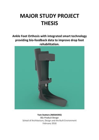
- 57. P a g e | 56 Tom Statters N0564392 Chapter 7- Final Design Solution 7.1- Introduction Following a custom made design process with the inclusion of user feedback loops throughout the initial design and further development stage of the project, a final design solution was determined. 7.2 RecuperGAIT™ - Smart Foot Drop Recovery AFO 7.3- RecuperGAIT™ - Smart Foot Drop Recovery AFO- Design Features 7.3.1- Introduction The RecuperGAIT™ sets a new bench mark for speed and quality of recovery for drop foot sufferers. Combining maximum comfort, bespoke ergonomics and state-of-the-art smart technology providing live bio-feedback to the user. Figure 7.1- Final Design Render (Author)
- 58. P a g e | 57 Tom Statters N0564392 7.3.2- Smart Technology The RecuperGAIT™ utilises smart technology in order to provide live, real-time feedback to the user and their physiotherapist. • Gait pattern- the wearers gait pattern will be assessed using the internal accelerometer. • Pressure mapping- the pressure distribution of the users step will be analysed using internal tactile sensors. • Step counting- the number of steps the user takes will be counted by accelerometer, these can be used to set the user daily tasks or goals, allowing them and their physiotherapist to track their progress. This gait analysis will be sent to a smartphone application via Low Energy Bluetooth. 7.3.4- User Interface The product has been designed to be used in conjunction with a smartphone app that will provide visual and audible cues on improvement that can be made to the user’s gait pattern. Figure 7.2- User app interface • Foot Pressure heat map- a heat map will be displayed on the application showing the
- 59. P a g e | 58 Tom Statters N0564392 Figure 7.3- Render of final AFO Figure 7.4- Side view final render (Author)
- 60. P a g e | 59 Tom Statters N0564392 Figure 7.5- Hinge render (Author) 7.4- PDS Evaluation This final design has met the PDS in the following ways: • It provides Bio-feedback to the patient and physiotherapist to show improvement in the wearer’s gait. • It is within the weight range set in order to ensure a comfortable fit. • It is manufactured in a means that allows for a bespoke and accurate fit. • Main body of product can be recycled. • Defies and solves a clinical need for patients with drop foot.
- 61. P a g e | 60 Tom Statters N0564392 Chapter 8- Conclusion & Further Work This thesis successfully displayed the benefits of a complete user centred design approach, utilising a unique design methodology custom made for this particular project, to improve the time spent in rehabilitation for drop foot sufferers. The final design solution is a result of detailed user research, in both qualitative and quantitative formats. Throughout the project the Nottingham Stroke Association and various drop foot experts provided a wealth of knowledge and potential ideas. A substantial amount of semi-structured interviews were undertaken in order to identify the key themes and aims of the project. Relevant secondary research was carried out into the condition of drop foot in order to create a tailored Product Design Specification (PDS) that solved a clinical need. The user and relevant experts were also involved in the formulation of the PDS. From the PDS, Initial sketches were formulated for 6 potential concepts that provided multiple patient benefits. These were then evaluated using a user and expert weighted Combinex in order to select the most appropriate designs for further development. User feedback and the Combinex provided a clear final design solution that fulfilled the clinical need of reducing time spent in rehabilitation from foot drop. This was achieved by the integration of smart technologies providing bio-feedback to the user. Potential materials and manufacturing processes were analysed and evaluated against each other in order to define the most cost effective method of production. 8.1- Further Work Further work will be carried out on the structural properties of the AFO using Finite Element Analysis (FEA). Physical structural tests on prototype models will also be conducted to assess the comfort and strength of the design. Further design could be done to develop the pressure sensor system in a sock or insole that could be used by individuals who do not suffer from drop foot.
- 62. P a g e | 61 Tom Statters N0564392 References Additive Manufacturing, 2016. 3DP Platform – Transforming Ankle Foot Orthosis (AFO) With 3D Printing [online]. . Available at: http://additivemanufacturing.com/2016/06/15/3dp- platform-transforming-ankle-foot-orthosis-afo-with-3d-printing/ [Accessed 25/01 2018]. Ankle Foot Orthosis [online]. . Available at: https://www.rch.org.au/orthotic/info_for_parents/AnkleFoot_Orthoses_AFOs/ [Accessed 08/01 2018]. Becker Orthopedic, 2018. [online]. . Available at: http://www.beckerorthopedic.com/Featured%20Products/Stance%20Control/TamarackTes t.html [Accessed 08/12 2017]. Bracemasters, 2018. Ankle-Foot Orthosis (AFO) [online]. . Available at: http://bracemasters.com/products/AFO_ankle_foot_orthosis.php [Accessed 02/12 2017]. 'Carlson, J., 1997. Orthotic ankle flexure USA US D385358 S. Patent Application US 29/036,517. 21 Oct. Complete Care Shop, 2018. Reflex Ankle Foot Orthosis - Large - Left [online]. . Available at: https://www.completecareshop.co.uk/orthopaedic-aids/ankle-foot-orthoses/reflex-ankle- foot-orthosis-large-left [Accessed 01/12 2017]. Design Council, Double Diamond [online]. . Available at: https://www.designcouncil.org.uk/news-opinion/design-process-what-double-diamond [Accessed 02/11 2017]. DFRobot CurieNano – Anano Genuino/Arduino 101 Board,2017. [online]. . Available at: https://digitalmeans.co.uk/shop/dfrobot_curienano-a_nano_genuino_arduino_101_board [Accessed 22/01 2018]. Difference Between, 2016. Difference Between Gyroscope and Accelerometer [online]. . Available at: http://www.differencebetween.net/technology/difference-between- gyroscope-and-accelerometer/ [Accessed 09/01 2018]. FDA, 2011. Product Classification [online]. . Available at: https://www.accessdata.fda.gov/scripts/cdrh/cfdocs/cfpcd/classification.cfm?ID=5118 [Accessed 11/12 2017]. Gait Cycle, 2017. [online]. . Available at: https://www.streifeneder.com/downloads/o.p./400w43_e_poster_gangphasen_druck.pdf [Accessed 15/01 2018]. Garmaon Health, 2003. Pronation and Supination [online]. . Available at: http://www.garmaonhealth.com/run-pain-free/ [Accessed 26/01 2018].
- 63. P a g e | 62 Tom Statters N0564392 Gov.uk, 2014. Medical devices: legal requirements for specific medical products [online]. Gov.uk. Available at: https://www.gov.uk/government/publications/medical-devices-legal- requirements-for-specific-medical-devices/medical-devices-legal-requirements-for-specific- medical-devices [Accessed 14/01 2018]. Granta, CES Selector. 2017th ed. Health & Care, 2018. Leaf Spring Foot Drop Ankle Support. http://www.healthandcare.co.uk/foot-drop-supports-and-afo/fixed-foot-drop-ankle-and- foot-support1.html ed. 'Hoyle, B.'., 2005. Foot Drop [online]. . Available at: http://www.encyclopedia.com/medicine/diseases-and-conditions/pathology/foot-drop. Last accessed 12/12/17. [Accessed 12/12 2017]. Kerkar, P., 2015. Foot Drop: Symptoms, Treatment, Exercises, Recovery [online]. . Available at: https://www.epainassist.com/sports-injuries/foot-and-heel-injuries/foot-drop [Accessed 24/11 2017]. 'Mullins, C., 2016. Pilates strategies for foot drop [online]. . Available at: https://www.bodyorganics.com.au/pilates-strategies-foot-drop/ [Accessed 06/01 2018]. National Careers Service, 2017. CNC machinist [online]. . Available at: https://nationalcareersservice.direct.gov.uk/job-profiles/cnc-machinist [Accessed 05/02 2018]. NHS, 2016. Working in the NHS [online]. . Available at: https://www.jobs.nhs.uk/about_nhs.html [Accessed 05/02 2018]. 'Pheasant, S., 2005. Bodyspace: Anthropometry, Ergonomics and the Design of Work. Third ed. CRC Press. 'Pritchett, J., 2016. Foot Drop [online]. . Available at: https://emedicine.medscape.com/article/1234607-overview [Accessed 11/11 2017]. Prosthetist/Orthotist2016. [online]. . Available at: https://www.inputyouth.co.uk/jobguides/job-prosthetist-orthotist.html [Accessed 05/02 2017]. 'Pugh, S., 1990. Total Design: Integrated Methods for Successful Product Engineering. 01st ed. Prentice Hall. 'Retina, M., 2016. Foot Drop [online]. . Available at: https://www.webmd.com/a-to-z- guides/foot-drop-causes-symptoms-treatments [Accessed 12/15 17].
- 64. P a g e | 63 Tom Statters N0564392 SingleTact Standard Sensors,2018. [online]. . Available at: https://www.singletact.com/micro-force-sensor/ [Accessed 01/14 2018]. SingleTact, 2016. QUICK START GUIDE [online]. . Available at: https://www.singletact.com/QuickStart.pdf [Accessed 14/01 2018]. 'Smith, C.O., J.', 2010. Apparatus for providing dorsiflexion assistance in ankle foot orthoses and night splints USA US 7678067 B1. Patent Application US 11/784,858. 16 Mar. Stroke Association, 2013. Stroke Statistics [online]. . Available at: http://www.thepossibilities.co.uk/assets/downloads/stroke-statistics.pdf. [Accessed 16/12 2016]. 'Stroke Association', 2015. Stroke Statistic [online]. . Available at: https://www.stroke.org.uk/sites/default/files/stroke_statistics_2015.pdf. [Accessed 02/11 2017]. Stroke Focus, 2017. Exercises for Drop Foot [online]. . Available at: https://www.strokefocus.net/blogs/view/23/exercises-for-foot-drop [Accessed 23/11 2017]. Study Blue, 2014. Compensating for footdrop [online]. . Available at: https://www.studyblue.com/notes/note/n/an1-11-pic-leg-and-ankle-joint/deck/8940825 [Accessed 11/11 2017]. SingleTact Standard Sensors2018. [online]. . Available at: https://www.singletact.com/micro-force-sensor/ [Accessed 01/14 2018]. TinyTILE - Intel Curie Dev Board 2018. [online]. . Available at: https://coolcomponents.co.uk/products/tinytile-intelr-curie-dev-board [Accessed 23/01 2018]. TechMed, 2018. 3D Body Scanner [online]. . Available at: https://techmed3d.com/products/bodyscan-scanner/ [Accessed 01/05 2018]. 'Wiggin, M . Westbrook, A. Sawicki, G. Willson, A. Rahhal,T. Barnette, W. Lasater, K.', Nov 7, 2013. Ankle-foot orthotic devices with integrated vibrotactile biofeedback and related methods. USA US 20130296741 A1. Patent Application US 13/886,247.