SlideShare a Scribd company logo
1 of 78
Download to read offline
Durham E-Theses
Acoustics of the orchestral kettledrum
Packer, Thomas Arnold
How to cite:
Packer, Thomas Arnold (1993) Acoustics of the orchestral kettledrum, Durham theses, Durham University.
Available at Durham E-Theses Online: http://etheses.dur.ac.uk/5633/
Use policy
The full-text may be used and/or reproduced, and given to third parties in any format or medium, without prior permission or
charge, for personal research or study, educational, or not-for-prot purposes provided that:
• a full bibliographic reference is made to the original source
• a link is made to the metadata record in Durham E-Theses
• the full-text is not changed in any way
The full-text must not be sold in any format or medium without the formal permission of the copyright holders.
Please consult the full Durham E-Theses policy for further details.
Academic Support Oce, Durham University, University Oce, Old Elvet, Durham DH1 3HP
e-mail: e-theses.admin@dur.ac.uk Tel: +44 0191 334 6107
http://etheses.dur.ac.uk
Acoustics of the Orchestral Kettledrum. MSc Thesis, T A Packer
A B S T R A C T
A complete theoretical overview of the acoustics of the kettledrum is taken.
Starting with the well understood vibrations of a stretched circular membrane in a
vacuum, the thesis goes on to investigate the deformation produced when the drum
is struck and the subsequent behaviour of the system with time. The vibration of
the membrane is modified by mass loading, by the hemispherical kettle, by the
membrane's stiffness and by the air loading present; the latter is accounted for
using a Green function technique. These effects produce significant changes to the
frequencies of a freely vibrating system. The results are compared with those
obtained experimentally, with good agreement. The most significant conclusions
are that the air loading modifies the frequencies of vibration of those modes having
only radial nodes to match the harmonic series, thereby creating a distinct
sensation of musical pitch, and that the fundamental mode of vibration is damped
completely.
ACOUSTICS OF THE ORCHESTRAL KETTLEDRUM
Thomas Arnold Packer
Master of Science Thesis, University of Durham
1993
The copyright of this thesis rests with the author.
No quotation from it should be published without
his prior written consent and information derived
from it should be acknowledged.
JAN 1994
3 -
CONTENTS
Abstract
Contents
Tables and Diagrams
Introduction
Section 1: Vibrations of a stretched membrane in a vacuum
1.1 Derivation of the wave equation for a stretched
membrane and the normal modes of vibration
1.2 Determination of the form and frequency of the
normal modes
Section 2: Deformation of a membrane under a drumstick
2.1 The displacement at any position on the surface
of a membrane due to a deformation at a specified
position using the method of images
2.2 Deformation of a membrane under an impulsive
force
Section 3: Consideration of the effects of the cavity upon the
modes of vibration
3.1 Membrane coupled to a Helmholtz Cavity
3.2 Membrane coupled to a closed cavity
3.3 Effect of the size of the cavity
3.4 The effect of the kettle as a baffle
3.5 General considerations
Section 4: Air loading
4.1 Modelling air loading using Green's Functions
4.2 Determination of the normal modes
Section 5: Other considerations
5.1 Mass loading
5.2 Membrane stiffness
Section 6: Radiation effects and the time development of the system
6.1 Radiation effects
6.2 Time development
5
8
11
11
16
19
19
23
24
24
28
33
34
34
37
37
44
49
49
51
53
53
56
- 4
Section 7:
Conclusions
Appendix A:
Appendix B:
Appendix C:
References
Observations
7.1 Pitch
7.2 The observed sound of the kettledrum
7.3 Experimental results
Properties of Bessel Functions
Polyethene Terephthalate
Green's Functions
58
58
60
61
64
68
73
74
75
TABLES A N D DIAGRAMS
Figure I . l Range of the orchestral kettledrum
Figure 1.1 Element dS under tension T
Figure 1.2 Shapes of some of the normal modes
Figure 2.1 A membrane of radius a struck with a force
at a distance b from the centre
Figure 2.2 Usual form of a kettle drum stick
Figure 3.1 Cross section of a kettledrum
Table 3.1 Frequency modification due to a Helmholtz cavity
Table 3.2 Frequency modification due to a closed cavity
Figure 3.2 Normal modes for three different air volumes
Table 4.1 The calculated effect of air loading on the
normal mode frequencies
Table 6.1 Calculated decay times of the normal modes
Figure 7.1 The harmonic series
Figure 7.2 Observed sound spectra of the kettledrum
Table 7.1 Observed frequencies of the normal modes
Table 7.2 Observed time decays of the normal modes
12
18
19
22
24
32
32
33
47
57
58
61-62
63
63
D E C L A R A T I O N
None of the material contained in this Thesis has been submitted for any degree in
this nor any other University.
The Copyright of this Thesis rests with the author. No quotation from it should
be published without his prior written consent and information derived from it
should be acknowledged.
T A Packer April 1993
- 7 -
To
Janet
without whose support
this thesis would have not been possible
Introduction
This Thesis is concerned with the acoustical properties of the orchestral
kettledrum. The usual kettledrum, often referred to by its Italian name
timpano (plural timpani) in musical scores, consists of a hemispherical bowl of
fibreglass or copper over whose open part a membrane is stretched, normally of
calfskin or a plastic ^ material. By means of screw attachments or a foot pedal
mechanism the tension of this membrane can be altered. The drums are available
in several standard sizes, the most common being a pair of diameters seventy—one
centimetres and sixty-four centimetres (28 and 25 in). Others are used in more
ambitious scores with diameters of seventy-six, sixty-six and fifty-eight
centimetres (30, 26 and 23 in) to supplement this usual pair. Sadie (1984) gives
more details of the construction of these instruments.
On striking the drum, off centre, at about a quarter of the way between the rim
and the centre, with a suitable stick, often haying a soft, felt covered head, the
instrument produces a musical note of identifiable pitch, the actual pitch
depending on the size of the drum and the tension of the membrane, enabling the
drums to contribute to the orchestral colour and harmony. The range of the usual
pair is shown in figure I . l .
large drum (71cm) small drum (64cm)
- j-^
o
87 Hz 131 Hz 117 Hz 174 Hz
Figure I . l Range of the orchestral kettledrums
Mylar or I C I Melinex (Polyethene Terephthalate): see Appendix B.
The musical role, history and performing techniques of these instruments are
adequately covered by Blades (1973a and 1975).
At the bottom of the hemispherical shell there is a small hole (of radius
approximately one centimetre) to equalize the pressure inside and outside of the
drum in the event of a change in atmospheric conditions. It is suspected by some
authors that this produces a significant effect on the sound produced (eg Benade
1976a) whilst other maintain that it has little or no effect (eg Rossing 1982a).
However it is apparent that the cavity itself, as well as contributing to the
aesthetic appearance of the drum, affects the sound produced.
This thesis attempts to explain how the membrane will behave when struck and to
investigate the effects of air damping, the bowl and the hole mentioned above to
give a theoretical sound spectrum. Comparison with the harmonic series may then
give an insight into the tone colour to be expected and to estabfish the nominal
pitch of the drum, often the source of debate amongst musicians, eg Berfioz (1844).
Rayleigh (1945a) produced expressions for the behaviour of a stretched membrane;
much of his theory still stands and has been utifised here. Certain misconceptions
on his part led to an error in his treatment of a mass loaded membrane (Rayleigh
1945b) and this has been perpetuated by others (eg Morse 1948a). The correct
treatment has been suggested by Kornhauser and Mintzer (1953a). Benade
(1976b) has produced tables of frequencies based on experimental results, although
he does not give any procedural details. More recent research by Christian et al
(1984a), which concentrates especially on the problems associated with air
damping, also gives tables of frequencies, based on both practical observations and
theoretical calculations. Rossing (1982b) and Fletcher and Rossing (1991a) have
produced tables showing the effect of the size of the bowl of the instrument.
- 10
In short, the mathematical treatment of the vibrations of a stretched membrane in
a vacuum is well understood; the more specialised problems encountered with
kettledrums are not so well documented. This thesis is intended to address these
problems and to bring together the work of other authors on the subject.
Section 1 deals with the vibration of a stretched membrane not subject to any
restrictions or damping forces. Section 2 introduces a suggested function to define
the initial displacement that the membrane might suffer when struck with a
typical drumstick.
Section 3 takes into account the effects of the cavity, assuming some kind of
average displacement of the membrane; various treatments of this cavity problem
are advanced, each with its own assumptions and conditions. Section 4 deals with
the air damping of the system. In Section 5, consideration is given to other
effects: the mass loading effect of the drum stick and the stiffness of the
membrane. Section 6 deals with the time development of the system and
radiation effects.
The whole thesis should be read bearing in mind the discussion of Section 7 which
is based on observations made by performers and comments on the sensations of
pitch, together with experimental results showing the frequencies of the important
modes of vibration.
Section 1
11 -
Vibration of a stretched membrane in a vacuum
This section deals with the modes of vibration of a simple, circular membrane, not
subject to any restraining forces and firmly fixed around its perimeter.
1.1 Derivation of the wave equation for a stretched membrane and of the
normal modes of vibration^.
Although polar co-ordinates will be used to specify points on the membrane's
surface later, the initial wave equation is simpler to derive using cartesian
co-ordinates, in which the displacement y is expressed as
y = y(x, z, t) where x, z defines a point on the surface
and t defines the instant in time.
The membrane will be assumed to have negfigible stiffness, to be perfectly elastic,
to be of uniform thickness and to be subject to small displacements. I f o is the
area density (in kg m'2) and T the tension (in N mi) to which the membrane is
stretched at its edge, then the net force acting on the element dS { - dx.dz) due
to the tension along the sides dz is
Tdz
x+dx
which reduces to
52y
dxdz
2 Similar calculations are to be found in Raleigh (1945a) and Kinsler and Frey
(1962a).
12
and that due to the tension acting along dx is
52
5i
dxdz
(refer to fig 1.1)
(The tension will be distributed uniformly throughout the membrane, so that the
material on opposite sides of a line segment dl will be pulled apart with a force
T.dl Newtons).
Tdx
Figure 1.1 Element dS under tension T
This restoring force will equal the product of mass and acceleration, the mass
d^v
being a dx dz and acceleration Hence
dx dz = o dx dz
or
d2y
dt^
= r2
(1.1)
(1.2)
13
where T
a
(1.3)
c in fact being the speed of propagation of transverse waves in the material.
Polar co-ordinates may be used with advantage when deafing with this circular
membrane. Equation (1.2) may be expressed more generally as
(1.4)
In the case of the circular membrane having a fixed boundary of radius a, it is
necessary to express in terms of the polar co-ordinates, r and 9, where
X = r Cos^ and z = r Sin^. By partial differentiation with respect to r and 0,
the operator is found to be:
y2 - 52 1 5 , 1 52
(1.5)=
Substitution into (1.4) gives
dF - ^ ^ + F ^ + F^
1 52
(1.6)
The boundary condition imposed on this equation is that the displacement must be
zero at the circumference, ie y = 0 when r = a.
Assuming that y is a harmonic function of time (ie y is proportional to Cos
{ut — e)) and writing ^ as k
(17)
^ Similar calculations are to be found in Raleigh (1945a) and Kinsler and Frey
(1962a).
1 4 -
Whatever y's relationship with r and 0 it can be expressed as a Fourier series
y = yo + y i Cos {0 + ei) + y2 Cos2 [0 + 62). (1.8)
in which yo, y i , etc are functions of r but not 0.
Substitution of (1.8) into (1.7) gives:
Yn Cos n{0+ en) = 0 (1.9)
for all integral n  0 .
Multiplying both sides by Cosn((?+ en) and integrating with respect to 0
between fimits of 0 and 2ir, each term must vanish separately, and thus it is
possible to determine y n as a function of r.
d ! y n , I d v n , [ k 2 - ^ ^ yn = 0 (1.10)^
The solution of (1-10) involves two distinct functions of r each multipfied by an
arbitrary constant. One of these functions becomes infinite when r becomes
zero, and hence the corresponding particular function may be excluded as it does
not satisfy the prescribed conditions^.
The other solution satisfying (1.10) is Bessel's function of order n (denoted by
Jn(kr)) and may be expressed in several ways^
^ I t makes no difference whether Cos n (^ + fn) is included in yn or not.
^ Rayleigh (1945c) gives examples of this situation.
^ The properties of Bessel Functions are appended to this thesis, Appendix A.
- 15
In accordance with the usual notation for Bessel functions the expression for the
vibration of a normal component may be written as:
y = PJn(kr)Cos n(?+e)Cos (wt + 7) (1.11)
the boundary condition requiring that
Jn(ka) = 0 . (1.12)
The complete solution for y is obtained by combining all the possible solutions
embodied in (1.11) with all permissible values of n and k. As a function of r
and 9, y can be expressed within the fimits of the circle radius a in the series
y = ^ ^Jn(kn,ir)^^n,iCos n^? (1.13)
1 n
where (kn,ia) is the i'^zero of Jn(kn,ia)
n = 1, 2, 3 etc.
For every integral value of n there is a series of values for k given by (1-12) and
for each of them (pn,i is arbitrary. The estabfishment of these constants can be
achieved in the following manner. The energy of the motion is equal to
 p ( f y2rdrd?
where p is the density of the membrane
and when expressed by means of normal co-ordinates it can only involve their
squares, it follows that the product of any two terms in (1.13) becomes zero when
integrated over the area of the membrane. Multiplying both sides of (1.13) by
Jn(kn,ir)Cos(n^?)r and integrating
16
/.a /,27r a 27r 2
/ / yJn(kn,ir)Cos(n^?)rdrd?= / / ?in,irJi.(kn,irl Cos2(n?)rdrd^
•^0 -^0 -^0 -^0 L . J
(1.14)
the right—hand side reduces to
a 2
7r?in,i / rJn(kn,ir)l rdr (1.15)
•^0 L J
j
- 2 ^2 2
J n ( k n , i r ) l rdr is found to be^ f J +.(kn,ia)l . Hence the
n L J ^ L J
2
| J n ( k n , i r ) | rdr is found to be? ^ | Jn,i(kn,ia) |
'0
values of the coefficients (pn,i (n = 1, 2, 3 ... i = 1, 2, 3 ..) can be determined
from
J f yJn(kn,ir)Cos(n/?)rdrd^
0n,i = • (1.16)
7ra2
2~ J n n ( k n ' i a )
The displacement of a membrane, then, can be expressed as the sum of a set of
normal modes, whose ampHtudes are easily determined.
1.2 Determination of the form and frequency of the normal modes^
Consideration of equation (1.11), rewritten here for a specific mode, (n, i) shows
the character of each mode.
yn,i = ^n,iJn(kn,ir)Cosn?Cos wt . ( l . 17)=(l. 11)
See Appendix A
8 Similar calculations, extending to annular membranes are to be found in
Gray and Matthews (1895a)
- 17
Each element of the membrane will exhibit simple harmonic motion of period — .
The frequency of oscillation is therefore
•' 2n 27r 27r
r r
a '
The amplitude of this element is
(1.18)
see (1.3)  (1.7).
A = (^n,iJn(kn,ir)Cos n^ (1.19)
which vanishes, and the element accordingly remains at rest if
or i f
Jn(kn,ir) = 0
CosnO = 0
(1.19a)
(1.19b)
The first is satisfied not only at r = a but also when
r = r = r
'^n ' ( i-i) ^
kn,i
(1.20a)
Consequently there is a series of (i - 1) nodal circles, concentric with the fixed
boundary.
The second equation (1.19b) is satisfied when
6 =
2n
(4n-l)7r
- 2ir^
(1.20b)
giving rise to n nodal diameters, dividing the membrane into 2n equal sectors,
18 -
all vibrating in precisely the same way, alternate sectors moving in opposite
directions. Figure (1.2) gives a representation of the motion experienced by such
membrane. (Some excellent photographs, showing some of the normal modes,
obtained by sprinkling sand on to a timpano are appended to Rossing (1982a)).
(0.1)
( 1 . 1 ) — .
(1.2) —
(0.2)
(0.3)
(2.1)
Figure 1.2. Shapes of some of the normal modes of
vibration of a circular membrane (Arrows point to the nodal lines)
Having ascertained that the displacement of a membrane can be expressed in
terms of its modes, it has been shown that it is then possible to determine the
natural frequency of each of these modes and their associated shapes. The relative
amplitudes of the modes will depend on the initial displacement of the membrane,
dealt with i n Section 2.
19
Section 2 Deformation of a membrane under a drumstick
This section deals with the shape of deformation caused by striking the drum at a
point other than its centre.
2.1 The displacement at any point on the surface of a membrane due to a
deformation at a specified position using the method of images.
Figure 2.1 A membrane of radius a struck with
a force at a distance b from the centre
For an infinite membrane, the pressure, P(r), is given by:
TV2'^(r) = - P ( r ) (2.1)
where V'(r) is the displacement
at r due to P(r).
For a point force F at b:
TV2'^(r) = - F ( 5 ( r - b ) (2.2)
2 0 -
the solution of which gives as
= 2 ¥ J ^ H ^ - ^ ) (2.3)
where T is the tension of the
membrane as defined in Section 1.1.
For a finite membrane, the method of images can be used to obtain an expression
for the displacement, ip, in terms of the initial force, —F. ' The method follows
the usual pattern employed in electrostatics problems of this nature (Bleaney and
Bleaney (1989)). The method of images enables the boundary condition at the
perimeter to be met; an image force +F is introduced outside the membrane at a
distance c from the centre to yield zero displacement at the edge. Figure 2.1
shows this situation.
The displacement due to a point force - F evaluated at the boundary point P is
i)_ = In(a2 + b2 - 2ba Cos 0)^ + A_ (2.4)
and that due to +F at P is
= ^l^j^ ln(a2 + c2 - 2ac Cos f)^ + A_j_ (2.5)
where A_ and are arbitrary
constants.
The net displacement is therefore
ijj= tjj_^ + 2 ^ In
a2 + b2 - 2ab Cos 0
a2 + c2 - 2ac Cos (J
+ A _ + A ^ . (2.6)
21 -
The requirement is that P, being situated on the boundary, must have zero
displacement. To achieve this, the ratio
a2 -f b2 - 2ab Cos 0
a2 + c 2 - 2 a c Cos 0
must be independent of 0; that is to say
a2 + b 2 - 2 a b Cos 0 _ /o
a 2 + c 2 - 2 a c Cos 0  ^ ^^•^)
where k ' is a constant.
Rearranging equation (2.7),
a2 + b2 - 2ab Cos 0 = k'(a2 + c2) - 2k'ac Cos 0 (2.8)
or
a2 + b2 - k'(a2 + c2) + (2k'ac - 2ab)Cos 0=0 (2.9)
for which the coefficient of Cos 0 must itself be zero, i.e.
k' = ^ (2.10)
then since
it follows that
hence
a2 + b 2 - k ' ( a 2 + c2) = 0 (2.9a)
a2 = cb (2.11)
k ' = 1^ (2.12)
22
the displacement, ip at the boundary therefore follows as
^ = 2 i T
In
a
+ A_|_ + A (2.13)
-F b
and choosing A . + A as 75-^^ In - gives zero at the boundary. The general
displacement at a point (r, 0) will be
In
r2 + b 2 - 2 b r Cos 6
r 2 + c 2 - 2 r c C o s 0
1
a
(2.14)
with c
h
It has been intimated by Morse (1948b) and Kornhauser and Mintzer (1953b) that
a point force or one whose radius of contact is  F/2 ttT, would cause the
membrane to break. Thus the expression obtained above is only valid if the force
is taken over a finite area. Fortunately this is exactly what happens when the
skin is struck with a typical drumstick. The shape of a common stick is shown in
figure (2.2)
Figure 2.2 Usual form of a kettledrumstick
The displacement given in equation 2.14 is hence invafid for a point within the
area of contact; the displacement for such a point will be equal to the initial
displacement caused by the stick's blow. Outside the area of contact the
displacement is given by (2.14); a discontinuity is introduced at the edge of the
area of contact.
23
2.2 Deformation of a membrane deriving from an impulsive force
In the foregoing description of Section 2.1 it has been assumed that the membrane
is released from a static position, from which it is released to perform the
vibrations described in Section 1. The case of the stick producing an impulse
rather than this static deformation will not be considered for intuitive reasons; the
mass of a stick is considerably greater than the mass of a typical membrane
(which, after all, has been taken as massless in the treatment of Section 1) and
practical experience of playing these instruments which shows that the skin
produces a definite upward force to the drumstick, which assists playing technique.
This effect will give rise to a mass—loading of the membrane for its first half cycle.
(Section 5).
24
Section 3. Considerations of the effect of the cavity upon the
modes of vibration
This Section attempts to suggest ways in which the cavity behind the membrane
in a real situation may adapt the behaviour of the drum.
3.1 Membrane coupled to a Helmholtz cavity.
Treating the kettle as a Helmholtz resonator, and examining the coupling between
the membrane and this cavity produces expressions to amend the natural
frequencies of Section 1. Damping can also be introduced; damping may occur
due to the energy losses associated with the movement of air through the small
hole at the bottom. Figure 3.1 shows such an arrangement. Opinions differ as to
the importance of this hole in the overall sound spectrum (Benade (1976a),
Rossing (1982a))
area A
effective length 1'
radius b
Figure 3.1 Cross Section of a kettledrum
The membrane's movement is denoted by y, and that of the air through the hole
by x.
Rayleigh (1945d) gives the expression for the effective length of the air plug of a
Helmholtz resonator in the case of a small circular aperture in a thin wall as
- 2 5
r
A
2 ¥
( 3 . 1 )
where A is the area of cross section of the hole,
b is its radius,
1' is the effective length.
Helmholtz (1912) and Wood (1953) give details of the principles involved in the
resonance of such a cavity, such as the one under consideration here. The
equation of motion of the air plug is
^ . w d2x , A n dx c2A
Ax - J* ^ ds (3.2)
where pa = density of air
X = displacement of air plug
= displacement of membrane
D = damping constant
c = velocity of sound in air.
The flow of air through the hole is damped by viscous forces acting at the opening;
dx
these are accounted for by the D ^ term in (3.2).
Defining an average displacement, y for the membrane of radius a
y = ^ / ^ d s (3.3)
and from (3.3) and (3.2)
d2x , p. dx , c2Ax c2 ,
(3.4)
the equation of motion of the membrane is
-26
P n , h ^ Ax - J Tp ds (3.5)
where h = thickness of membrane
Pni = density of membrane
ip can be expressed as the sum of the normal modes of the membrane (Section 1)
= Y J ^^^^
(3.6)
where (pi is a mode
ai is the ampfitude.
As an approximation
J ipds = ^ a-i J ' (pids - M j $!'ods (3.7)
The last approximation deriving from the fact that the fundamental is the
only mode without nodes, (apart from the perimeter) hence only is coupled to
the resonator in this approximation. By considering the fundamental alone, and
averaging the equation of motion over the area of the membrane gives:
,,2 , PaC^ , 7ra' P-A c2Ax
/9,n V h
(3.8)
where u)m — frequency of fundamental.
The resonant frequency of the cavity, according to Helmholtz (1912) and Wood
(1953) is
- ^2 (3.9)
- 2 7 -
Two constants, a and P are defined, such that
a
7ra^
AT
and P ^ ^
using these in (3.4) and (3.8) and trying solutions of the form x = xoei'^^'',
y = yoe^^*^ the following identities are obtained:
CJ^XQ + iwDxo + WcXo = aulyo (3.10)
w2yo + (wm + apojl)yo = Puho (3.11)
For this solution to be non-trivial, the value of the determinant
Lj^ — i wD — Lol
Pul
u/ -{UJI + aPul)
must equal zero, i.e.
[iJ - iwD - UI){LJ^ - [ul + aPul)) - aPuf: - 0 . (3.12)
Its solution leads to the two normal mode frequencies.
For the lossless case (D = 0) an examination of equation (3.12) shows that one
normal mode frequency will be greater than the larger of Wc and J ul + aPcol,
whilst the other will be less than the smaller of these.
- 2 8
The frequency of the fundamental will therefore be altered by a factor of
1 + if the damping factor is taken as zero. (The resonant frequency of
the cavity is found to be about 25Hz.)
The justification for considering only the fundamental in the approximation of
(3.7) was that any one of the modes with nodes will not produce a comparable
volume change. Certainly all modes having diametrical nodes will produce no
volume change whatsoever. This gives rise to the fact that the fundamental is not
only the most seriously affected by the cavity in terms of a change in natural
frequency, but must also be the most seriously affected by the damping effect of
the air moving through the small hole.
3.2 Membrane coupled with a closed cavity.
In this treatment the kettle is considered as being an airtight cavity. This
approximation will be better for the higher modes that involve a volume change
that is small compared to the volume of the cavity.
If the speed of transverse waves in the membrane is considerably less than the
speed of sound in air, then the compression and expansion of the enclosed air will
be more or less the same over the whole extent of the membrane, and will depend
on the average displacement of the membrane.
When the membrane is displaced from equifibrium to a shape determined by V)
the volume of the vessel is diminished by
29
- a 27r
A V = j j ilKdidO . ( 3 . 1 3 )
' 0  0
If the equifibrium volume is VQ and density po then when the alternations of
pressure within the vessel are large enough to be adiabatic, the excess pressure
inside the vessel will be
r 2-1 . a 27r
P = - ^ C f ^dvdO (3.14)
where Ca is the speed of
sound in air.
(The minus sign originates from the fact that the pressure is in the opposite
direction to the displacement of the membrane.)
The equation of motion of the membrane is, therefore
2 T . a ^27r
f f M^dO ( 3 . 1 5 )
V o l J ^0 -^0
where c is the speed of
transverse waves in the
membrane.
For simple harmonic vibrations
ip = Y(r, ^)e-i^t
V2Y + ^ Y =
2 2 T . a 27r
f f YvdxdO . (3.16)
V o l J ^0
30
If Y = Sin (n^?)Jn( — ), n  0, the integral on the right-hand side will be zero
(owing to the integration over 0), and the solution that satisfies the boundary
conditions Y = 0 at r = a will be the solutions derived in Section 1, with the
corresponding allowed frequencies. The presence of the airtight cavity does not,
then, according to this treatment, appear to affect the normal modes having one or
more diametrical nodes (i.e. n  0).
If n is zero then the integral on the right-hand side of (3.16) is not zero. The
solution without the integral is Jo( ^ ) so trying the solution
Y = Jo( ^ ) — Jo( ^ ) which satisfies the boundary condition, the integral
reduces to
wa
f Yrdrd0=
'0 O
c
wa c~ Jo C
(3.17)
where x = Mch'/V^T)
substituting this into equation (3.16) and using the properties of Bessel functions,
(see Appendix A ) , gives:
T - ^
-r fbJSis 2c f /waJ _ -X T /was
(3.18)
This equation determines the allowed values of the frequency for those normal
modes that are independent of 0 (i.e. having no nodal diameters).
The constant x is a. measure of the relative importance of the cavity with respect
to the tension, as a restoring force on the membrane. The limiting case x = 0 is
- 3 1
the one studied in Section 1. Morse (1948c) gives a table showing how the
frequency varies with x- The presence of the vessel tends to raise the frequencies.
Sen (1990) has produced a similar expression for allowed frequencies; his result is
identical to that of Morse (1948c).
Morse (1948d) gives an approximate formula for the frequency, vafid for small
values of x as
f - - fo 1 +
Poc|T
(3.19)
where fo is the frequency
when X is 0
a is the area density
of the membrane.
Kinsler  Frey (1962a) in a similar treatment of this problem define a constant
ra 7
a = (3.20)
• where PQ is initial pressure
7 is ratio of heat
capacities of air
which is again an expression for the importance of the cavity.
A similar expression is arrived at for u
Jo
wa
~c
( wa ^
- a J , ^ ^ 2 (3.21)
from which it is evident that x and a are equivalent.
Table 3.1 shows the frequency modification factors for various values of x and
different modes, derived from (3.19).
32 -
X Frequency modification
0 1.0
0.5 1.041 86
1 1.082 11
2 1.158 40
3 1.229 97
4 1.297 60
5 1.361 87
6 1.423 25
8 1.538 68
10 1.646 03
Table 3.1 Frequency modification due
to a Helmholtz cavity
Frequency modification
X (0,1) (0,2) (0,3) (0,4)
0 1.0 1.0 1.0 1.0
0.5 1.029 39 1.001 080 1.000 145 2 1.000 026 6
1 1.037 74 1.002 220 1.000 326 7 1.000 079 9
2 1.111 69 1.004 553 1.000 726 1 1.000 186 5
3 1.162 51 1.007 000 1.001 089 1 1.000 293 1
4 1.210 32 1.009 561 1.001 488 4 1.000 399 6
5 1.254 60 1.012 293 1.001 887 1 1.000 506 2
6 1.295 10 1.015 139 1.002 287 1 1.000 612 8
8 1.364 67 1.021 285 1.003 122 1 1.000 825 9
10 1.450 16 1.028 115 1.004 029 5 1.001 103 9
Table 3.2 Frequency modification due
to a closed cavity
- 3 3
3.3 The effect of the size of the cavity.
Experimental evidence shows that reducing the size of the cavity produces
significant effects on the frequencies of each of the modes. Rossing (1982c) shows
that reducing the volume of the cavity by a quarter produces little effect, whilst
reducing the volume to a half, and then to only one—quarter of its original size
produces a dramatic shift in frequency. The volume was altered by part filling
the drum's cavity with water. Christian et al (1984a) give measured results which
are reproduced in Section 7, together with a tentative theory as to the importance
of the cavity volume^. Figure 3.2 shows the effect of altering the volume for some
of the modes. (From Fletcher and Rossing (1991b).)
337 Hz 385 Hz 537 Hz 655 Hz 566 Hz 747 Hz 816 Hz
i
2
S t
313 Hz 771 Hz 515 Hz 644 Hz 705 Hz
(322 Hz)
J ^
518 Hz 642 Hz 706 Hz
Figure 3.2 Normal modes for three different air volumes
9 See Section 4.2.
34
3.4 The effect of the kettle as a baffle.
The fact that the kettle only exists on one side of the membrane effectively
prevents any sound from being radiated from the underside of the membrane.
The (0, 1) mode will therefore act as monopole source, radiating sound waves
outwards in a hemispherical manner from the upper surface of the drum. Without
the kettle, it would, of course act a dipole source. The other modes, however will
act as multipole sources; the ( 1 , 1) mode for example will be a dipole source, the
(2, 1) mode a quadropole source. This action of the kettle has several
implications. In the first place, the sound radiated from the underside of a
membrane without the kettle as a baffle will be exactly half a cycle out of phase
with that radiating from the top, thereby causing interference, and the sound
would not be as efficiently radiated in the plane of the membrane. As it is, the
kettle effectively cuts off the sound from the underside, thereby leaving the sound
from the upper side to radiate well. Another acoustical characteristic is that
sound from a monople source radiates with great efficiency, which implies that the
vibration giving rise to this monopole source will die away much more quickly
than that from dipoles or quadropoles. This suggests that the fundamental (0, 1)
mode will not have a long time duration.
3.5 General considerations.
The fundamental frequency of the membrane from Section 1 is
2-404
'^in = — r — y (3.22)
(2-404 is the first zero of Jo)
hence
- 3 5
1 ^ l(0-777r)'
(3.23)
The parameter x has been defined as
and so
X
7rp 0 c ^ a*
VoT
(3.24)
X
•Kpoch^ _ 2-404^
(3.25)
X =
po c^Tra^ _ 2-404^
/5m Voh 2
(3.26)
/)ni is density of membrane ( = )
;^ = 2-404 V
X = 5 - 8 5 a ; 0 ^
(3.27)
(3.28)
a and ^ are defined in Section 3.1.
The theory of Section 3.1 gives the frequency as
/• _ Win
^ - 2^
(3.29)
in the closed cavity limit.
The frequency in this case has modified the cavity-less value by a factor of
or 1 + X5-85
Comparison of this with the results of
36 -
Section 3.2 shows reasonable agreement at least for the lower values of x -
Table 3.1 shows the modification to the frequency according to the theory of
Section 3.1; it should be compared with the results shown in Table 3.2.
Other coupfing effects will be experienced by the system; the higher frequencies of
the drum will couple with the spherical modes of the cavity. These modes can be
expressed by means of spherical Bessel functions, but the relatively low amplitude
of most of the affected modes does not render a full treatment worthwhile at this
stage.
It has been shown in this section that the frequencies of all modes that have no
nodal diameters are affected by the cavity. A constant x has been defined,
giving the relative importance of the cavity to the system. In all cases for which
X  0 the cavity has the effect of raising the frequencies of these modes. In
addition there is a damping factor due to the viscous effect of the air being forced
through the small hole at the bottom of the cavity by the vibrating membrane.
This factor again only affects the modes with no diametrical nodes, reducing their
amplitude; it is suspected that since this effect must depend on the volume of air
the membrane displaces that this damping will be far more apparent on the
fundamental than on any other modes. By far the greatest effect of the cavity,
however, is as a baffle, causing the fundamental (0, 1) mode to be a monopole
sound source, and therefore die away quickly. However, air damping, (Section 4)
can be shown to have a far greater impact on the frequencies of the modes of
vibration, as well as affecting their amplitudes and decay times.
- 3 7
Section 4. Air Loading
This section deals with the modifications to the normal modes due to air loading,
using a Green Function technique.
4.1 Modelling the Air Loading using Green's Functions.
It is suspected that air loading alters the normal mode frequencies by a greater
degree than any other factor. Rayleigh (1945e) recognised that the frequency
ratios actually obtained from a kettledrum deviated significantly from the ideal
ratios of a membrane vibrating in a vacuum, derived in Section 1. His suspicions
were confirmed by Benade (1976b) who found that the first ten components of the
sound spectrum had frequencies closely adhering to the harmonic series, without
the fundamental. A discussion of the importance of the harmonic series, and its
role in giving rise to a sensation of pitch is to be found in Section 7.
To estimate the effect of air loading, the effective mass of loading a piston in an
infinite baffle is given by Kinsler and Frey (1962b) as
m
7ra^
PoCa — X (4.1)
where x is the piston reactance function
Po is the equifibrium density of air
Ca is the speed of sound in air
for frequencies f  ^
J ^ Arr:47ra X
16 /a
T c a
so m = 2 Pod}. This is equivalent to the air in the form of a disc, with the radius.
8a
a, of the piston and thickness A t higher frequencies the air load decreases as
38
j^, so above 500Hz the air load becomes negligible. The effective mass loading on
a rigid baffled piston would therefore shift the frequencies by as much as
40 per cent.
A more exact determination of the effects of air loading can be made by applying
the Green Function technique'°. The kettledrum is considered as a rigid
cylindrical kettle of length L and radius a, capped by the membrane, and with a
rigid bottom, except for the smaU hole mentioned in Section 3. Christian
et al (1984b) give details of this technique.
1 52
The incremental pressure P of the air satisfies the wave equation
P = 0 . (4.2)
For a given normal mode the pressure may be written as
P = P(r)e-i'^t (4.3)
with
P(r) = 0 . (4.4)
Air loading inside the kettle may be accounted for using a Green Function,
suitable for solving the Neumann Problem (Dettman (1984a)). For points inside
the kettle the Green Function, Gi„(r, 6, z, r' O'z') with (r, 0, z) being general
cyUndrical co-ordinates and {r',0z') the co-ordinates of the displaced
membrane giving rise to the pressure, satisfies the equations (e.g. Pozrikidis
(1992a)):
^° Appendix C gives some properties of Green's Functions.
 Kreisig (1988b) gives the derivation of the operator V2 for cylindrical
co-ordinates.
- 3 9 -
Gin(r,r') =
1 d
r 'BT
d] . 1 d , 52 m2
Gin(r,r')
= - 4:-K5 r - r' (5((?- ^?')^(z-z') (4.5)
where 6 is the Dirac Delta Function
and from the general properties of Green's functions, eg Pozrikidis (1992b) and
Dettmann (1984b)
Gin(r, ?,z, r ' , 0',z') = GU^'0'z',r, 0, z) (4.6)
and Pozrikidis (1992c)
5Gin(r, I') (4.7)
r = a = 0 , L
Equation 4.7 is a boundary condition required for a Green Function which can be
used to relate the pressure P ( r ' ) inside the enclosure to the boundary values of
the normal pressure derivative.
Gin(r, r ' ) may be calculated using eigenfunction expansions for the air inside the
kettle. Using the cylindrical Bessel function of Section 1, but whose derivatives
vanish at r = a:
- -|rJn(bH,ir) = J;(bn,ia) = 0
 ' i r=a
(4.8)
and the differential equation of Section 1 (equation (1.10))
d2 , 1 d
F^ Jn(bn,ir) = 0 (4.9)
40 -
and given the recurrence relation for Jn (Appendix I , equation (A—xii)), it can be
shown that
J rJ^(b,„ir)dr = | ^ 1 - J2(b„,ia) . (4.10)'^
Because ^—ein6jj,(bn,ir) is complete in (r, ^) space
n=oD
, , - n , A 4  ^ ^ 2 J n ( b n , i r ) J n ( b n , i r O
n = - ( B
1-1 K - 5 ^ l J n n b n , i a )
(4.11)
hence G^^{T, T') may be expressed as the left-hand side of (4.11) with an extra
factor gn,i in the sum, provided that
d , W2
4- ^ - h 2 • gn,i(z, z') = - 4 7 r ( 5 ( z - z ' ) (4.12)
and
g„,i(z, z ' ) = gi„i(z', z) (4.13)
and
3 ^ g n , i ( z , z ' ) = 0
z' = 0,L
(4.14)
so that equations 4.5, 4.6, 4.7 are satisfied.
Morse (1948e) gives a similar relationship.
- 4 1 -
Equations 4.12 to 4.14 are satisfied by (from Morse and Ingard (1968a))
gn,i(z, z ' ) =
47r
7n , i
:Sin(7n,iL) Cos(7n,iZ^)Cos(7n,i[L-z^]) (4.15)
where z^ is the greater of z and z' and z^ the lesser, and
7ri) i —
7n)i
i f ^ _ K 2 .
7^ b,1,i for bn,i  ^
b , l i - 7^ for bn,i 
(4.16)
The Green function inside the kettle, Gn,i(r, 0, z, r' f , z') is therefore given by
G,n(r, r ' )
QD
• X
— 47r
 ein(e-e', y 2 J A , i r ) J „ ( b n , i r - ) C ° ^ ( ^  ' ^ V ) ^ ° ^ [ ^  ' ^ ( L - ^ ^ ) ]
27r
n=—CD i=l a^
m J^(bn,ia)
' ^1 I / i l l I V    
7n , i Sin(7„,iLj
(4.17)
To model the outside air loading will require specific assumptions about the
surroundings. I n this treatment the reflections of sound waves from the walls of
the room will be ignored and, in addition, a plane, rigid baffle will be assumed to
surround the membrane in its plane. This is easily the most un—physical
assumption of this section, but it does lead to greater simplicity. Christian et al
(1984b) are currently engaged in calculations that do not involve this assumption,
but as yet their investigations are incomplete. Prefiminary results, however,
indicate that there is good agreement with this simpHfied model.
42 -
The Green Function Goiit,(r, 0, z, r ' , 0' , z ' ) for points outside the kettle must
have outgoing waves that vanish at infinity and vanishing normal derivatives on
the membrane's plane, z = L. A suitable function is equation (4.18) as shown by
Morse and Ingard (1968a):
G o u t ( r , r ' )
exp-
lU)
r2 + r ' 2 - 2rr'Cos(^^?') + (z-z')2
r2 + r' 2 - 2rr'Cos( 0-0') + ( z - z ' ) 2
exp
i w a
+
r2 + r ' 2 _ 2TT'COS{0-0') + (z-z'-2L)2
r2 + r' 2 - 2n'Cos{0-0') + ( z - z ' - 2 L ) 2
(4.18)
An expression for P(r), the pressure inside or outside the kettle enclosure may
now be estabUshed. Multiplying equation (4.4) by G^^{T, r ' ) and replacing
r, e, z with r ' , 0', z'
G j r , T ' ) V2 + ^ P(r) ^ 0 (4.19)
and multiplying (4.5) by P ( r ' )
nT')U2 + ^]G,^{r,T') = -^F{T)6{T-r')5{0-0')6{z-z'). (4.20)
Subtracting (4.19) from (4.20)
pP{T')6{i-T')6{0-e')5{z-z') ^¥{1') V2+
7^ G i n ( r , r ' ) - G i „ ( r , r ' ) P(r')
(4.21)
re—arranging and integrating over the kettle enclosure:
- 4 3 -
4-Kf f f 5{T-T']{0-0')iz-z')P{T')dTd0dz
= f f / r ' [ p ( r ' ) V 2 G i „ ( r , r ' ) - G i n ( r , r ' ) V 2 P ( r ' )
enclosure
dr'd^?'dz' .
(4.22)
The left—hand side reduces to 47rP(r'), hence:
P(^') = - ? ¥ / / / r ' [ p ( r O V 2 G i n ( r , r ' ) - G i n ( r , r ' ) V 2 P ( r ' )
enclosure
dr'd(?'dz'.
(4.23)
Applying the second form of Green's theorem (Kreisig (1988c), Morse and Ingard
(1968b))
P(^') = - ? i / / [ P ( ^ ' ) | T G i . . ( ^ ' ^ ' ) - G i n ( r , r ' ) | p ( r ' ) r'dr'd^^' (4.24)
surface
where ^ is the directional derivative normal to the surface, S, of the
membrane.
Using the boundary conditions, given by equation (4.7), this reduces to:
. a 27r
= - r J ^ G a r , r O f ( r ' , ^ ^ ' L _ ) r ' d ^ ' d r ' (4,25)
where P(r',^?',L_) is the pressure on
the kettle side of the membrane.
A similar calculation for . the pressure outside the kettle can be derived,
44
substituting r, z for i  0 ' , z ' and using Gout(r,r') from equation (4.18):
a 27r
P W = - ? ^ / Q / Q G o , . t ( r , r ' ) § ( r '  ? ' L O r ' d / ; ' d r ' (4.26)
where P(r',(?',L+) is the pressure on
the outside of the membrane.
Christain et al (1984b) extend these expressions for the pressure without the kettle
and baffle (i.e. an isolated air-loaded membrane). The results are consistent,
insofar as the expressions show that in the plane of the membrane a wave from the
underside exactly cancels one.from the upper surface, which is of course clearly the
case.
4.2 Determination of the normal modes.
From equation (1.10) and including the effects of the pressure both inside and
outside, the displacement ip of the membrane satisfies the equation
= - o u ^ = T  7 2 ^ + P ( r ' ) - f P(r) (4.27)
ip = •0(r, 0) e-it^t
^ = - u^tpir, 0) e-iu't (4.28)
hence
and
a and T are the area density of the membrane and the tension respectively, as
defined in Section 1.'
45
Linear fluid dynamics gives
dF
poi^ = - P o w ¥ = - -57 (r, 0, Z, t)
(4.29)
where po is the equilibrium density of air.
From Section 1 (equation 1.14) the loaded displacement function, ij), can be
expressed as the sum of the normal mode displacements, i.e.:
^(r, 0) - V ^(^,n,s'0'm,s(r, 0)
m=0 s=l
where tl)' is the in vacuuo
displacement function. (4.30)
Substitution of the expression for the pressure inside the kettle enclosure and
outside into (4.27), and bearing in mind that c2 = T / a (equation (1.3))
a I'K
^ ( ^ ' ^) = OT/Q / Q Gin(r,r')||(r',(?',L_,t)r'd?'dr'
.a 27r
+ ?Zr/o/o G o 4 r , r ' ) f ( r ' , ^ ' , L ^ , t ) r ' d ^ ' d r ' (4.31)
ap.Using the relationship between ^(r, 0) and - ^ r , 0, z, t) (equation (4.29)), and
given that P ( r ' , ?', L ^ ) = - P(r', i / ' , L J gives
V2 + 7^
2 /.a -27r
= f G i „ ( r , r ' ) ^ ( r , %'d?'dr'
2 a 27r
/ Gout(r,r')^(r, %'d^?'dr' . (4.32)
4 6 -
The original in vacuuo displacement function, ip'{i, 0) has the orthonormal
property:
.a 27r
/ / ^'p,q(r, ?)^'„,n(r, 0)iAOAi = 6^J^u (4.33)
*^0 -^0
where 6 is the Kronecker delta function.
So re—writing equation (4.32) for an individual mode, •^/'ni,.s(r, 0), substituting for
Gin(r, r ' ) and Gout(r, r ' ) (equations (4.17) and (4.18)), multiplying both sides
by ^ ' ( r , 0)i and integrating with respect to r and 0 over the membrane's
surface gives
2
^ i n , S _ 1.2
GO 00
^o^iriis ^ kill,II kill, q 7ni)n
Cot (7m,nL) 011, s
q_-[^ (km,s ~ biii,n )(kiii , q — b|n,ri ) (1
4£c . . ^
 ~ t t •• •• •• • ' TT-
h 2
CD
^ ^ 0n,s I,n,s,q (4-34)
q=l
where kni,s is the s^h zero of Jni(kn„sa) = 0
and
In„s,q= r^r^''r^r^''Gout,(r, r')^m,s(r, 0)i),,{i, 6 ) u ' A T ' m i : (4.35)
•^0 *^0 -^0 -^0
This result uses the series relationship given by Morse and Feshbach (1953a) and
the expression for Gout,(r, r ' ) given by Morse and Feshbach (1953b).
Ini,s,q reduces to
47
I
47rkm,
.00
a L -
2
Jn^,(aA)dA
k[n, s ) ( k | n , q )
(4.36)
where
I )2
~ C ^
- A = (4.37)
The solution of (4.34) give an infinite series of eigenmodes, from which the
modified frequencies, uJm,^ can be calculated using numerical methods. Christian
et al (1984b) derive similar relationships: they Umit s, q and n to 1, 2, 3 and
4, estimate for a;m,s based on the in vacuuo value and pick out eigenvalues and
hence the eigenfrequencies. Comparison and re-substitution for u,„,s is
continued until reasonable agreement (about 0-5%) is achieved. Numerical
results obtained by these means for a 64cm drum are given in Table 4.1 below:
Mode frequency ratio to
(Hz) (1,1) mode
(0,1) 138 0.80
(1,1) 172 1.00
(2,1) 261 1.52
(0,2) 291 1.69
(3,1) 344 2.00
(1,2) 390 2.27
(4,1) 427 2.48
(2,2) 471 2.74
(0,3) 511 2.97
(5,1) 506 2.94
Table 4.1 The calculated effect of air loading on the normal mode frequencies
(Tension: 5360 N / m )
- 4 8
From Table 4.1, it can be observed that if the fundamental (0,1) mode is ignored,
the remainder of the calculated frequency ratios approximate well to the ideal
ratios of the harmonic series, discussed in Section 7.1.
Furthermore, it is interesting to note that the calculated values of these frequency
ratios for various values of L produce nearly harmonic ratios when L/a = 1.2.
This implies that a kettle having internal volume l-27ra3 is the ideal one
necessary to produce a musically pleasing sound. Christian et al (1984c) have
produced a tentative theory to account for this, but without any attempt to
include the details of the kettle geometry.
4 9 -
Section 5 Other considerations
This section deals with other effects likely to alter the sound produced, namely the
mass loading of the membrane and the effects of membrane stiffness.
5.1 Mass loading.
The original treatment of a vibrating membrane to which a small mass load is
attached was first suggested by Rayleigh (1945b). He calculated the perturbation
of the eigenfrequencies by considering the additional kinetic energy due to the
mass load, assuming that the eigenfunction was unchanged by this load. This
gave a paradoxical result, since the perturbed frequency derived is independent of
the area of attachment. Indeed, a finite mass attached to a single point would
cause the membrane to break (Morse (1948b)). Rayleigh's (1945b) solution gives
frequencies that are lowered by the addition of the mass load.
Kornhauser and Mintzer (1953a) have produced a more rigorous solution to this
problem. Starting with the equation of motion of the membrane
a2y + k2y = 0 (5.1)
where y is the displacement of the
membrane from Section 1
and the force on the membrane due to the attached mass, m, is given by
F = 27rbT^ (5.2)
r = b
where b = radius of attachment
5 0 -
so the equation of motion becomes
27rbT = m - — w^my
r=b r=b
(5.3)
The other solution, is of course, the boundary condition
= 0 .
r = a
(5.4)
These two equations, (5.3) and (5.4), combined with (5.1) give a general solution
of the form
y = AJo(kr) + BNo(kr) (5.5)
where No is the Neumann function, or
Bessel function of the second kind.
The eigenvalue, k, can be calculated from
axJo(ax) — 7a2J i(ax
axNo(ax) - 7Q:2Ni(axj
where
Jo(x
(5.6)
X = ka
b
a =
a
2M
7 = m
M = mass of membrane.
Thus the eigenfrequencies are dependent on the size of attachment of the mass, m,
as expressed in the parameter, a. As a—• 0, and the area of attachment
therefore approaches a point, the left-hand side of (5.6) vanishes (because the
numerator — 0 and the denominator — i - oo), so Jo(x)/No(x) must vanish.
51
This gives Jo(x) = 0 whose solution gives the unperturbed eigenfrequencies,
derived in Section 1. Numerical calculations show that the effect of the mass
loading due to an object the size and mass of a typical drumstick raise the
frequencies of the significant modes by about 2%
When the membrane is struck with a drumstick the stick will remain in contact
with the skin until it passes through its equilibrium position after which the player
removes the stick. This will have the effect of altering the behaviour of the first
half—cycle, in raising the frequencies. However it is to be borne in mind that it is
not infrequent to stretch the skin slightly on contact, thus lowering the
frequencies, reported by Blades (1973c). The combined effect of the stretching
and mass loading is not readily analysed, but confining attention to small forces of
striking, thus rendering the stretching ineffective makes the problem simpler, and
the expression quoted above can be utifised.
5.2 Membrane stiffness.
To account for the stiffness of the membrane, a plate like term can be added to the
equation of motion of Section 1. Kinsler and Frey (1982c) give the equation of
motion of a thin circular plate as
1^ = T M R ^ ' V ' y ) (5^7)
where E = Young's modulus
h = thickness
p = density
1/ = Poisson's ratio.
Combining this with the equation of motion of the membrane (equation (1.4))
gives:
52 -
and
where T = Tension of the membrane
a — mass per unit area
c = velocity of transverse waves in the
membrane without stiffness
= (5-9)12p(l-z/2)
Taking the solution to be of the form y = AJn(kr)Cosni? CosuA
k= + ! ^ - ^ = 0 (5.10)
solving for oj and hence for / ( = UJ/2-K):
r _ U) _ Ck
^ . (5.11)
Substitution of the values given in Appendix B for a typical mylar membrane
shows that the frequency will be raised by about 0.5% by membrane stiffness.
This effect is negligible for modes of musical interest.
Fletcher and Rossing (1991c) point out that the membrane has a large stiffness to
shear, so that it will resist strongly all modes having circular nodes; they resist the
type of distortion needed to deflect the membrane without wrinkling it (like
wrapping it around a ball). Rossing (1982d) agrees, and explains that this will
ensure that these modes, all of which, incidentally, are inharmonic, will have a
very small amplitude and decay time, and therefore contribute only to the
percussive sound, or impact noise of the instrument.
- 5 3 -
Section 6. Radiation effects and the time development of the system
In this section an attempt is made to explain the effects of sound radiation and
therefore subsequent energy loss from the vibrating system, together with
accounting for the decay times of the various normal modes.
6.1 Radiation effects.
There are four possible ways in which energy from the vibrating system may be
lost: radiation of sound; mechanical loss in the membrane; viscothermal loss in the
contained air in the cavity and mechanical loss in the kettle walls.
The second and fourth of these may be considered negfigible, although the
preference for calfskin rather than plastic heads, compared by Hardy and Ancell
(1961), and the general feeling that drums equipped with copper kettles sound
superior to their fibreglass counterparts may indicate that some loss may indeed
take place in the membrane and the kettle walls, although the non uniformity of
calfskin heads probably accounts for their superior tone. In particular, the visible
line due to the animal's backbone is not terribly elastic, thus encouraging a nodal
diameter (Shivas (1957a)).
The efficiency of sound production will depend on the net displacement of the
surrounding air. With the exception of the fundamental this is very small for the
kettledrum, giving it a very low efficiency of sound production for its overtones.
The average displacement of a membrane provides one parameter for judging the
efficiency for a particular mode. It may be defined as
54 -
^^ = / g ^ ^ % ^ d S (6.1)
n will be 0 since for all
n  0 there is no net displacement.
Since all parts of a ring-shaped element, dS (= 27rr.dr), contained between r
and r + dr have the same displacement amplitude, ipi, it is possible to carry out
the surface integration by merely integrating over r from 0 to a.
h = f%o,i^-^^^^2Tndi (6.2)
which upon integration gives
= I ^ J i ( k o , i a ) . (6.3)
Substitution shows that if the amplitude at the centre were equal for the first two
modes (i.e. if 0o,i = ^0,2) then the fundamental displaces three times as much air
as the second one.
Morse (1948f) gives an expression for the average displacement due to a constant
force applied all over the surface;
. t
ij = f F{T)Ui-T)dT (6.4)
-00
where F(r) is the applied impulsive
force as a function of time and ^g(t) is
the response of the membrane to this
force.
- 5 5
This predicts that the fundamental mode will be quickly damped but the higher
modes will persist. The lower the frequency of vibration the higher the acoustic
efficiency, but in addition the higher the radiation damping.
As Section 3 pointed out, the presence of the kettle acts as a baffle, and therefore
the (0, 1) mode acts effectively as a monopole source, and as such will lose its
energy quickly. In the bass drum (this is an instrument which has two
membranes of similar size to the kettledrum, mounted over each side of a shallow
hollow wooden cylinder of depth approximately 17cm), which is not baffled in the
same way, it is interesting to note that the fundamental (0, 1) mode is present in
no smafl degree, producing therefore an inharmonic series, and no definite pitch.
Fletcher and Rossing (1991d) give an analysis of the bass drum. This comparison,
however, shows that the effect of the kettle as a baffle has a considerable part in
damping the fundamental.
On the other hand, the (1, 1) mode wiU be a dipole source, and wiU therefore
radiate sound at a power proportional to and is considerably less efficient, and
so losing energy less quickly than the (0, 1) mode. Thus the (1, 1), (2, 1),
(3, 1) and (4, 1) modes will decay much more slowly than the others, especially
the (0, 1), (0, 2) and (0, 3). The decay times will decrease with frequency, so
the (1, 1) and (2, 1) modes will be the most prominent sounds heard. The
higher the tension, too, the shorter the decay time wiU be, so drums tuned to high
pitches have a short time duration.
- 5 6 -
6.2 Time development.
A normal mode of vibration (with only outgoing sound radiation) will have a
harmonic time dependence e'i^t. The imaginary part, Ui, provides an
exponentially decreasing function of time (Goldstein (1980)) and is related to Teo,
the time for a 60dB drop in the membrane's sound pressure, given by
Using values calculated in Section 4 for w, accounting for the air-loading of the
membrane, the decay time, Teo, can be established for each mode. The (0, 1)
and (0, 2) modes produce a value for Teo of less than 0.35s, less than the
normal reverberation time of a typical concert room, and so their effect can be
ignored. Christian et al (1984c) calculated values for Teo; their results are shown
for a 64cm drum in Table 6.1.
The equivalent measured values are given in the next Section (Table 7.1); the
(3, 1), (4, 1) and (5, 1) modes have a shorter Teo than the calculated value,
this is accounted for by the other mechanisms for energy losses discussed earlier.
- 5 7
mode Teo
(0, 1) 0.06
(1, 1) 0.8
(2, 1) 1.8
(0, 2) 0.2
(3, 1) 4.6
(1,2) 0.2
(4, 1) 10.5
(2, 2) 0.8
(0, 3) 0.1
(5, 1)
16.2
Table 6.1 Calculated decay times of the normal modes
(Tension = 5360 N/m)
58
Section 7. Observations
In this Section, the observed sound spectrum, based on experimental results, of the
instrument is considered as well as the sensation of pitch that this produces.
7.1 Pitchi3.
It need hardly be said that pitch produces a subjective response, and, of course,
there is no guarantee that any two individuals will experience the same sensation.
Indeed, many listeners even experience different sensations in each ear, when
encountering a pure tone of constant amplitude. The two ears, reported by Burns
(1982), can produce a sensation of up to a semitone difference.
This having been established, it is, nevertheless true that there is a strong
correlation between the perceived pitch as a musical sound and the frequency of
that sound's fundamental. All musical sounds are accompanied by a series of
overtones, or partials, forming the harmonic series, in which the tones relate to the
fundamental frequency, / by 2/, 3/, 4/etc. The harmonic series, based on C is
given in Figure 7.1.
n ^
j_9_
f 2/ 3/ 4/ 5/ 6/ 7/ 8/ 9/ 10/ 11/ 12/
Figure 7.1 The harmonic Series
13 A fuller discussion of all aspects of pitch and perception is given by Campbell
and Created (1987a).
- 5 9 -
At first sight, it appears that the partials (2/, 3/etc) simply add 'tone colour' to
the sound, although some musicians claim to hear each of the constituents
distinctly (eg Messiaen (1956)). Randel (1986) maintains that for the
psychological identification of pitch, a musical tone must be composed of harmonic
partials. Furthermore, he suggests that even if the fundamental is missing
entirely, the pitch perceived is that of the fundamental. Experiments by Fletcher
(1924) and Wood (1962a) show that, if the fundamental is completely filtered out,
the sensation of pitch is still that of the fundamental, in other words the ear
appears to 'add' the fundamental back again. It is in this way that a small
loudspeaker, for example, is able to give an impression of bass sounds. On the
other hand, if the filter is applied to non musical oounda (i.e. thooe whoco partialo
^•f^'^' -do not form a harmonic oorioD), ouch ao human opooch or a onaro drum, the cound
bccomoG unrecognisable. Further evidence is that suggested by Munrow (1976),
that to most observers the recorder appears to sound an octave lower, (half the
frequency) than is actually the case. Parncutt (1989) points out that complex
tones (tones that form part of the harmonic series, but with the fundamental
missing), produce a pitch that is ambiguous: usually the context of the harmony or
melody of which the complex tone forms a part, suggests the pitch to the fistener.
In the example of the kettledrum, however, all observations made show that the
fundamental is missing, and that the first overtone occurs at a frequency of 1.5
times that of the lowest partial present. Indeed, many musicians find that the
pitch of a kettledrum is difficult to define, because of the relative strength of this
first overtone (eg Blades (I973b,d)); this can be an aid when tuning the
instruments in fifths'* (Blades (1973b)). Most would agree, however, that the
nominal pitch of the drum is, in fact, that corresponding to the lowest sounding
frequency; the ear does not, in this case, 'add' the missing fundamental of the
harmonic series.
For a description of musical intervals see Murray Brown (1972).
- 6 0
This is contrary to the observations of Parncutt (1989) who states that usually,
complex tones without highly audible higher harmonics, will be heard with the
fundamental in place. Campbell and Created (1987b) suggest that this is due to
the relatively short decay times of the upper partials, leaving the brain with the
longest sounding frequency as its only guide. There is, nevertheless, debate
amongst musicians, since some perceive the pitch as sounding an octave lower,
especially when played quietly (Rossing (1982e)).
7.2 The observed sound of the kettledrum.
Rayleigh (1945e) identified the first four sounding frequency ratios as
1.00:1.50:1.88:2.00 and he ascribed the lowest sounding frequency to the (1, 1)
mode. Later experiments by Benade (1976a) showed these ratios to be
1.00:1.504:1.742:2.000. In both instances they form part of the harmonic series
with the fundamental missing. Rossing (1982f) repeated the experiment and
found ratios of 1.00:1.50:2.00:2.44:290, nearly the harmonic sequence 2:3:4:5:6.
These observations are consistent with those of performers (eg Shivas (1957b)).
The above results are in sharp contrast to the calculated mode frequencies of a
vibrating membrane in vacuo, until the air—loading considerations of Section 4 are
taken into account, and the fact that the (0, 1) mode is damped completely. It
seems, from observations, that all the modes having no nodal radii play little or no
part in the sound produced. Striking the drum in the centre, thereby preventing
any modes from occurring with a node at that point (i.e. those with radial nodes),
produces a pitchless thwack. The drum vibrates for a quarter cycle only; no
further vibration takes place. Furthermore, placing a felt damper at the centre,
encouraging the modes with radial nodes and discouraging the others, produces no
detectable change in the tone quality of the instrument.
61
The most significant practical observations are, then, that the kettledrum produces
a near-harmonic series of overtones with the fundamental missing, and that these
overtones are due to the modes of vibration having only radial nodes.
7.3 Experimental results.
Rossing and Kvistad (1976) have produced diagrams showing the sound spectrum
produced by a 63cm diameter drum at various times after striking; their result is
reproduced in Figure 7.2 below.
J L
0.2 0.4 0.6
Frequency (kHz)
1.0
a) approximately 0.03s after striking at the normal playing position.
b) approximately Is later.
62
1
02 04 0.6
Frequency (kHz)
0.8 1.0
c) approximately 0.03s after striking at the centre.
d) approximately Is later.
Figure 7.2 Observed sound spectra of the kettledrum
From this evidence, it is possible to see that the (0, 1) and (0, 2) modes have a
short time duration, compared with the others. Even when the drum is struck at
the centre, thus exciting the (0, 1) and (0, 2) modes the (1, 1) and (2, 1)
modes are more prominent after Is.
Christian et aJ (1984d) undertook measurements to ? confirm the theoretical
predictions of the air—loading calculations of the mode frequencies and decay
times; their results are shown in Tables 7.1 and 7.2 for a 64cm drum.
-63 -
Mode Frequency Ratio to
(Hz) (1,1) mode
(0, 1) 140 0.81
(1,1) 172 1.00
(2, 1) 258 1.50
(0 2) 284 1.65
(3, 1) 340 1.97
(1,2) 344 2.00
(4, 1) 420 2.44
(2, 2) 493 2.86
(0,3) 467 2.71
(5, 1) 501 2.91
Table 7.1 Observed frequencies of the normal modes
(Tension = 5360 N/m)
Mode T6o(s
(0, 1) 0.3
(1,1) 0.8
(2,1) 1.7
(0,2) 0.4
(3, 1) 2.7
(1,2) 0.5
(4, 1) 1.7
(2, 2) 0.5
(0,3) 0.3
(5, 1) 2.6
Table 7.2 Observed time decays of the normal modes
(Tension = 5360 N/m)
Comparison of the experimental values for the frequencies of the normal modes is
in good agreement with those calculated in Section 4. Furthermore, when the
modes having relatively short time decays, Teo, are eliminated, the frequencies
adhere closely to the harmonic series.
64 -
Conclusions
In Section 1, the normal modes of vibration of a stretched circular membrane in a
vacuum were established. Clearly, the origin of the sound produced by a
kettledrum must lie in the nature of these modes. In Section 2 the initial
displacement function of the membrane was discussed; combining the results of
these Sections will give the relative ampUtude and frequency of each of the modes,
simply by combining the relevant equations: (1.16), (1.18), (1.19) and (2.14) i.e.
A = 0n,iJn(kn,ir)Cos 0 (1.19)
where
.a 27r
rV^ yJn(kn,ir)Cos(n^)rdrd(? ^^^^^
^ J ^ , ( k , „ . a )
and
r2+b2-2brCos(;]^
r2+c2-2rcCos^
y _ kn , i
(2.14)
(1.18)
27r 
The subsequent vibration of the membrane, will, however, be altered considerably
by several factors. Section 3 examined the effect that the cavity might have, by
considering it as a Helmholtz resonator, a closed cavity and as a baffle. It seems
fikely that by far the greatest effect it has, is as a baffle. It also appears that the
presence of the small hole in the bottom of the kettle (necessary to equalise the
equilibrium pressures inside and outside of the kettle in the event of a change in
atmospheric conditions, or a change in temperature of the enclosed air) has no real
effect on the sound produced, contrary to the assertions of Benade (1976a). In
any case its effect wiU only be felt by those modes involving a change in the
enclosed volume of the cavity; these modes, as shown in Sections 5 and 7 play fittle
part in the sound produced by the instrument: again the fundamental (0, 1) mode
suffers most!
65
The effect as a Helmholtz resonator, or as a closed cavity will again only affect the
modes involving a change in internal volume (i.e. those having circular nodes) in
raising their frequencies slightly, but since, as stated earlier, these modes are not
great in amplitude (because of air—loading and the membrane's resistance to shear)
this can be ignored. Incidentally, these modes are the only ones likely to be
affected by the viscous damping due to the small hole at the bottom of the cavity,
again, therefore these amplitudes are reduced. Instead, the effect as a baffle is far
more important insofar as it removes the (0, 1) mode completely. Experimental
evidence supports this view, as does the fact that for the bass drum (similar in size
to the kettledrum, but without this baffle) the (0, 1) mode is present.
Having established the importance of the kettle, the damping due to air-loading
has been estimated in Section 4. The effect of the large mass of air surrounding
the membrane depresses the frequencies considerably, as well as causing the
amplitude of vibration to die away with time. The assumption that the kettle is
cylindrical in shape, and that an infinite plane baffle exists in the plane of the
membrane is easily the most unphysical aspect of this thesis; nevertheless the
results calculated for the frequency modifications due to air-loading are in good
agreement with those obtained experimentally. The ignoring of the reflections of
sound from the walls of the room is not so invafid: the typical reverberation time is
sufficiently great as to cause Httle modification to the equations derived. Thus
the frequencies and relative ampfitudes of the modes can be calculated by
numerical means using equation (4.34):
66
^m,s _ 1.2
7,n,n Cot (7ni,nL) ^ii,.s
^ ^ ( V _ Vk^ _ h2 ]n --^'^
n=l q=l ^ ''^ L)|ii)nA'^'n , q Uin,nJ(,J-
U 111 ,q
)
CD
^ ^ ^n,s I . , s , q (4.34)
q=l
Other effects that might modify the frequencies are the mass loading of the
membrane due to the drumstick and the stiffness of the membrane itself. The
mass loading lasts for only the first half cycle, and will raise the frequencies
slightly. This is often more than countered by the lowering of the frequencies due
to the initial stretching of the membrane, observed especially when the drum is
played loudly (Blades (1973c)). The membrane stiffness raises the frequencies by
about 0.5%, as shown in Section 5. A far greater effect, however, is the
resistance to shear on all those modes having circular nodes, preventing them from
contributing significantly to the sound.
The time development and radiation effects of the system predict the time decay
of each of the modes, discussed in Section 6, again showing that the fundamental
(0, 1) mode is effectively damped. These predictions are in good agreement with
the results obtained experimentally, except for higher frequencies; it is suspected
that more complex factors such as the loss of energy in the membrane itself and in
the kettle walls may account for this.
After a brief discussion on the human sensation of pitch, in Section 7, it has been
established that the kettledrum only sounds at a definite pitch because of the fact
- 6 7 -
that the normal mode frequencies that are clearly audible form part of a harmonic
series. The calculated frequencies for those modes having only radial nodes do
indeed form part of a harmonic series, when air—loading is considered, thus the
definite pitch of the instrument must be attributed to the air-loading of the
membrane, together with the very short time duration of the other modes, and the
complete damping or absence of the fundamental, (0, 1) mode. The other modes
(i.e. those having circular nodes) contribute only to the transient, or impact noise
of the drum. These predictions are, again, in good agreement with experimental
results.
This thesis, then, provides a complete theoretical overview into the various
mechanisms that give rise to the sound spectrum of the orchestral kettledrum, and
accounts for the distinctive tone, and sometimes elusive pitch of these noble
instruments.
- 6 8
A P P E N D I X A PROPERTIES OF BESSEL FUNCTIONS
References:
Rayleigh (1945b)
Gray  Matthews (1895b)
Kinsler  Frey (1982b)
Morse k Feshbach (1953a,b)
A . l General Properties
The series for the ordinary Bessel function follows directly from the differential
equation (see Section 1).
J n ( x )
2  r ( n + l )
x2 X -1
^ ~ 2 - ( 2 n + 2 ) + 2-4(2n+2j(2n+4)
x
2-4-6(2n+2)(2n+4j(2n+6j • •
( A - i )
From which the following properties may be deduced
J / ( x ) = - J , ( x ) ( A - i i )
2J,/(x) - J „ » - J „ . i ( x ) ( A - i i i )
I ^ J n ( x ) = J,-,(x) + J „ . , ( x ) . (A-iv)
When n is integer, J n ( x ) may be expressed by the definite integral
Jj,(x) = - f Cos(x Sin w - nw)dw ( A - v )
69 -
which is Bessel's original form. From this expression it is evident that J„ and its
differential coefficients with respect to x are always less than unity.
General properties (the first three are repeated for convenience):
J / ( x ) = - J , ( x )
2nJ,/(x) = J „ . , ( x ) - J „ , , ( x )
fxJ^{x)dx = xJi(x)
/ x J ^ ( x ) d x = ^ [ J l { x ) + 3]{x)
/ J , ( x ) d x = - J „ ( x ) .
( A - f i
( A - i i i
( A - i v
( A - v i
(A—vii
( A - v i i i
General solution of J n ( x ) = 0
The kth root is given by
_ m-1 _ 4(ni-l)(2m-31) - 32(m-l) (83m2 , 982m + 3779) , / . . ^
^ 8a 38a2 15 (8a) 5 ( A i x j
where a = | ( 2 n - 1 + 4k)
m= 4n2 .
I t seems probable that between every pair of successive real roots of J i , there is
exactly one real root of Jj,+j. It does not appear that this has been strictly
proved.
- 7 0
A.2 Solution of the integral
f Jn(kr)Jn(k'r)rdr
•^0
where k and k ' are different.
Gray  Matthews (1895b) show that
f J„(kr)Jn(k'r)rdr = 0
*^0
( A - x )
if k, k ' are different roots of Jn(ar) = 0
if they are different roots of J'n(ar) = 0
if they are different roots of
AxJ'n(ar) + BJn(ar) + 0
where A  B are independent of r
if k = k ' , then the integral becomes
f J2(kr)rdr = | ^ [ka(J'n(ka))2 - Jn(ka)J'n(ka) - ka Jn(ka)Jn(ka) (A-xi)
which gives
/ JKkr)rdr = ^ J'^(ka) + 1 - Jr^(ka) (A-xii)
where Jn(ka) is not necessarily zero.
If (as i n the case of the use of this integral in Section 1) Jn(ka) is zero
J2(kr)rdr = | ^ J ' M (A-xiii)
from (iv) and (iii)
2 J'n(ka) — -2-Jj%i(ka)
a2
(A—xiv)
and this is the form used in Section 1.
- 7 1
A.3 Bessel function of the second kind, or Neumman functions
The Bessel function of the second kind, N n , is a second particular solution of
Bessel's differention equation. It can be expressed as
uu
m=0
X Y (n-m-1) ! x2m
TT X 2( 2m-n)m!
in=0
(A-xv)
or
where h,„ = 1 + j + j + ...
m
ho = 0
7 = Euler's Constant.
Nn(x) = l i m j J —
SmvTT
v-^n
Jv(x)Cosv7r — J.y(x) (A-xvi)
It can be shown that
N,.(x) = (-l)N,.(x) (A-xvii)
and that
No(x) —• - 00 as X —1 0 (A—xviii)
- 7 2
A4 Further identities
Morse and Feshbach (1953) state that
and
einv Jo(Av) , ^^ • 
eivej,(kR) = ^ eimlJ„,(kr)J„„,(kr') ( A - x x )
ni=—OD
where r, r' and R ( = (r2 + r'2 _ 2rr'CoS(^)') are the
sides of a triangle, with (p being the angle between r
and r ' , and 0 the angle between R and r ' .
- 7 3 -
A P P E N D I X B P O L Y E T H E N E T E R E P H T H A L A T E
Polyetheneterephthalate is made by reacting together ethanediol, CH2OHCH2OH
and terephthalic acid, (benzene-1, 4—dicarboxyfic acid, C6H4(C02H)2) to give
the 'condensation polymer' of formula [O2CC6H4CO2(CH2)20]n. The polymer is
a typical polyester.
Date:
Density 1 650 kgm-3
Tensile Strength 350 MPa
Thermal Expansivity 12 x 10-6 R-i
Effect of humidity Negligible
Young's Modulus 3-5 GPa
Poisson's Ratio 0-49
Flexural Strength 400 MPa
Typical drumhead:
thickness 1-9 x 10⁻⁴ m
radius 0-32 m (small drum) 0-355 m (large drum)
area density 0-262 kgm-2
Data kindly supplied by I.R. Watson Esq BA, Senior Chemist, Downe House.
74 -
A P P E N D I X C GREEN FUNCTIONS
References:
Ffowes WiUiams (1992)
Green (1828)
Pierce (1981)
Dettman (1984c)
Poznkidis (1992d)
The Green's Function derives its name from the work of George Green (1828) in
connection with Laplace's equation to produce solutions to electrostatic and
magnetostatic boundary value problems. Subsequently this class of functions has
seen many uses in fluid dynamics problems.
A Green function may be defined as
G ( r , r ' ) = - ^ l n ( r - r ' ) + H ( r , r ' ) ( C - i )
where H is harmonic inside a smooth surface, S, enclosing a simply connected
domain, D
G(r, r') is continuous in D u S except at r' in D (C-ii)
G(r, r') = 0 when r is on S (C-iii)
it can be shown that
G ( r , r ' ) = G ( r ' , r ) (C-iv)
(V2 4 k2) G(r, r') = - 4 7 r  5 ( r - r ' ) (C-v)
where 8 is the Dirac delta function.
and
- 7 5
REFERENCES
B E N A D E A H (1976) Fundamentals of Musical Acoustics. London: Oxford
University Press, a 141-145, b 144.
BERLIOZ H (1844) Instrumentation. Paris: Lemoine. 247.
BLADES J (1973) Orchestral percussion technique. 2nd ed. London: Oxford
University Press, a 32-66, b 50-53, c 61, d 60.
BLADES J (1975) Percussion instruments and their history. London: Faber and
Faber. 223-235.
B L E A N E Y B I and B L E A N E Y B (1989) Electricity and Magnetism. 3rd ed.
London: Oxford University Press. Volume 1 53.
BURNS E M (1982) Pure tone pitch anomalies. I. Pitch intensity effects and
dzplacusis m normal ears. Journal of the Acoustical Society of
America, 72, 1394-1402.
C A M P B E L L M and CREATED C (1987) The Musician's Guide to Acoustics.
London: Dent, a 70-99, b 417^18.
CHRISTIAN R S, DAVIS R E, TUBIS A, ANDERSON C A, MILLS R I and
ROSSING T D (1984) Effects of air loading on timpani membrane vibrations.
Journal of the Acoustical Society of America 76(5) a 1336-1345,
b 1336-1339, c 1334, d 1341-1345.
D E T T M A N J D (1984) Applied Complex Variables. Rev ed. New York: Dover,
a 247, b 245-246, c 245-253.
FFOWES W I L L I A M S (1992) Modem methods in Analytical Acoustics. New York:
Springer Verlag. 66—74.
FLETCHER H (1924) The physical criterion for determining the pitch of a
musical tone. Physics Review 23. 427-437.
FLETCHER N H and ROSSING T D (1991) The Physics of Musical Instruments.
New York: Springer Verlag a 504-507, b 507, c 499, d 512-514,
e 508.
GOLDSTEIN H (1980) Classical Mechanics. Reading USA: Addison-Wesley 266.
G R A Y A and M A T T H E W S G B (1895) A treatise on Bessel Functions. London:
Macmillan. a 48, b 44-50.
GREEN G (1828) An Essay on the Application of Mathematical Analysis to the
theories of Electricity and Magnetism. Nottingham 10—13.
H A R D Y H C and ANCELL J E (1961) Comparison of the acoustical performance
of plastic and calfskin drumheads. Journal of the Acoustical Society
of America 35(10). 1391-1395.
76
H E L M H O L T Z H L F (1912) Trans ELLIS A J Sensations of tone. London:
Longmans. 152-233.
KINSLER L E and FREY A R (1962) Fundamentals of Acoustics. 2nd ed. New
York: Wiley, a 93, b 88.
KINSLER L E and FREY A R (1982) Fundamentals of Acoustics. 3rd ed. New
York: Wiley, a 87-89, b 449^52, c 92.
K I R B Y P R (1930) The Kettledrums. London: Oxford University Press.
KREYSIG E (1988) Advanced Engineering Mathematics. 6th ed. New York:
Wiley, a 686-687, b 503, c 560, d 213-216.
KORNHAUSER E T and M I N T Z E R D (1953) On the vibration of mass loaded
membranes. Journal of the Acoustical Society of America 25(5)
903-906.
MESSIAEN 0 (1956) The technique of my musical language. Paris: Leduc. Vol I
31, Vol n 13.
MORSE P M (1948) Vibration and Sound. 2nd ed. New York: Dover, a 214,
b 176, c 194, d 195, e 188, f 206-209.
MORSE P M and FESHBACH H (1953) Methods of Theoretical Physics. New
York: McGraw Hill. Vol I I a 1322, b 1323.
MORSE P M and I N G A R D K U (1968) Theoretical Acoustics. New York:
McGraw Hill, a 369-370, b 320-321.
M U N R O W D (1976) Instruments of the Middle Ages and Renaissance. London:
Oxford University Press. 56.
M U R R A Y B R O W N J (1972) A handbook of musical knowledge. 3rd ed. London:
Trinity College of Music. 34-39.
P A R N C U T T R (1989) -Harmony: a Psycho acoustical approach. Berlin: Springer
Verlag. 38-40.
PIERCE A D (1981) Acoustics, an introduction to its physical principles and
applications. New York: McGraw Hill. 163-165.
POZRIKIDIS C (1992) Boundary integral and singularity methods for linearized
viscous flow. Cambridge: Cambridge University Press, a 77, b 76,
c 79, d 76-82.
R A N D E L D M (Ed) (1986) The new Harvard Dictionary of Music. Harvard:
Harvard University Press. 8—9.
R A Y L E I G H LORD J W S (1945) The Theory of Sound. 2nd ed. New York:
Dover, a Vol I S200-206, b Vol I S208, c Vol I S200, d Vol I I S306,
e Vol I S206, f Vol I 508.
ROSSING T D (1982) The Physics of Kettledrums. Scientific American
November, a 151, b 152, c 151-152, d 149, e 150, f 147.
- 77 -
ROSSING T D and K V I S T A D G (1976) Acoustics of timpani: preliminary
studies. The Percussionist 13. 90-96.
SADIE S (Ed) (1984) New Grove Dictionary of Musical Instruments. London:
Macmillan. Vol I I I 586-597.
SEN S N (1990) Acoustics, Waves and Oscillations. New Delhi: Wiley Eastern
107-110.
SHIVAS A A (1957) The Art of Tympanist and Drummer. London: Dobson
a 4 7 ^ 8 , b 50.
T A Y L O R H W (1964) The art and science of the timpani. London: John Baker.
W O O D A (1953) Sound. London: Methuen. 103-107.
W O O D A (1962) The Physics of Music. London: Methuen. 85-87.

More Related Content

What's hot

Neck dissection by dr akash rajput
Neck dissection by dr akash rajputNeck dissection by dr akash rajput
Neck dissection by dr akash rajputAkash Rajput
 
radiology of Maxillary sinus
radiology of Maxillary sinusradiology of Maxillary sinus
radiology of Maxillary sinusZara dentist
 
Management of mandibulectomy / /certified fixed orthodontic courses by Indian...
Management of mandibulectomy / /certified fixed orthodontic courses by Indian...Management of mandibulectomy / /certified fixed orthodontic courses by Indian...
Management of mandibulectomy / /certified fixed orthodontic courses by Indian...Indian dental academy
 
Salivary Gland Neoplasms
Salivary Gland  NeoplasmsSalivary Gland  Neoplasms
Salivary Gland Neoplasmsshabeel pn
 
sinonasal inverted papilloma
sinonasal inverted papilloma sinonasal inverted papilloma
sinonasal inverted papilloma Neha Upadhyaya
 
Alveolar Osteitis-DRY SOCKET .pdf
Alveolar Osteitis-DRY SOCKET .pdfAlveolar Osteitis-DRY SOCKET .pdf
Alveolar Osteitis-DRY SOCKET .pdfNASERALHAQ
 
Tumors of the hypopharynx
Tumors of the hypopharynxTumors of the hypopharynx
Tumors of the hypopharynxSaeed Ullah
 
Ct temporal bone
Ct temporal bone Ct temporal bone
Ct temporal bone Yasha Gupta
 
Odontogenic Infections Update
Odontogenic Infections UpdateOdontogenic Infections Update
Odontogenic Infections UpdateAhmed Adawy
 
MASTOIDECTOMY PRESENTATION
MASTOIDECTOMY  PRESENTATIONMASTOIDECTOMY  PRESENTATION
MASTOIDECTOMY PRESENTATIONRitchieShija
 
laryngeal leukoplakia
laryngeal leukoplakialaryngeal leukoplakia
laryngeal leukoplakiaNassr ALBarhi
 
Salivary glands disorders ii
Salivary glands disorders iiSalivary glands disorders ii
Salivary glands disorders iiIAU Dent
 
Dh 111 radiation biology (ch.4) power point
Dh 111 radiation biology (ch.4) power pointDh 111 radiation biology (ch.4) power point
Dh 111 radiation biology (ch.4) power pointdinardh
 
OBTURATING MATERIALS.pptx
OBTURATING MATERIALS.pptxOBTURATING MATERIALS.pptx
OBTURATING MATERIALS.pptxDrRutikaNaik
 

What's hot (20)

Neck dissection by dr akash rajput
Neck dissection by dr akash rajputNeck dissection by dr akash rajput
Neck dissection by dr akash rajput
 
Jaw lesion radiology ppt
Jaw lesion  radiology pptJaw lesion  radiology ppt
Jaw lesion radiology ppt
 
radiology of Maxillary sinus
radiology of Maxillary sinusradiology of Maxillary sinus
radiology of Maxillary sinus
 
Management of mandibulectomy / /certified fixed orthodontic courses by Indian...
Management of mandibulectomy / /certified fixed orthodontic courses by Indian...Management of mandibulectomy / /certified fixed orthodontic courses by Indian...
Management of mandibulectomy / /certified fixed orthodontic courses by Indian...
 
Endoscopic dcr
Endoscopic dcrEndoscopic dcr
Endoscopic dcr
 
Salivary Gland Neoplasms
Salivary Gland  NeoplasmsSalivary Gland  Neoplasms
Salivary Gland Neoplasms
 
sinonasal inverted papilloma
sinonasal inverted papilloma sinonasal inverted papilloma
sinonasal inverted papilloma
 
Alveolar Osteitis-DRY SOCKET .pdf
Alveolar Osteitis-DRY SOCKET .pdfAlveolar Osteitis-DRY SOCKET .pdf
Alveolar Osteitis-DRY SOCKET .pdf
 
Tumors of the hypopharynx
Tumors of the hypopharynxTumors of the hypopharynx
Tumors of the hypopharynx
 
Ct temporal bone
Ct temporal bone Ct temporal bone
Ct temporal bone
 
Bharat pns1
Bharat pns1Bharat pns1
Bharat pns1
 
Odontogenic Infections Update
Odontogenic Infections UpdateOdontogenic Infections Update
Odontogenic Infections Update
 
MASTOIDECTOMY PRESENTATION
MASTOIDECTOMY  PRESENTATIONMASTOIDECTOMY  PRESENTATION
MASTOIDECTOMY PRESENTATION
 
laryngeal leukoplakia
laryngeal leukoplakialaryngeal leukoplakia
laryngeal leukoplakia
 
Salivary glands disorders ii
Salivary glands disorders iiSalivary glands disorders ii
Salivary glands disorders ii
 
Dh 111 radiation biology (ch.4) power point
Dh 111 radiation biology (ch.4) power pointDh 111 radiation biology (ch.4) power point
Dh 111 radiation biology (ch.4) power point
 
MAXILLECTOMY
MAXILLECTOMYMAXILLECTOMY
MAXILLECTOMY
 
OBTURATING MATERIALS.pptx
OBTURATING MATERIALS.pptxOBTURATING MATERIALS.pptx
OBTURATING MATERIALS.pptx
 
Nasolabial cyst
Nasolabial cystNasolabial cyst
Nasolabial cyst
 
DR NAUSHAD CV
DR NAUSHAD CVDR NAUSHAD CV
DR NAUSHAD CV
 

Similar to Here are the key points from Section 1:- Rayleigh derived the wave equation for a stretched circular membrane vibrating in a vacuum. This allows the normal modes of vibration to be determined. - The normal modes take the form of standing waves, with nodal circles where there is no displacement. - The frequency of each normal mode depends on properties of the membrane like radius, tension, and density. - Closed-form solutions give the shapes and frequencies of the normal modes. The lowest modes have nodal diameters rather than circles.- Higher modes have increasing numbers of nodal circles. Their frequencies follow an approximately harmonic series.- This analysis provides a baseline understanding of an idealized membrane

Early kick detection and nonlinear behavior of drilling mu…
Early kick detection and nonlinear behavior of drilling mu…Early kick detection and nonlinear behavior of drilling mu…
Early kick detection and nonlinear behavior of drilling mu…Frank-Michael Jäger
 
Acoustic Emission Laboratory experiment
Acoustic Emission Laboratory experiment Acoustic Emission Laboratory experiment
Acoustic Emission Laboratory experiment Pratik Saxena
 
tngg_2014_1_13.pdf
tngg_2014_1_13.pdftngg_2014_1_13.pdf
tngg_2014_1_13.pdfssuserc9fad4
 
Vibration membranes in_air
Vibration membranes in_airVibration membranes in_air
Vibration membranes in_airA NC
 
Underwater Sound Generation Using Carbon Nanotube Projectors
Underwater Sound Generation Using Carbon Nanotube ProjectorsUnderwater Sound Generation Using Carbon Nanotube Projectors
Underwater Sound Generation Using Carbon Nanotube Projectorschrisrobschu
 
HUFFMAN CODING ALGORITHM BASED ADAPTIVE NOISE CANCELLATION
HUFFMAN CODING ALGORITHM BASED ADAPTIVE NOISE CANCELLATIONHUFFMAN CODING ALGORITHM BASED ADAPTIVE NOISE CANCELLATION
HUFFMAN CODING ALGORITHM BASED ADAPTIVE NOISE CANCELLATIONIRJET Journal
 
APPLICATION OF TAGUCHI METHOD FOR PARAMETRIC STUDIES OF A FUNNEL SHAPED STRUC...
APPLICATION OF TAGUCHI METHOD FOR PARAMETRIC STUDIES OF A FUNNEL SHAPED STRUC...APPLICATION OF TAGUCHI METHOD FOR PARAMETRIC STUDIES OF A FUNNEL SHAPED STRUC...
APPLICATION OF TAGUCHI METHOD FOR PARAMETRIC STUDIES OF A FUNNEL SHAPED STRUC...ijmech
 
Wave Lab
Wave LabWave Lab
Wave Labkelseyn
 
Role of Coherent Structures in Supersonic Jet Noise and Its Control
Role of Coherent Structures in Supersonic Jet Noise and Its ControlRole of Coherent Structures in Supersonic Jet Noise and Its Control
Role of Coherent Structures in Supersonic Jet Noise and Its Controlaswiley1
 
Climatic consequences of regional nuclear conflicts
Climatic consequences of regional nuclear conflictsClimatic consequences of regional nuclear conflicts
Climatic consequences of regional nuclear conflicts27Nav
 
10.1177@1077546320936510
10.1177@107754632093651010.1177@1077546320936510
10.1177@1077546320936510Jagajyoti Panda
 

Similar to Here are the key points from Section 1:- Rayleigh derived the wave equation for a stretched circular membrane vibrating in a vacuum. This allows the normal modes of vibration to be determined. - The normal modes take the form of standing waves, with nodal circles where there is no displacement. - The frequency of each normal mode depends on properties of the membrane like radius, tension, and density. - Closed-form solutions give the shapes and frequencies of the normal modes. The lowest modes have nodal diameters rather than circles.- Higher modes have increasing numbers of nodal circles. Their frequencies follow an approximately harmonic series.- This analysis provides a baseline understanding of an idealized membrane (20)

Early kick detection and nonlinear behavior of drilling mu…
Early kick detection and nonlinear behavior of drilling mu…Early kick detection and nonlinear behavior of drilling mu…
Early kick detection and nonlinear behavior of drilling mu…
 
Velocity Of Sound
Velocity Of SoundVelocity Of Sound
Velocity Of Sound
 
12136-14488-1-PB
12136-14488-1-PB12136-14488-1-PB
12136-14488-1-PB
 
12136-14488-1-PB
12136-14488-1-PB12136-14488-1-PB
12136-14488-1-PB
 
Sound Waves Lab
Sound Waves LabSound Waves Lab
Sound Waves Lab
 
Acoustic Emission Laboratory experiment
Acoustic Emission Laboratory experiment Acoustic Emission Laboratory experiment
Acoustic Emission Laboratory experiment
 
tngg_2014_1_13.pdf
tngg_2014_1_13.pdftngg_2014_1_13.pdf
tngg_2014_1_13.pdf
 
Vibration membranes in_air
Vibration membranes in_airVibration membranes in_air
Vibration membranes in_air
 
Underwater Sound Generation Using Carbon Nanotube Projectors
Underwater Sound Generation Using Carbon Nanotube ProjectorsUnderwater Sound Generation Using Carbon Nanotube Projectors
Underwater Sound Generation Using Carbon Nanotube Projectors
 
HUFFMAN CODING ALGORITHM BASED ADAPTIVE NOISE CANCELLATION
HUFFMAN CODING ALGORITHM BASED ADAPTIVE NOISE CANCELLATIONHUFFMAN CODING ALGORITHM BASED ADAPTIVE NOISE CANCELLATION
HUFFMAN CODING ALGORITHM BASED ADAPTIVE NOISE CANCELLATION
 
Chapter1-11_summary.pptx
Chapter1-11_summary.pptxChapter1-11_summary.pptx
Chapter1-11_summary.pptx
 
APPLICATION OF TAGUCHI METHOD FOR PARAMETRIC STUDIES OF A FUNNEL SHAPED STRUC...
APPLICATION OF TAGUCHI METHOD FOR PARAMETRIC STUDIES OF A FUNNEL SHAPED STRUC...APPLICATION OF TAGUCHI METHOD FOR PARAMETRIC STUDIES OF A FUNNEL SHAPED STRUC...
APPLICATION OF TAGUCHI METHOD FOR PARAMETRIC STUDIES OF A FUNNEL SHAPED STRUC...
 
Frequency, wavelength, and pitch
Frequency, wavelength, and pitchFrequency, wavelength, and pitch
Frequency, wavelength, and pitch
 
Science
ScienceScience
Science
 
Wave Lab
Wave LabWave Lab
Wave Lab
 
Role of Coherent Structures in Supersonic Jet Noise and Its Control
Role of Coherent Structures in Supersonic Jet Noise and Its ControlRole of Coherent Structures in Supersonic Jet Noise and Its Control
Role of Coherent Structures in Supersonic Jet Noise and Its Control
 
Sound 1
Sound 1Sound 1
Sound 1
 
Climatic consequences of regional nuclear conflicts
Climatic consequences of regional nuclear conflictsClimatic consequences of regional nuclear conflicts
Climatic consequences of regional nuclear conflicts
 
AIAA-2005-3021-331
AIAA-2005-3021-331AIAA-2005-3021-331
AIAA-2005-3021-331
 
10.1177@1077546320936510
10.1177@107754632093651010.1177@1077546320936510
10.1177@1077546320936510
 

Here are the key points from Section 1:- Rayleigh derived the wave equation for a stretched circular membrane vibrating in a vacuum. This allows the normal modes of vibration to be determined. - The normal modes take the form of standing waves, with nodal circles where there is no displacement. - The frequency of each normal mode depends on properties of the membrane like radius, tension, and density. - Closed-form solutions give the shapes and frequencies of the normal modes. The lowest modes have nodal diameters rather than circles.- Higher modes have increasing numbers of nodal circles. Their frequencies follow an approximately harmonic series.- This analysis provides a baseline understanding of an idealized membrane

  • 1. Durham E-Theses Acoustics of the orchestral kettledrum Packer, Thomas Arnold How to cite: Packer, Thomas Arnold (1993) Acoustics of the orchestral kettledrum, Durham theses, Durham University. Available at Durham E-Theses Online: http://etheses.dur.ac.uk/5633/ Use policy The full-text may be used and/or reproduced, and given to third parties in any format or medium, without prior permission or charge, for personal research or study, educational, or not-for-prot purposes provided that: • a full bibliographic reference is made to the original source • a link is made to the metadata record in Durham E-Theses • the full-text is not changed in any way The full-text must not be sold in any format or medium without the formal permission of the copyright holders. Please consult the full Durham E-Theses policy for further details. Academic Support Oce, Durham University, University Oce, Old Elvet, Durham DH1 3HP e-mail: e-theses.admin@dur.ac.uk Tel: +44 0191 334 6107 http://etheses.dur.ac.uk
  • 2. Acoustics of the Orchestral Kettledrum. MSc Thesis, T A Packer A B S T R A C T A complete theoretical overview of the acoustics of the kettledrum is taken. Starting with the well understood vibrations of a stretched circular membrane in a vacuum, the thesis goes on to investigate the deformation produced when the drum is struck and the subsequent behaviour of the system with time. The vibration of the membrane is modified by mass loading, by the hemispherical kettle, by the membrane's stiffness and by the air loading present; the latter is accounted for using a Green function technique. These effects produce significant changes to the frequencies of a freely vibrating system. The results are compared with those obtained experimentally, with good agreement. The most significant conclusions are that the air loading modifies the frequencies of vibration of those modes having only radial nodes to match the harmonic series, thereby creating a distinct sensation of musical pitch, and that the fundamental mode of vibration is damped completely.
  • 3. ACOUSTICS OF THE ORCHESTRAL KETTLEDRUM Thomas Arnold Packer Master of Science Thesis, University of Durham 1993 The copyright of this thesis rests with the author. No quotation from it should be published without his prior written consent and information derived from it should be acknowledged. JAN 1994
  • 4. 3 - CONTENTS Abstract Contents Tables and Diagrams Introduction Section 1: Vibrations of a stretched membrane in a vacuum 1.1 Derivation of the wave equation for a stretched membrane and the normal modes of vibration 1.2 Determination of the form and frequency of the normal modes Section 2: Deformation of a membrane under a drumstick 2.1 The displacement at any position on the surface of a membrane due to a deformation at a specified position using the method of images 2.2 Deformation of a membrane under an impulsive force Section 3: Consideration of the effects of the cavity upon the modes of vibration 3.1 Membrane coupled to a Helmholtz Cavity 3.2 Membrane coupled to a closed cavity 3.3 Effect of the size of the cavity 3.4 The effect of the kettle as a baffle 3.5 General considerations Section 4: Air loading 4.1 Modelling air loading using Green's Functions 4.2 Determination of the normal modes Section 5: Other considerations 5.1 Mass loading 5.2 Membrane stiffness Section 6: Radiation effects and the time development of the system 6.1 Radiation effects 6.2 Time development 5 8 11 11 16 19 19 23 24 24 28 33 34 34 37 37 44 49 49 51 53 53 56
  • 5. - 4 Section 7: Conclusions Appendix A: Appendix B: Appendix C: References Observations 7.1 Pitch 7.2 The observed sound of the kettledrum 7.3 Experimental results Properties of Bessel Functions Polyethene Terephthalate Green's Functions 58 58 60 61 64 68 73 74 75
  • 6. TABLES A N D DIAGRAMS Figure I . l Range of the orchestral kettledrum Figure 1.1 Element dS under tension T Figure 1.2 Shapes of some of the normal modes Figure 2.1 A membrane of radius a struck with a force at a distance b from the centre Figure 2.2 Usual form of a kettle drum stick Figure 3.1 Cross section of a kettledrum Table 3.1 Frequency modification due to a Helmholtz cavity Table 3.2 Frequency modification due to a closed cavity Figure 3.2 Normal modes for three different air volumes Table 4.1 The calculated effect of air loading on the normal mode frequencies Table 6.1 Calculated decay times of the normal modes Figure 7.1 The harmonic series Figure 7.2 Observed sound spectra of the kettledrum Table 7.1 Observed frequencies of the normal modes Table 7.2 Observed time decays of the normal modes 12 18 19 22 24 32 32 33 47 57 58 61-62 63 63
  • 7. D E C L A R A T I O N None of the material contained in this Thesis has been submitted for any degree in this nor any other University. The Copyright of this Thesis rests with the author. No quotation from it should be published without his prior written consent and information derived from it should be acknowledged. T A Packer April 1993
  • 8. - 7 - To Janet without whose support this thesis would have not been possible
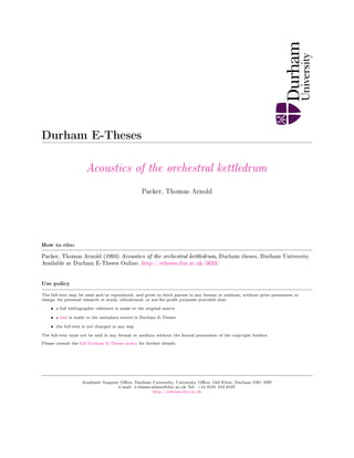
  • 9. Introduction This Thesis is concerned with the acoustical properties of the orchestral kettledrum. The usual kettledrum, often referred to by its Italian name timpano (plural timpani) in musical scores, consists of a hemispherical bowl of fibreglass or copper over whose open part a membrane is stretched, normally of calfskin or a plastic ^ material. By means of screw attachments or a foot pedal mechanism the tension of this membrane can be altered. The drums are available in several standard sizes, the most common being a pair of diameters seventy—one centimetres and sixty-four centimetres (28 and 25 in). Others are used in more ambitious scores with diameters of seventy-six, sixty-six and fifty-eight centimetres (30, 26 and 23 in) to supplement this usual pair. Sadie (1984) gives more details of the construction of these instruments. On striking the drum, off centre, at about a quarter of the way between the rim and the centre, with a suitable stick, often haying a soft, felt covered head, the instrument produces a musical note of identifiable pitch, the actual pitch depending on the size of the drum and the tension of the membrane, enabling the drums to contribute to the orchestral colour and harmony. The range of the usual pair is shown in figure I . l . large drum (71cm) small drum (64cm) - j-^ o 87 Hz 131 Hz 117 Hz 174 Hz Figure I . l Range of the orchestral kettledrums Mylar or I C I Melinex (Polyethene Terephthalate): see Appendix B.
  • 10. The musical role, history and performing techniques of these instruments are adequately covered by Blades (1973a and 1975). At the bottom of the hemispherical shell there is a small hole (of radius approximately one centimetre) to equalize the pressure inside and outside of the drum in the event of a change in atmospheric conditions. It is suspected by some authors that this produces a significant effect on the sound produced (eg Benade 1976a) whilst other maintain that it has little or no effect (eg Rossing 1982a). However it is apparent that the cavity itself, as well as contributing to the aesthetic appearance of the drum, affects the sound produced. This thesis attempts to explain how the membrane will behave when struck and to investigate the effects of air damping, the bowl and the hole mentioned above to give a theoretical sound spectrum. Comparison with the harmonic series may then give an insight into the tone colour to be expected and to estabfish the nominal pitch of the drum, often the source of debate amongst musicians, eg Berfioz (1844). Rayleigh (1945a) produced expressions for the behaviour of a stretched membrane; much of his theory still stands and has been utifised here. Certain misconceptions on his part led to an error in his treatment of a mass loaded membrane (Rayleigh 1945b) and this has been perpetuated by others (eg Morse 1948a). The correct treatment has been suggested by Kornhauser and Mintzer (1953a). Benade (1976b) has produced tables of frequencies based on experimental results, although he does not give any procedural details. More recent research by Christian et al (1984a), which concentrates especially on the problems associated with air damping, also gives tables of frequencies, based on both practical observations and theoretical calculations. Rossing (1982b) and Fletcher and Rossing (1991a) have produced tables showing the effect of the size of the bowl of the instrument.
  • 11. - 10 In short, the mathematical treatment of the vibrations of a stretched membrane in a vacuum is well understood; the more specialised problems encountered with kettledrums are not so well documented. This thesis is intended to address these problems and to bring together the work of other authors on the subject. Section 1 deals with the vibration of a stretched membrane not subject to any restrictions or damping forces. Section 2 introduces a suggested function to define the initial displacement that the membrane might suffer when struck with a typical drumstick. Section 3 takes into account the effects of the cavity, assuming some kind of average displacement of the membrane; various treatments of this cavity problem are advanced, each with its own assumptions and conditions. Section 4 deals with the air damping of the system. In Section 5, consideration is given to other effects: the mass loading effect of the drum stick and the stiffness of the membrane. Section 6 deals with the time development of the system and radiation effects. The whole thesis should be read bearing in mind the discussion of Section 7 which is based on observations made by performers and comments on the sensations of pitch, together with experimental results showing the frequencies of the important modes of vibration.
  • 12. Section 1 11 - Vibration of a stretched membrane in a vacuum This section deals with the modes of vibration of a simple, circular membrane, not subject to any restraining forces and firmly fixed around its perimeter. 1.1 Derivation of the wave equation for a stretched membrane and of the normal modes of vibration^. Although polar co-ordinates will be used to specify points on the membrane's surface later, the initial wave equation is simpler to derive using cartesian co-ordinates, in which the displacement y is expressed as y = y(x, z, t) where x, z defines a point on the surface and t defines the instant in time. The membrane will be assumed to have negfigible stiffness, to be perfectly elastic, to be of uniform thickness and to be subject to small displacements. I f o is the area density (in kg m'2) and T the tension (in N mi) to which the membrane is stretched at its edge, then the net force acting on the element dS { - dx.dz) due to the tension along the sides dz is Tdz x+dx which reduces to 52y dxdz 2 Similar calculations are to be found in Raleigh (1945a) and Kinsler and Frey (1962a).
  • 13. 12 and that due to the tension acting along dx is 52 5i dxdz (refer to fig 1.1) (The tension will be distributed uniformly throughout the membrane, so that the material on opposite sides of a line segment dl will be pulled apart with a force T.dl Newtons). Tdx Figure 1.1 Element dS under tension T This restoring force will equal the product of mass and acceleration, the mass d^v being a dx dz and acceleration Hence dx dz = o dx dz or d2y dt^ = r2 (1.1) (1.2)
  • 14. 13 where T a (1.3) c in fact being the speed of propagation of transverse waves in the material. Polar co-ordinates may be used with advantage when deafing with this circular membrane. Equation (1.2) may be expressed more generally as (1.4) In the case of the circular membrane having a fixed boundary of radius a, it is necessary to express in terms of the polar co-ordinates, r and 9, where X = r Cos^ and z = r Sin^. By partial differentiation with respect to r and 0, the operator is found to be: y2 - 52 1 5 , 1 52 (1.5)= Substitution into (1.4) gives dF - ^ ^ + F ^ + F^ 1 52 (1.6) The boundary condition imposed on this equation is that the displacement must be zero at the circumference, ie y = 0 when r = a. Assuming that y is a harmonic function of time (ie y is proportional to Cos {ut — e)) and writing ^ as k (17) ^ Similar calculations are to be found in Raleigh (1945a) and Kinsler and Frey (1962a).
  • 15. 1 4 - Whatever y's relationship with r and 0 it can be expressed as a Fourier series y = yo + y i Cos {0 + ei) + y2 Cos2 [0 + 62). (1.8) in which yo, y i , etc are functions of r but not 0. Substitution of (1.8) into (1.7) gives: Yn Cos n{0+ en) = 0 (1.9) for all integral n 0 . Multiplying both sides by Cosn((?+ en) and integrating with respect to 0 between fimits of 0 and 2ir, each term must vanish separately, and thus it is possible to determine y n as a function of r. d ! y n , I d v n , [ k 2 - ^ ^ yn = 0 (1.10)^ The solution of (1-10) involves two distinct functions of r each multipfied by an arbitrary constant. One of these functions becomes infinite when r becomes zero, and hence the corresponding particular function may be excluded as it does not satisfy the prescribed conditions^. The other solution satisfying (1.10) is Bessel's function of order n (denoted by Jn(kr)) and may be expressed in several ways^ ^ I t makes no difference whether Cos n (^ + fn) is included in yn or not. ^ Rayleigh (1945c) gives examples of this situation. ^ The properties of Bessel Functions are appended to this thesis, Appendix A.
  • 16. - 15 In accordance with the usual notation for Bessel functions the expression for the vibration of a normal component may be written as: y = PJn(kr)Cos n(?+e)Cos (wt + 7) (1.11) the boundary condition requiring that Jn(ka) = 0 . (1.12) The complete solution for y is obtained by combining all the possible solutions embodied in (1.11) with all permissible values of n and k. As a function of r and 9, y can be expressed within the fimits of the circle radius a in the series y = ^ ^Jn(kn,ir)^^n,iCos n^? (1.13) 1 n where (kn,ia) is the i'^zero of Jn(kn,ia) n = 1, 2, 3 etc. For every integral value of n there is a series of values for k given by (1-12) and for each of them (pn,i is arbitrary. The estabfishment of these constants can be achieved in the following manner. The energy of the motion is equal to p ( f y2rdrd? where p is the density of the membrane and when expressed by means of normal co-ordinates it can only involve their squares, it follows that the product of any two terms in (1.13) becomes zero when integrated over the area of the membrane. Multiplying both sides of (1.13) by Jn(kn,ir)Cos(n^?)r and integrating
  • 17. 16 /.a /,27r a 27r 2 / / yJn(kn,ir)Cos(n^?)rdrd?= / / ?in,irJi.(kn,irl Cos2(n?)rdrd^ •^0 -^0 -^0 -^0 L . J (1.14) the right—hand side reduces to a 2 7r?in,i / rJn(kn,ir)l rdr (1.15) •^0 L J j - 2 ^2 2 J n ( k n , i r ) l rdr is found to be^ f J +.(kn,ia)l . Hence the n L J ^ L J 2 | J n ( k n , i r ) | rdr is found to be? ^ | Jn,i(kn,ia) | '0 values of the coefficients (pn,i (n = 1, 2, 3 ... i = 1, 2, 3 ..) can be determined from J f yJn(kn,ir)Cos(n/?)rdrd^ 0n,i = • (1.16) 7ra2 2~ J n n ( k n ' i a ) The displacement of a membrane, then, can be expressed as the sum of a set of normal modes, whose ampHtudes are easily determined. 1.2 Determination of the form and frequency of the normal modes^ Consideration of equation (1.11), rewritten here for a specific mode, (n, i) shows the character of each mode. yn,i = ^n,iJn(kn,ir)Cosn?Cos wt . ( l . 17)=(l. 11) See Appendix A 8 Similar calculations, extending to annular membranes are to be found in Gray and Matthews (1895a)
  • 18. - 17 Each element of the membrane will exhibit simple harmonic motion of period — . The frequency of oscillation is therefore •' 2n 27r 27r r r a ' The amplitude of this element is (1.18) see (1.3) (1.7). A = (^n,iJn(kn,ir)Cos n^ (1.19) which vanishes, and the element accordingly remains at rest if or i f Jn(kn,ir) = 0 CosnO = 0 (1.19a) (1.19b) The first is satisfied not only at r = a but also when r = r = r '^n ' ( i-i) ^ kn,i (1.20a) Consequently there is a series of (i - 1) nodal circles, concentric with the fixed boundary. The second equation (1.19b) is satisfied when 6 = 2n (4n-l)7r - 2ir^ (1.20b) giving rise to n nodal diameters, dividing the membrane into 2n equal sectors,
  • 19. 18 - all vibrating in precisely the same way, alternate sectors moving in opposite directions. Figure (1.2) gives a representation of the motion experienced by such membrane. (Some excellent photographs, showing some of the normal modes, obtained by sprinkling sand on to a timpano are appended to Rossing (1982a)). (0.1) ( 1 . 1 ) — . (1.2) — (0.2) (0.3) (2.1) Figure 1.2. Shapes of some of the normal modes of vibration of a circular membrane (Arrows point to the nodal lines) Having ascertained that the displacement of a membrane can be expressed in terms of its modes, it has been shown that it is then possible to determine the natural frequency of each of these modes and their associated shapes. The relative amplitudes of the modes will depend on the initial displacement of the membrane, dealt with i n Section 2.
  • 20. 19 Section 2 Deformation of a membrane under a drumstick This section deals with the shape of deformation caused by striking the drum at a point other than its centre. 2.1 The displacement at any point on the surface of a membrane due to a deformation at a specified position using the method of images. Figure 2.1 A membrane of radius a struck with a force at a distance b from the centre For an infinite membrane, the pressure, P(r), is given by: TV2'^(r) = - P ( r ) (2.1) where V'(r) is the displacement at r due to P(r). For a point force F at b: TV2'^(r) = - F ( 5 ( r - b ) (2.2)
  • 21. 2 0 - the solution of which gives as = 2 ¥ J ^ H ^ - ^ ) (2.3) where T is the tension of the membrane as defined in Section 1.1. For a finite membrane, the method of images can be used to obtain an expression for the displacement, ip, in terms of the initial force, —F. ' The method follows the usual pattern employed in electrostatics problems of this nature (Bleaney and Bleaney (1989)). The method of images enables the boundary condition at the perimeter to be met; an image force +F is introduced outside the membrane at a distance c from the centre to yield zero displacement at the edge. Figure 2.1 shows this situation. The displacement due to a point force - F evaluated at the boundary point P is i)_ = In(a2 + b2 - 2ba Cos 0)^ + A_ (2.4) and that due to +F at P is = ^l^j^ ln(a2 + c2 - 2ac Cos f)^ + A_j_ (2.5) where A_ and are arbitrary constants. The net displacement is therefore ijj= tjj_^ + 2 ^ In a2 + b2 - 2ab Cos 0 a2 + c2 - 2ac Cos (J + A _ + A ^ . (2.6)
  • 22. 21 - The requirement is that P, being situated on the boundary, must have zero displacement. To achieve this, the ratio a2 -f b2 - 2ab Cos 0 a2 + c 2 - 2 a c Cos 0 must be independent of 0; that is to say a2 + b 2 - 2 a b Cos 0 _ /o a 2 + c 2 - 2 a c Cos 0 ^ ^^•^) where k ' is a constant. Rearranging equation (2.7), a2 + b2 - 2ab Cos 0 = k'(a2 + c2) - 2k'ac Cos 0 (2.8) or a2 + b2 - k'(a2 + c2) + (2k'ac - 2ab)Cos 0=0 (2.9) for which the coefficient of Cos 0 must itself be zero, i.e. k' = ^ (2.10) then since it follows that hence a2 + b 2 - k ' ( a 2 + c2) = 0 (2.9a) a2 = cb (2.11) k ' = 1^ (2.12)
  • 23. 22 the displacement, ip at the boundary therefore follows as ^ = 2 i T In a + A_|_ + A (2.13) -F b and choosing A . + A as 75-^^ In - gives zero at the boundary. The general displacement at a point (r, 0) will be In r2 + b 2 - 2 b r Cos 6 r 2 + c 2 - 2 r c C o s 0 1 a (2.14) with c h It has been intimated by Morse (1948b) and Kornhauser and Mintzer (1953b) that a point force or one whose radius of contact is F/2 ttT, would cause the membrane to break. Thus the expression obtained above is only valid if the force is taken over a finite area. Fortunately this is exactly what happens when the skin is struck with a typical drumstick. The shape of a common stick is shown in figure (2.2) Figure 2.2 Usual form of a kettledrumstick The displacement given in equation 2.14 is hence invafid for a point within the area of contact; the displacement for such a point will be equal to the initial displacement caused by the stick's blow. Outside the area of contact the displacement is given by (2.14); a discontinuity is introduced at the edge of the area of contact.
  • 24. 23 2.2 Deformation of a membrane deriving from an impulsive force In the foregoing description of Section 2.1 it has been assumed that the membrane is released from a static position, from which it is released to perform the vibrations described in Section 1. The case of the stick producing an impulse rather than this static deformation will not be considered for intuitive reasons; the mass of a stick is considerably greater than the mass of a typical membrane (which, after all, has been taken as massless in the treatment of Section 1) and practical experience of playing these instruments which shows that the skin produces a definite upward force to the drumstick, which assists playing technique. This effect will give rise to a mass—loading of the membrane for its first half cycle. (Section 5).
  • 25. 24 Section 3. Considerations of the effect of the cavity upon the modes of vibration This Section attempts to suggest ways in which the cavity behind the membrane in a real situation may adapt the behaviour of the drum. 3.1 Membrane coupled to a Helmholtz cavity. Treating the kettle as a Helmholtz resonator, and examining the coupling between the membrane and this cavity produces expressions to amend the natural frequencies of Section 1. Damping can also be introduced; damping may occur due to the energy losses associated with the movement of air through the small hole at the bottom. Figure 3.1 shows such an arrangement. Opinions differ as to the importance of this hole in the overall sound spectrum (Benade (1976a), Rossing (1982a)) area A effective length 1' radius b Figure 3.1 Cross Section of a kettledrum The membrane's movement is denoted by y, and that of the air through the hole by x. Rayleigh (1945d) gives the expression for the effective length of the air plug of a Helmholtz resonator in the case of a small circular aperture in a thin wall as
  • 26. - 2 5 r A 2 ¥ ( 3 . 1 ) where A is the area of cross section of the hole, b is its radius, 1' is the effective length. Helmholtz (1912) and Wood (1953) give details of the principles involved in the resonance of such a cavity, such as the one under consideration here. The equation of motion of the air plug is ^ . w d2x , A n dx c2A Ax - J* ^ ds (3.2) where pa = density of air X = displacement of air plug = displacement of membrane D = damping constant c = velocity of sound in air. The flow of air through the hole is damped by viscous forces acting at the opening; dx these are accounted for by the D ^ term in (3.2). Defining an average displacement, y for the membrane of radius a y = ^ / ^ d s (3.3) and from (3.3) and (3.2) d2x , p. dx , c2Ax c2 , (3.4) the equation of motion of the membrane is
  • 27. -26 P n , h ^ Ax - J Tp ds (3.5) where h = thickness of membrane Pni = density of membrane ip can be expressed as the sum of the normal modes of the membrane (Section 1) = Y J ^^^^ (3.6) where (pi is a mode ai is the ampfitude. As an approximation J ipds = ^ a-i J ' (pids - M j $!'ods (3.7) The last approximation deriving from the fact that the fundamental is the only mode without nodes, (apart from the perimeter) hence only is coupled to the resonator in this approximation. By considering the fundamental alone, and averaging the equation of motion over the area of the membrane gives: ,,2 , PaC^ , 7ra' P-A c2Ax /9,n V h (3.8) where u)m — frequency of fundamental. The resonant frequency of the cavity, according to Helmholtz (1912) and Wood (1953) is - ^2 (3.9)
  • 28. - 2 7 - Two constants, a and P are defined, such that a 7ra^ AT and P ^ ^ using these in (3.4) and (3.8) and trying solutions of the form x = xoei'^^'', y = yoe^^*^ the following identities are obtained: CJ^XQ + iwDxo + WcXo = aulyo (3.10) w2yo + (wm + apojl)yo = Puho (3.11) For this solution to be non-trivial, the value of the determinant Lj^ — i wD — Lol Pul u/ -{UJI + aPul) must equal zero, i.e. [iJ - iwD - UI){LJ^ - [ul + aPul)) - aPuf: - 0 . (3.12) Its solution leads to the two normal mode frequencies. For the lossless case (D = 0) an examination of equation (3.12) shows that one normal mode frequency will be greater than the larger of Wc and J ul + aPcol, whilst the other will be less than the smaller of these.
  • 29. - 2 8 The frequency of the fundamental will therefore be altered by a factor of 1 + if the damping factor is taken as zero. (The resonant frequency of the cavity is found to be about 25Hz.) The justification for considering only the fundamental in the approximation of (3.7) was that any one of the modes with nodes will not produce a comparable volume change. Certainly all modes having diametrical nodes will produce no volume change whatsoever. This gives rise to the fact that the fundamental is not only the most seriously affected by the cavity in terms of a change in natural frequency, but must also be the most seriously affected by the damping effect of the air moving through the small hole. 3.2 Membrane coupled with a closed cavity. In this treatment the kettle is considered as being an airtight cavity. This approximation will be better for the higher modes that involve a volume change that is small compared to the volume of the cavity. If the speed of transverse waves in the membrane is considerably less than the speed of sound in air, then the compression and expansion of the enclosed air will be more or less the same over the whole extent of the membrane, and will depend on the average displacement of the membrane. When the membrane is displaced from equifibrium to a shape determined by V) the volume of the vessel is diminished by
  • 30. 29 - a 27r A V = j j ilKdidO . ( 3 . 1 3 ) ' 0 0 If the equifibrium volume is VQ and density po then when the alternations of pressure within the vessel are large enough to be adiabatic, the excess pressure inside the vessel will be r 2-1 . a 27r P = - ^ C f ^dvdO (3.14) where Ca is the speed of sound in air. (The minus sign originates from the fact that the pressure is in the opposite direction to the displacement of the membrane.) The equation of motion of the membrane is, therefore 2 T . a ^27r f f M^dO ( 3 . 1 5 ) V o l J ^0 -^0 where c is the speed of transverse waves in the membrane. For simple harmonic vibrations ip = Y(r, ^)e-i^t V2Y + ^ Y = 2 2 T . a 27r f f YvdxdO . (3.16) V o l J ^0
  • 31. 30 If Y = Sin (n^?)Jn( — ), n 0, the integral on the right-hand side will be zero (owing to the integration over 0), and the solution that satisfies the boundary conditions Y = 0 at r = a will be the solutions derived in Section 1, with the corresponding allowed frequencies. The presence of the airtight cavity does not, then, according to this treatment, appear to affect the normal modes having one or more diametrical nodes (i.e. n 0). If n is zero then the integral on the right-hand side of (3.16) is not zero. The solution without the integral is Jo( ^ ) so trying the solution Y = Jo( ^ ) — Jo( ^ ) which satisfies the boundary condition, the integral reduces to wa f Yrdrd0= '0 O c wa c~ Jo C (3.17) where x = Mch'/V^T) substituting this into equation (3.16) and using the properties of Bessel functions, (see Appendix A ) , gives: T - ^ -r fbJSis 2c f /waJ _ -X T /was (3.18) This equation determines the allowed values of the frequency for those normal modes that are independent of 0 (i.e. having no nodal diameters). The constant x is a. measure of the relative importance of the cavity with respect to the tension, as a restoring force on the membrane. The limiting case x = 0 is
  • 32. - 3 1 the one studied in Section 1. Morse (1948c) gives a table showing how the frequency varies with x- The presence of the vessel tends to raise the frequencies. Sen (1990) has produced a similar expression for allowed frequencies; his result is identical to that of Morse (1948c). Morse (1948d) gives an approximate formula for the frequency, vafid for small values of x as f - - fo 1 + Poc|T (3.19) where fo is the frequency when X is 0 a is the area density of the membrane. Kinsler Frey (1962a) in a similar treatment of this problem define a constant ra 7 a = (3.20) • where PQ is initial pressure 7 is ratio of heat capacities of air which is again an expression for the importance of the cavity. A similar expression is arrived at for u Jo wa ~c ( wa ^ - a J , ^ ^ 2 (3.21) from which it is evident that x and a are equivalent. Table 3.1 shows the frequency modification factors for various values of x and different modes, derived from (3.19).
  • 33. 32 - X Frequency modification 0 1.0 0.5 1.041 86 1 1.082 11 2 1.158 40 3 1.229 97 4 1.297 60 5 1.361 87 6 1.423 25 8 1.538 68 10 1.646 03 Table 3.1 Frequency modification due to a Helmholtz cavity Frequency modification X (0,1) (0,2) (0,3) (0,4) 0 1.0 1.0 1.0 1.0 0.5 1.029 39 1.001 080 1.000 145 2 1.000 026 6 1 1.037 74 1.002 220 1.000 326 7 1.000 079 9 2 1.111 69 1.004 553 1.000 726 1 1.000 186 5 3 1.162 51 1.007 000 1.001 089 1 1.000 293 1 4 1.210 32 1.009 561 1.001 488 4 1.000 399 6 5 1.254 60 1.012 293 1.001 887 1 1.000 506 2 6 1.295 10 1.015 139 1.002 287 1 1.000 612 8 8 1.364 67 1.021 285 1.003 122 1 1.000 825 9 10 1.450 16 1.028 115 1.004 029 5 1.001 103 9 Table 3.2 Frequency modification due to a closed cavity
  • 34. - 3 3 3.3 The effect of the size of the cavity. Experimental evidence shows that reducing the size of the cavity produces significant effects on the frequencies of each of the modes. Rossing (1982c) shows that reducing the volume of the cavity by a quarter produces little effect, whilst reducing the volume to a half, and then to only one—quarter of its original size produces a dramatic shift in frequency. The volume was altered by part filling the drum's cavity with water. Christian et al (1984a) give measured results which are reproduced in Section 7, together with a tentative theory as to the importance of the cavity volume^. Figure 3.2 shows the effect of altering the volume for some of the modes. (From Fletcher and Rossing (1991b).) 337 Hz 385 Hz 537 Hz 655 Hz 566 Hz 747 Hz 816 Hz i 2 S t 313 Hz 771 Hz 515 Hz 644 Hz 705 Hz (322 Hz) J ^ 518 Hz 642 Hz 706 Hz Figure 3.2 Normal modes for three different air volumes 9 See Section 4.2.
  • 35. 34 3.4 The effect of the kettle as a baffle. The fact that the kettle only exists on one side of the membrane effectively prevents any sound from being radiated from the underside of the membrane. The (0, 1) mode will therefore act as monopole source, radiating sound waves outwards in a hemispherical manner from the upper surface of the drum. Without the kettle, it would, of course act a dipole source. The other modes, however will act as multipole sources; the ( 1 , 1) mode for example will be a dipole source, the (2, 1) mode a quadropole source. This action of the kettle has several implications. In the first place, the sound radiated from the underside of a membrane without the kettle as a baffle will be exactly half a cycle out of phase with that radiating from the top, thereby causing interference, and the sound would not be as efficiently radiated in the plane of the membrane. As it is, the kettle effectively cuts off the sound from the underside, thereby leaving the sound from the upper side to radiate well. Another acoustical characteristic is that sound from a monople source radiates with great efficiency, which implies that the vibration giving rise to this monopole source will die away much more quickly than that from dipoles or quadropoles. This suggests that the fundamental (0, 1) mode will not have a long time duration. 3.5 General considerations. The fundamental frequency of the membrane from Section 1 is 2-404 '^in = — r — y (3.22) (2-404 is the first zero of Jo) hence
  • 36. - 3 5 1 ^ l(0-777r)' (3.23) The parameter x has been defined as and so X 7rp 0 c ^ a* VoT (3.24) X •Kpoch^ _ 2-404^ (3.25) X = po c^Tra^ _ 2-404^ /5m Voh 2 (3.26) /)ni is density of membrane ( = ) ;^ = 2-404 V X = 5 - 8 5 a ; 0 ^ (3.27) (3.28) a and ^ are defined in Section 3.1. The theory of Section 3.1 gives the frequency as /• _ Win ^ - 2^ (3.29) in the closed cavity limit. The frequency in this case has modified the cavity-less value by a factor of or 1 + X5-85 Comparison of this with the results of
  • 37. 36 - Section 3.2 shows reasonable agreement at least for the lower values of x - Table 3.1 shows the modification to the frequency according to the theory of Section 3.1; it should be compared with the results shown in Table 3.2. Other coupfing effects will be experienced by the system; the higher frequencies of the drum will couple with the spherical modes of the cavity. These modes can be expressed by means of spherical Bessel functions, but the relatively low amplitude of most of the affected modes does not render a full treatment worthwhile at this stage. It has been shown in this section that the frequencies of all modes that have no nodal diameters are affected by the cavity. A constant x has been defined, giving the relative importance of the cavity to the system. In all cases for which X 0 the cavity has the effect of raising the frequencies of these modes. In addition there is a damping factor due to the viscous effect of the air being forced through the small hole at the bottom of the cavity by the vibrating membrane. This factor again only affects the modes with no diametrical nodes, reducing their amplitude; it is suspected that since this effect must depend on the volume of air the membrane displaces that this damping will be far more apparent on the fundamental than on any other modes. By far the greatest effect of the cavity, however, is as a baffle, causing the fundamental (0, 1) mode to be a monopole sound source, and therefore die away quickly. However, air damping, (Section 4) can be shown to have a far greater impact on the frequencies of the modes of vibration, as well as affecting their amplitudes and decay times.
  • 38. - 3 7 Section 4. Air Loading This section deals with the modifications to the normal modes due to air loading, using a Green Function technique. 4.1 Modelling the Air Loading using Green's Functions. It is suspected that air loading alters the normal mode frequencies by a greater degree than any other factor. Rayleigh (1945e) recognised that the frequency ratios actually obtained from a kettledrum deviated significantly from the ideal ratios of a membrane vibrating in a vacuum, derived in Section 1. His suspicions were confirmed by Benade (1976b) who found that the first ten components of the sound spectrum had frequencies closely adhering to the harmonic series, without the fundamental. A discussion of the importance of the harmonic series, and its role in giving rise to a sensation of pitch is to be found in Section 7. To estimate the effect of air loading, the effective mass of loading a piston in an infinite baffle is given by Kinsler and Frey (1962b) as m 7ra^ PoCa — X (4.1) where x is the piston reactance function Po is the equifibrium density of air Ca is the speed of sound in air for frequencies f ^ J ^ Arr:47ra X 16 /a T c a so m = 2 Pod}. This is equivalent to the air in the form of a disc, with the radius. 8a a, of the piston and thickness A t higher frequencies the air load decreases as
  • 39. 38 j^, so above 500Hz the air load becomes negligible. The effective mass loading on a rigid baffled piston would therefore shift the frequencies by as much as 40 per cent. A more exact determination of the effects of air loading can be made by applying the Green Function technique'°. The kettledrum is considered as a rigid cylindrical kettle of length L and radius a, capped by the membrane, and with a rigid bottom, except for the smaU hole mentioned in Section 3. Christian et al (1984b) give details of this technique. 1 52 The incremental pressure P of the air satisfies the wave equation P = 0 . (4.2) For a given normal mode the pressure may be written as P = P(r)e-i'^t (4.3) with P(r) = 0 . (4.4) Air loading inside the kettle may be accounted for using a Green Function, suitable for solving the Neumann Problem (Dettman (1984a)). For points inside the kettle the Green Function, Gi„(r, 6, z, r' O'z') with (r, 0, z) being general cyUndrical co-ordinates and {r',0z') the co-ordinates of the displaced membrane giving rise to the pressure, satisfies the equations (e.g. Pozrikidis (1992a)): ^° Appendix C gives some properties of Green's Functions. Kreisig (1988b) gives the derivation of the operator V2 for cylindrical co-ordinates.
  • 40. - 3 9 - Gin(r,r') = 1 d r 'BT d] . 1 d , 52 m2 Gin(r,r') = - 4:-K5 r - r' (5((?- ^?')^(z-z') (4.5) where 6 is the Dirac Delta Function and from the general properties of Green's functions, eg Pozrikidis (1992b) and Dettmann (1984b) Gin(r, ?,z, r ' , 0',z') = GU^'0'z',r, 0, z) (4.6) and Pozrikidis (1992c) 5Gin(r, I') (4.7) r = a = 0 , L Equation 4.7 is a boundary condition required for a Green Function which can be used to relate the pressure P ( r ' ) inside the enclosure to the boundary values of the normal pressure derivative. Gin(r, r ' ) may be calculated using eigenfunction expansions for the air inside the kettle. Using the cylindrical Bessel function of Section 1, but whose derivatives vanish at r = a: - -|rJn(bH,ir) = J;(bn,ia) = 0 ' i r=a (4.8) and the differential equation of Section 1 (equation (1.10)) d2 , 1 d F^ Jn(bn,ir) = 0 (4.9)
  • 41. 40 - and given the recurrence relation for Jn (Appendix I , equation (A—xii)), it can be shown that J rJ^(b,„ir)dr = | ^ 1 - J2(b„,ia) . (4.10)'^ Because ^—ein6jj,(bn,ir) is complete in (r, ^) space n=oD , , - n , A 4 ^ ^ 2 J n ( b n , i r ) J n ( b n , i r O n = - ( B 1-1 K - 5 ^ l J n n b n , i a ) (4.11) hence G^^{T, T') may be expressed as the left-hand side of (4.11) with an extra factor gn,i in the sum, provided that d , W2 4- ^ - h 2 • gn,i(z, z') = - 4 7 r ( 5 ( z - z ' ) (4.12) and g„,i(z, z ' ) = gi„i(z', z) (4.13) and 3 ^ g n , i ( z , z ' ) = 0 z' = 0,L (4.14) so that equations 4.5, 4.6, 4.7 are satisfied. Morse (1948e) gives a similar relationship.
  • 42. - 4 1 - Equations 4.12 to 4.14 are satisfied by (from Morse and Ingard (1968a)) gn,i(z, z ' ) = 47r 7n , i :Sin(7n,iL) Cos(7n,iZ^)Cos(7n,i[L-z^]) (4.15) where z^ is the greater of z and z' and z^ the lesser, and 7ri) i — 7n)i i f ^ _ K 2 . 7^ b,1,i for bn,i ^ b , l i - 7^ for bn,i (4.16) The Green function inside the kettle, Gn,i(r, 0, z, r' f , z') is therefore given by G,n(r, r ' ) QD • X — 47r ein(e-e', y 2 J A , i r ) J „ ( b n , i r - ) C ° ^ ( ^ ' ^ V ) ^ ° ^ [ ^ ' ^ ( L - ^ ^ ) ] 27r n=—CD i=l a^ m J^(bn,ia) ' ^1 I / i l l I V 7n , i Sin(7„,iLj (4.17) To model the outside air loading will require specific assumptions about the surroundings. I n this treatment the reflections of sound waves from the walls of the room will be ignored and, in addition, a plane, rigid baffle will be assumed to surround the membrane in its plane. This is easily the most un—physical assumption of this section, but it does lead to greater simplicity. Christian et al (1984b) are currently engaged in calculations that do not involve this assumption, but as yet their investigations are incomplete. Prefiminary results, however, indicate that there is good agreement with this simpHfied model.
  • 43. 42 - The Green Function Goiit,(r, 0, z, r ' , 0' , z ' ) for points outside the kettle must have outgoing waves that vanish at infinity and vanishing normal derivatives on the membrane's plane, z = L. A suitable function is equation (4.18) as shown by Morse and Ingard (1968a): G o u t ( r , r ' ) exp- lU) r2 + r ' 2 - 2rr'Cos(^^?') + (z-z')2 r2 + r' 2 - 2rr'Cos( 0-0') + ( z - z ' ) 2 exp i w a + r2 + r ' 2 _ 2TT'COS{0-0') + (z-z'-2L)2 r2 + r' 2 - 2n'Cos{0-0') + ( z - z ' - 2 L ) 2 (4.18) An expression for P(r), the pressure inside or outside the kettle enclosure may now be estabUshed. Multiplying equation (4.4) by G^^{T, r ' ) and replacing r, e, z with r ' , 0', z' G j r , T ' ) V2 + ^ P(r) ^ 0 (4.19) and multiplying (4.5) by P ( r ' ) nT')U2 + ^]G,^{r,T') = -^F{T)6{T-r')5{0-0')6{z-z'). (4.20) Subtracting (4.19) from (4.20) pP{T')6{i-T')6{0-e')5{z-z') ^¥{1') V2+ 7^ G i n ( r , r ' ) - G i „ ( r , r ' ) P(r') (4.21) re—arranging and integrating over the kettle enclosure:
  • 44. - 4 3 - 4-Kf f f 5{T-T']{0-0')iz-z')P{T')dTd0dz = f f / r ' [ p ( r ' ) V 2 G i „ ( r , r ' ) - G i n ( r , r ' ) V 2 P ( r ' ) enclosure dr'd^?'dz' . (4.22) The left—hand side reduces to 47rP(r'), hence: P(^') = - ? ¥ / / / r ' [ p ( r O V 2 G i n ( r , r ' ) - G i n ( r , r ' ) V 2 P ( r ' ) enclosure dr'd(?'dz'. (4.23) Applying the second form of Green's theorem (Kreisig (1988c), Morse and Ingard (1968b)) P(^') = - ? i / / [ P ( ^ ' ) | T G i . . ( ^ ' ^ ' ) - G i n ( r , r ' ) | p ( r ' ) r'dr'd^^' (4.24) surface where ^ is the directional derivative normal to the surface, S, of the membrane. Using the boundary conditions, given by equation (4.7), this reduces to: . a 27r = - r J ^ G a r , r O f ( r ' , ^ ^ ' L _ ) r ' d ^ ' d r ' (4,25) where P(r',^?',L_) is the pressure on the kettle side of the membrane. A similar calculation for . the pressure outside the kettle can be derived,
  • 45. 44 substituting r, z for i 0 ' , z ' and using Gout(r,r') from equation (4.18): a 27r P W = - ? ^ / Q / Q G o , . t ( r , r ' ) § ( r ' ? ' L O r ' d / ; ' d r ' (4.26) where P(r',(?',L+) is the pressure on the outside of the membrane. Christain et al (1984b) extend these expressions for the pressure without the kettle and baffle (i.e. an isolated air-loaded membrane). The results are consistent, insofar as the expressions show that in the plane of the membrane a wave from the underside exactly cancels one.from the upper surface, which is of course clearly the case. 4.2 Determination of the normal modes. From equation (1.10) and including the effects of the pressure both inside and outside, the displacement ip of the membrane satisfies the equation = - o u ^ = T 7 2 ^ + P ( r ' ) - f P(r) (4.27) ip = •0(r, 0) e-it^t ^ = - u^tpir, 0) e-iu't (4.28) hence and a and T are the area density of the membrane and the tension respectively, as defined in Section 1.'
  • 46. 45 Linear fluid dynamics gives dF poi^ = - P o w ¥ = - -57 (r, 0, Z, t) (4.29) where po is the equilibrium density of air. From Section 1 (equation 1.14) the loaded displacement function, ij), can be expressed as the sum of the normal mode displacements, i.e.: ^(r, 0) - V ^(^,n,s'0'm,s(r, 0) m=0 s=l where tl)' is the in vacuuo displacement function. (4.30) Substitution of the expression for the pressure inside the kettle enclosure and outside into (4.27), and bearing in mind that c2 = T / a (equation (1.3)) a I'K ^ ( ^ ' ^) = OT/Q / Q Gin(r,r')||(r',(?',L_,t)r'd?'dr' .a 27r + ?Zr/o/o G o 4 r , r ' ) f ( r ' , ^ ' , L ^ , t ) r ' d ^ ' d r ' (4.31) ap.Using the relationship between ^(r, 0) and - ^ r , 0, z, t) (equation (4.29)), and given that P ( r ' , ?', L ^ ) = - P(r', i / ' , L J gives V2 + 7^ 2 /.a -27r = f G i „ ( r , r ' ) ^ ( r , %'d?'dr' 2 a 27r / Gout(r,r')^(r, %'d^?'dr' . (4.32)
  • 47. 4 6 - The original in vacuuo displacement function, ip'{i, 0) has the orthonormal property: .a 27r / / ^'p,q(r, ?)^'„,n(r, 0)iAOAi = 6^J^u (4.33) *^0 -^0 where 6 is the Kronecker delta function. So re—writing equation (4.32) for an individual mode, •^/'ni,.s(r, 0), substituting for Gin(r, r ' ) and Gout(r, r ' ) (equations (4.17) and (4.18)), multiplying both sides by ^ ' ( r , 0)i and integrating with respect to r and 0 over the membrane's surface gives 2 ^ i n , S _ 1.2 GO 00 ^o^iriis ^ kill,II kill, q 7ni)n Cot (7m,nL) 011, s q_-[^ (km,s ~ biii,n )(kiii , q — b|n,ri ) (1 4£c . . ^ ~ t t •• •• •• • ' TT- h 2 CD ^ ^ 0n,s I,n,s,q (4-34) q=l where kni,s is the s^h zero of Jni(kn„sa) = 0 and In„s,q= r^r^''r^r^''Gout,(r, r')^m,s(r, 0)i),,{i, 6 ) u ' A T ' m i : (4.35) •^0 *^0 -^0 -^0 This result uses the series relationship given by Morse and Feshbach (1953a) and the expression for Gout,(r, r ' ) given by Morse and Feshbach (1953b).
  • 48. Ini,s,q reduces to 47 I 47rkm, .00 a L - 2 Jn^,(aA)dA k[n, s ) ( k | n , q ) (4.36) where I )2 ~ C ^ - A = (4.37) The solution of (4.34) give an infinite series of eigenmodes, from which the modified frequencies, uJm,^ can be calculated using numerical methods. Christian et al (1984b) derive similar relationships: they Umit s, q and n to 1, 2, 3 and 4, estimate for a;m,s based on the in vacuuo value and pick out eigenvalues and hence the eigenfrequencies. Comparison and re-substitution for u,„,s is continued until reasonable agreement (about 0-5%) is achieved. Numerical results obtained by these means for a 64cm drum are given in Table 4.1 below: Mode frequency ratio to (Hz) (1,1) mode (0,1) 138 0.80 (1,1) 172 1.00 (2,1) 261 1.52 (0,2) 291 1.69 (3,1) 344 2.00 (1,2) 390 2.27 (4,1) 427 2.48 (2,2) 471 2.74 (0,3) 511 2.97 (5,1) 506 2.94 Table 4.1 The calculated effect of air loading on the normal mode frequencies (Tension: 5360 N / m )
  • 49. - 4 8 From Table 4.1, it can be observed that if the fundamental (0,1) mode is ignored, the remainder of the calculated frequency ratios approximate well to the ideal ratios of the harmonic series, discussed in Section 7.1. Furthermore, it is interesting to note that the calculated values of these frequency ratios for various values of L produce nearly harmonic ratios when L/a = 1.2. This implies that a kettle having internal volume l-27ra3 is the ideal one necessary to produce a musically pleasing sound. Christian et al (1984c) have produced a tentative theory to account for this, but without any attempt to include the details of the kettle geometry.
  • 50. 4 9 - Section 5 Other considerations This section deals with other effects likely to alter the sound produced, namely the mass loading of the membrane and the effects of membrane stiffness. 5.1 Mass loading. The original treatment of a vibrating membrane to which a small mass load is attached was first suggested by Rayleigh (1945b). He calculated the perturbation of the eigenfrequencies by considering the additional kinetic energy due to the mass load, assuming that the eigenfunction was unchanged by this load. This gave a paradoxical result, since the perturbed frequency derived is independent of the area of attachment. Indeed, a finite mass attached to a single point would cause the membrane to break (Morse (1948b)). Rayleigh's (1945b) solution gives frequencies that are lowered by the addition of the mass load. Kornhauser and Mintzer (1953a) have produced a more rigorous solution to this problem. Starting with the equation of motion of the membrane a2y + k2y = 0 (5.1) where y is the displacement of the membrane from Section 1 and the force on the membrane due to the attached mass, m, is given by F = 27rbT^ (5.2) r = b where b = radius of attachment
  • 51. 5 0 - so the equation of motion becomes 27rbT = m - — w^my r=b r=b (5.3) The other solution, is of course, the boundary condition = 0 . r = a (5.4) These two equations, (5.3) and (5.4), combined with (5.1) give a general solution of the form y = AJo(kr) + BNo(kr) (5.5) where No is the Neumann function, or Bessel function of the second kind. The eigenvalue, k, can be calculated from axJo(ax) — 7a2J i(ax axNo(ax) - 7Q:2Ni(axj where Jo(x (5.6) X = ka b a = a 2M 7 = m M = mass of membrane. Thus the eigenfrequencies are dependent on the size of attachment of the mass, m, as expressed in the parameter, a. As a—• 0, and the area of attachment therefore approaches a point, the left-hand side of (5.6) vanishes (because the numerator — 0 and the denominator — i - oo), so Jo(x)/No(x) must vanish.
  • 52. 51 This gives Jo(x) = 0 whose solution gives the unperturbed eigenfrequencies, derived in Section 1. Numerical calculations show that the effect of the mass loading due to an object the size and mass of a typical drumstick raise the frequencies of the significant modes by about 2% When the membrane is struck with a drumstick the stick will remain in contact with the skin until it passes through its equilibrium position after which the player removes the stick. This will have the effect of altering the behaviour of the first half—cycle, in raising the frequencies. However it is to be borne in mind that it is not infrequent to stretch the skin slightly on contact, thus lowering the frequencies, reported by Blades (1973c). The combined effect of the stretching and mass loading is not readily analysed, but confining attention to small forces of striking, thus rendering the stretching ineffective makes the problem simpler, and the expression quoted above can be utifised. 5.2 Membrane stiffness. To account for the stiffness of the membrane, a plate like term can be added to the equation of motion of Section 1. Kinsler and Frey (1982c) give the equation of motion of a thin circular plate as 1^ = T M R ^ ' V ' y ) (5^7) where E = Young's modulus h = thickness p = density 1/ = Poisson's ratio. Combining this with the equation of motion of the membrane (equation (1.4)) gives:
  • 53. 52 - and where T = Tension of the membrane a — mass per unit area c = velocity of transverse waves in the membrane without stiffness = (5-9)12p(l-z/2) Taking the solution to be of the form y = AJn(kr)Cosni? CosuA k= + ! ^ - ^ = 0 (5.10) solving for oj and hence for / ( = UJ/2-K): r _ U) _ Ck ^ . (5.11) Substitution of the values given in Appendix B for a typical mylar membrane shows that the frequency will be raised by about 0.5% by membrane stiffness. This effect is negligible for modes of musical interest. Fletcher and Rossing (1991c) point out that the membrane has a large stiffness to shear, so that it will resist strongly all modes having circular nodes; they resist the type of distortion needed to deflect the membrane without wrinkling it (like wrapping it around a ball). Rossing (1982d) agrees, and explains that this will ensure that these modes, all of which, incidentally, are inharmonic, will have a very small amplitude and decay time, and therefore contribute only to the percussive sound, or impact noise of the instrument.
  • 54. - 5 3 - Section 6. Radiation effects and the time development of the system In this section an attempt is made to explain the effects of sound radiation and therefore subsequent energy loss from the vibrating system, together with accounting for the decay times of the various normal modes. 6.1 Radiation effects. There are four possible ways in which energy from the vibrating system may be lost: radiation of sound; mechanical loss in the membrane; viscothermal loss in the contained air in the cavity and mechanical loss in the kettle walls. The second and fourth of these may be considered negfigible, although the preference for calfskin rather than plastic heads, compared by Hardy and Ancell (1961), and the general feeling that drums equipped with copper kettles sound superior to their fibreglass counterparts may indicate that some loss may indeed take place in the membrane and the kettle walls, although the non uniformity of calfskin heads probably accounts for their superior tone. In particular, the visible line due to the animal's backbone is not terribly elastic, thus encouraging a nodal diameter (Shivas (1957a)). The efficiency of sound production will depend on the net displacement of the surrounding air. With the exception of the fundamental this is very small for the kettledrum, giving it a very low efficiency of sound production for its overtones. The average displacement of a membrane provides one parameter for judging the efficiency for a particular mode. It may be defined as
  • 55. 54 - ^^ = / g ^ ^ % ^ d S (6.1) n will be 0 since for all n 0 there is no net displacement. Since all parts of a ring-shaped element, dS (= 27rr.dr), contained between r and r + dr have the same displacement amplitude, ipi, it is possible to carry out the surface integration by merely integrating over r from 0 to a. h = f%o,i^-^^^^2Tndi (6.2) which upon integration gives = I ^ J i ( k o , i a ) . (6.3) Substitution shows that if the amplitude at the centre were equal for the first two modes (i.e. if 0o,i = ^0,2) then the fundamental displaces three times as much air as the second one. Morse (1948f) gives an expression for the average displacement due to a constant force applied all over the surface; . t ij = f F{T)Ui-T)dT (6.4) -00 where F(r) is the applied impulsive force as a function of time and ^g(t) is the response of the membrane to this force.
  • 56. - 5 5 This predicts that the fundamental mode will be quickly damped but the higher modes will persist. The lower the frequency of vibration the higher the acoustic efficiency, but in addition the higher the radiation damping. As Section 3 pointed out, the presence of the kettle acts as a baffle, and therefore the (0, 1) mode acts effectively as a monopole source, and as such will lose its energy quickly. In the bass drum (this is an instrument which has two membranes of similar size to the kettledrum, mounted over each side of a shallow hollow wooden cylinder of depth approximately 17cm), which is not baffled in the same way, it is interesting to note that the fundamental (0, 1) mode is present in no smafl degree, producing therefore an inharmonic series, and no definite pitch. Fletcher and Rossing (1991d) give an analysis of the bass drum. This comparison, however, shows that the effect of the kettle as a baffle has a considerable part in damping the fundamental. On the other hand, the (1, 1) mode wiU be a dipole source, and wiU therefore radiate sound at a power proportional to and is considerably less efficient, and so losing energy less quickly than the (0, 1) mode. Thus the (1, 1), (2, 1), (3, 1) and (4, 1) modes will decay much more slowly than the others, especially the (0, 1), (0, 2) and (0, 3). The decay times will decrease with frequency, so the (1, 1) and (2, 1) modes will be the most prominent sounds heard. The higher the tension, too, the shorter the decay time wiU be, so drums tuned to high pitches have a short time duration.
  • 57. - 5 6 - 6.2 Time development. A normal mode of vibration (with only outgoing sound radiation) will have a harmonic time dependence e'i^t. The imaginary part, Ui, provides an exponentially decreasing function of time (Goldstein (1980)) and is related to Teo, the time for a 60dB drop in the membrane's sound pressure, given by Using values calculated in Section 4 for w, accounting for the air-loading of the membrane, the decay time, Teo, can be established for each mode. The (0, 1) and (0, 2) modes produce a value for Teo of less than 0.35s, less than the normal reverberation time of a typical concert room, and so their effect can be ignored. Christian et al (1984c) calculated values for Teo; their results are shown for a 64cm drum in Table 6.1. The equivalent measured values are given in the next Section (Table 7.1); the (3, 1), (4, 1) and (5, 1) modes have a shorter Teo than the calculated value, this is accounted for by the other mechanisms for energy losses discussed earlier.
  • 58. - 5 7 mode Teo (0, 1) 0.06 (1, 1) 0.8 (2, 1) 1.8 (0, 2) 0.2 (3, 1) 4.6 (1,2) 0.2 (4, 1) 10.5 (2, 2) 0.8 (0, 3) 0.1 (5, 1) 16.2 Table 6.1 Calculated decay times of the normal modes (Tension = 5360 N/m)
  • 59. 58 Section 7. Observations In this Section, the observed sound spectrum, based on experimental results, of the instrument is considered as well as the sensation of pitch that this produces. 7.1 Pitchi3. It need hardly be said that pitch produces a subjective response, and, of course, there is no guarantee that any two individuals will experience the same sensation. Indeed, many listeners even experience different sensations in each ear, when encountering a pure tone of constant amplitude. The two ears, reported by Burns (1982), can produce a sensation of up to a semitone difference. This having been established, it is, nevertheless true that there is a strong correlation between the perceived pitch as a musical sound and the frequency of that sound's fundamental. All musical sounds are accompanied by a series of overtones, or partials, forming the harmonic series, in which the tones relate to the fundamental frequency, / by 2/, 3/, 4/etc. The harmonic series, based on C is given in Figure 7.1. n ^ j_9_ f 2/ 3/ 4/ 5/ 6/ 7/ 8/ 9/ 10/ 11/ 12/ Figure 7.1 The harmonic Series 13 A fuller discussion of all aspects of pitch and perception is given by Campbell and Created (1987a).
  • 60. - 5 9 - At first sight, it appears that the partials (2/, 3/etc) simply add 'tone colour' to the sound, although some musicians claim to hear each of the constituents distinctly (eg Messiaen (1956)). Randel (1986) maintains that for the psychological identification of pitch, a musical tone must be composed of harmonic partials. Furthermore, he suggests that even if the fundamental is missing entirely, the pitch perceived is that of the fundamental. Experiments by Fletcher (1924) and Wood (1962a) show that, if the fundamental is completely filtered out, the sensation of pitch is still that of the fundamental, in other words the ear appears to 'add' the fundamental back again. It is in this way that a small loudspeaker, for example, is able to give an impression of bass sounds. On the other hand, if the filter is applied to non musical oounda (i.e. thooe whoco partialo ^•f^'^' -do not form a harmonic oorioD), ouch ao human opooch or a onaro drum, the cound bccomoG unrecognisable. Further evidence is that suggested by Munrow (1976), that to most observers the recorder appears to sound an octave lower, (half the frequency) than is actually the case. Parncutt (1989) points out that complex tones (tones that form part of the harmonic series, but with the fundamental missing), produce a pitch that is ambiguous: usually the context of the harmony or melody of which the complex tone forms a part, suggests the pitch to the fistener. In the example of the kettledrum, however, all observations made show that the fundamental is missing, and that the first overtone occurs at a frequency of 1.5 times that of the lowest partial present. Indeed, many musicians find that the pitch of a kettledrum is difficult to define, because of the relative strength of this first overtone (eg Blades (I973b,d)); this can be an aid when tuning the instruments in fifths'* (Blades (1973b)). Most would agree, however, that the nominal pitch of the drum is, in fact, that corresponding to the lowest sounding frequency; the ear does not, in this case, 'add' the missing fundamental of the harmonic series. For a description of musical intervals see Murray Brown (1972).
  • 61. - 6 0 This is contrary to the observations of Parncutt (1989) who states that usually, complex tones without highly audible higher harmonics, will be heard with the fundamental in place. Campbell and Created (1987b) suggest that this is due to the relatively short decay times of the upper partials, leaving the brain with the longest sounding frequency as its only guide. There is, nevertheless, debate amongst musicians, since some perceive the pitch as sounding an octave lower, especially when played quietly (Rossing (1982e)). 7.2 The observed sound of the kettledrum. Rayleigh (1945e) identified the first four sounding frequency ratios as 1.00:1.50:1.88:2.00 and he ascribed the lowest sounding frequency to the (1, 1) mode. Later experiments by Benade (1976a) showed these ratios to be 1.00:1.504:1.742:2.000. In both instances they form part of the harmonic series with the fundamental missing. Rossing (1982f) repeated the experiment and found ratios of 1.00:1.50:2.00:2.44:290, nearly the harmonic sequence 2:3:4:5:6. These observations are consistent with those of performers (eg Shivas (1957b)). The above results are in sharp contrast to the calculated mode frequencies of a vibrating membrane in vacuo, until the air—loading considerations of Section 4 are taken into account, and the fact that the (0, 1) mode is damped completely. It seems, from observations, that all the modes having no nodal radii play little or no part in the sound produced. Striking the drum in the centre, thereby preventing any modes from occurring with a node at that point (i.e. those with radial nodes), produces a pitchless thwack. The drum vibrates for a quarter cycle only; no further vibration takes place. Furthermore, placing a felt damper at the centre, encouraging the modes with radial nodes and discouraging the others, produces no detectable change in the tone quality of the instrument.
  • 62. 61 The most significant practical observations are, then, that the kettledrum produces a near-harmonic series of overtones with the fundamental missing, and that these overtones are due to the modes of vibration having only radial nodes. 7.3 Experimental results. Rossing and Kvistad (1976) have produced diagrams showing the sound spectrum produced by a 63cm diameter drum at various times after striking; their result is reproduced in Figure 7.2 below. J L 0.2 0.4 0.6 Frequency (kHz) 1.0 a) approximately 0.03s after striking at the normal playing position. b) approximately Is later.
  • 63. 62 1 02 04 0.6 Frequency (kHz) 0.8 1.0 c) approximately 0.03s after striking at the centre. d) approximately Is later. Figure 7.2 Observed sound spectra of the kettledrum From this evidence, it is possible to see that the (0, 1) and (0, 2) modes have a short time duration, compared with the others. Even when the drum is struck at the centre, thus exciting the (0, 1) and (0, 2) modes the (1, 1) and (2, 1) modes are more prominent after Is. Christian et aJ (1984d) undertook measurements to ? confirm the theoretical predictions of the air—loading calculations of the mode frequencies and decay times; their results are shown in Tables 7.1 and 7.2 for a 64cm drum.
  • 64. -63 - Mode Frequency Ratio to (Hz) (1,1) mode (0, 1) 140 0.81 (1,1) 172 1.00 (2, 1) 258 1.50 (0 2) 284 1.65 (3, 1) 340 1.97 (1,2) 344 2.00 (4, 1) 420 2.44 (2, 2) 493 2.86 (0,3) 467 2.71 (5, 1) 501 2.91 Table 7.1 Observed frequencies of the normal modes (Tension = 5360 N/m) Mode T6o(s (0, 1) 0.3 (1,1) 0.8 (2,1) 1.7 (0,2) 0.4 (3, 1) 2.7 (1,2) 0.5 (4, 1) 1.7 (2, 2) 0.5 (0,3) 0.3 (5, 1) 2.6 Table 7.2 Observed time decays of the normal modes (Tension = 5360 N/m) Comparison of the experimental values for the frequencies of the normal modes is in good agreement with those calculated in Section 4. Furthermore, when the modes having relatively short time decays, Teo, are eliminated, the frequencies adhere closely to the harmonic series.
  • 65. 64 - Conclusions In Section 1, the normal modes of vibration of a stretched circular membrane in a vacuum were established. Clearly, the origin of the sound produced by a kettledrum must lie in the nature of these modes. In Section 2 the initial displacement function of the membrane was discussed; combining the results of these Sections will give the relative ampUtude and frequency of each of the modes, simply by combining the relevant equations: (1.16), (1.18), (1.19) and (2.14) i.e. A = 0n,iJn(kn,ir)Cos 0 (1.19) where .a 27r rV^ yJn(kn,ir)Cos(n^)rdrd(? ^^^^^ ^ J ^ , ( k , „ . a ) and r2+b2-2brCos(;]^ r2+c2-2rcCos^ y _ kn , i (2.14) (1.18) 27r The subsequent vibration of the membrane, will, however, be altered considerably by several factors. Section 3 examined the effect that the cavity might have, by considering it as a Helmholtz resonator, a closed cavity and as a baffle. It seems fikely that by far the greatest effect it has, is as a baffle. It also appears that the presence of the small hole in the bottom of the kettle (necessary to equalise the equilibrium pressures inside and outside of the kettle in the event of a change in atmospheric conditions, or a change in temperature of the enclosed air) has no real effect on the sound produced, contrary to the assertions of Benade (1976a). In any case its effect wiU only be felt by those modes involving a change in the enclosed volume of the cavity; these modes, as shown in Sections 5 and 7 play fittle part in the sound produced by the instrument: again the fundamental (0, 1) mode suffers most!
  • 66. 65 The effect as a Helmholtz resonator, or as a closed cavity will again only affect the modes involving a change in internal volume (i.e. those having circular nodes) in raising their frequencies slightly, but since, as stated earlier, these modes are not great in amplitude (because of air—loading and the membrane's resistance to shear) this can be ignored. Incidentally, these modes are the only ones likely to be affected by the viscous damping due to the small hole at the bottom of the cavity, again, therefore these amplitudes are reduced. Instead, the effect as a baffle is far more important insofar as it removes the (0, 1) mode completely. Experimental evidence supports this view, as does the fact that for the bass drum (similar in size to the kettledrum, but without this baffle) the (0, 1) mode is present. Having established the importance of the kettle, the damping due to air-loading has been estimated in Section 4. The effect of the large mass of air surrounding the membrane depresses the frequencies considerably, as well as causing the amplitude of vibration to die away with time. The assumption that the kettle is cylindrical in shape, and that an infinite plane baffle exists in the plane of the membrane is easily the most unphysical aspect of this thesis; nevertheless the results calculated for the frequency modifications due to air-loading are in good agreement with those obtained experimentally. The ignoring of the reflections of sound from the walls of the room is not so invafid: the typical reverberation time is sufficiently great as to cause Httle modification to the equations derived. Thus the frequencies and relative ampfitudes of the modes can be calculated by numerical means using equation (4.34):
  • 67. 66 ^m,s _ 1.2 7,n,n Cot (7ni,nL) ^ii,.s ^ ^ ( V _ Vk^ _ h2 ]n --^'^ n=l q=l ^ ''^ L)|ii)nA'^'n , q Uin,nJ(,J- U 111 ,q ) CD ^ ^ ^n,s I . , s , q (4.34) q=l Other effects that might modify the frequencies are the mass loading of the membrane due to the drumstick and the stiffness of the membrane itself. The mass loading lasts for only the first half cycle, and will raise the frequencies slightly. This is often more than countered by the lowering of the frequencies due to the initial stretching of the membrane, observed especially when the drum is played loudly (Blades (1973c)). The membrane stiffness raises the frequencies by about 0.5%, as shown in Section 5. A far greater effect, however, is the resistance to shear on all those modes having circular nodes, preventing them from contributing significantly to the sound. The time development and radiation effects of the system predict the time decay of each of the modes, discussed in Section 6, again showing that the fundamental (0, 1) mode is effectively damped. These predictions are in good agreement with the results obtained experimentally, except for higher frequencies; it is suspected that more complex factors such as the loss of energy in the membrane itself and in the kettle walls may account for this. After a brief discussion on the human sensation of pitch, in Section 7, it has been established that the kettledrum only sounds at a definite pitch because of the fact
  • 68. - 6 7 - that the normal mode frequencies that are clearly audible form part of a harmonic series. The calculated frequencies for those modes having only radial nodes do indeed form part of a harmonic series, when air—loading is considered, thus the definite pitch of the instrument must be attributed to the air-loading of the membrane, together with the very short time duration of the other modes, and the complete damping or absence of the fundamental, (0, 1) mode. The other modes (i.e. those having circular nodes) contribute only to the transient, or impact noise of the drum. These predictions are, again, in good agreement with experimental results. This thesis, then, provides a complete theoretical overview into the various mechanisms that give rise to the sound spectrum of the orchestral kettledrum, and accounts for the distinctive tone, and sometimes elusive pitch of these noble instruments.
  • 69. - 6 8 A P P E N D I X A PROPERTIES OF BESSEL FUNCTIONS References: Rayleigh (1945b) Gray Matthews (1895b) Kinsler Frey (1982b) Morse k Feshbach (1953a,b) A . l General Properties The series for the ordinary Bessel function follows directly from the differential equation (see Section 1). J n ( x ) 2 r ( n + l ) x2 X -1 ^ ~ 2 - ( 2 n + 2 ) + 2-4(2n+2j(2n+4) x 2-4-6(2n+2)(2n+4j(2n+6j • • ( A - i ) From which the following properties may be deduced J / ( x ) = - J , ( x ) ( A - i i ) 2J,/(x) - J „ » - J „ . i ( x ) ( A - i i i ) I ^ J n ( x ) = J,-,(x) + J „ . , ( x ) . (A-iv) When n is integer, J n ( x ) may be expressed by the definite integral Jj,(x) = - f Cos(x Sin w - nw)dw ( A - v )
  • 70. 69 - which is Bessel's original form. From this expression it is evident that J„ and its differential coefficients with respect to x are always less than unity. General properties (the first three are repeated for convenience): J / ( x ) = - J , ( x ) 2nJ,/(x) = J „ . , ( x ) - J „ , , ( x ) fxJ^{x)dx = xJi(x) / x J ^ ( x ) d x = ^ [ J l { x ) + 3]{x) / J , ( x ) d x = - J „ ( x ) . ( A - f i ( A - i i i ( A - i v ( A - v i (A—vii ( A - v i i i General solution of J n ( x ) = 0 The kth root is given by _ m-1 _ 4(ni-l)(2m-31) - 32(m-l) (83m2 , 982m + 3779) , / . . ^ ^ 8a 38a2 15 (8a) 5 ( A i x j where a = | ( 2 n - 1 + 4k) m= 4n2 . I t seems probable that between every pair of successive real roots of J i , there is exactly one real root of Jj,+j. It does not appear that this has been strictly proved.
  • 71. - 7 0 A.2 Solution of the integral f Jn(kr)Jn(k'r)rdr •^0 where k and k ' are different. Gray Matthews (1895b) show that f J„(kr)Jn(k'r)rdr = 0 *^0 ( A - x ) if k, k ' are different roots of Jn(ar) = 0 if they are different roots of J'n(ar) = 0 if they are different roots of AxJ'n(ar) + BJn(ar) + 0 where A B are independent of r if k = k ' , then the integral becomes f J2(kr)rdr = | ^ [ka(J'n(ka))2 - Jn(ka)J'n(ka) - ka Jn(ka)Jn(ka) (A-xi) which gives / JKkr)rdr = ^ J'^(ka) + 1 - Jr^(ka) (A-xii) where Jn(ka) is not necessarily zero. If (as i n the case of the use of this integral in Section 1) Jn(ka) is zero J2(kr)rdr = | ^ J ' M (A-xiii) from (iv) and (iii) 2 J'n(ka) — -2-Jj%i(ka) a2 (A—xiv) and this is the form used in Section 1.
  • 72. - 7 1 A.3 Bessel function of the second kind, or Neumman functions The Bessel function of the second kind, N n , is a second particular solution of Bessel's differention equation. It can be expressed as uu m=0 X Y (n-m-1) ! x2m TT X 2( 2m-n)m! in=0 (A-xv) or where h,„ = 1 + j + j + ... m ho = 0 7 = Euler's Constant. Nn(x) = l i m j J — SmvTT v-^n Jv(x)Cosv7r — J.y(x) (A-xvi) It can be shown that N,.(x) = (-l)N,.(x) (A-xvii) and that No(x) —• - 00 as X —1 0 (A—xviii)
  • 73. - 7 2 A4 Further identities Morse and Feshbach (1953) state that and einv Jo(Av) , ^^ • eivej,(kR) = ^ eimlJ„,(kr)J„„,(kr') ( A - x x ) ni=—OD where r, r' and R ( = (r2 + r'2 _ 2rr'CoS(^)') are the sides of a triangle, with (p being the angle between r and r ' , and 0 the angle between R and r ' .
  • 74. - 7 3 - A P P E N D I X B P O L Y E T H E N E T E R E P H T H A L A T E Polyetheneterephthalate is made by reacting together ethanediol, CH2OHCH2OH and terephthalic acid, (benzene-1, 4—dicarboxyfic acid, C6H4(C02H)2) to give the 'condensation polymer' of formula [O2CC6H4CO2(CH2)20]n. The polymer is a typical polyester. Date: Density 1 650 kgm-3 Tensile Strength 350 MPa Thermal Expansivity 12 x 10-6 R-i Effect of humidity Negligible Young's Modulus 3-5 GPa Poisson's Ratio 0-49 Flexural Strength 400 MPa Typical drumhead: thickness 1-9 x 10⁻⁴ m radius 0-32 m (small drum) 0-355 m (large drum) area density 0-262 kgm-2 Data kindly supplied by I.R. Watson Esq BA, Senior Chemist, Downe House.
  • 75. 74 - A P P E N D I X C GREEN FUNCTIONS References: Ffowes WiUiams (1992) Green (1828) Pierce (1981) Dettman (1984c) Poznkidis (1992d) The Green's Function derives its name from the work of George Green (1828) in connection with Laplace's equation to produce solutions to electrostatic and magnetostatic boundary value problems. Subsequently this class of functions has seen many uses in fluid dynamics problems. A Green function may be defined as G ( r , r ' ) = - ^ l n ( r - r ' ) + H ( r , r ' ) ( C - i ) where H is harmonic inside a smooth surface, S, enclosing a simply connected domain, D G(r, r') is continuous in D u S except at r' in D (C-ii) G(r, r') = 0 when r is on S (C-iii) it can be shown that G ( r , r ' ) = G ( r ' , r ) (C-iv) (V2 4 k2) G(r, r') = - 4 7 r 5 ( r - r ' ) (C-v) where 8 is the Dirac delta function. and
  • 76. - 7 5 REFERENCES B E N A D E A H (1976) Fundamentals of Musical Acoustics. London: Oxford University Press, a 141-145, b 144. BERLIOZ H (1844) Instrumentation. Paris: Lemoine. 247. BLADES J (1973) Orchestral percussion technique. 2nd ed. London: Oxford University Press, a 32-66, b 50-53, c 61, d 60. BLADES J (1975) Percussion instruments and their history. London: Faber and Faber. 223-235. B L E A N E Y B I and B L E A N E Y B (1989) Electricity and Magnetism. 3rd ed. London: Oxford University Press. Volume 1 53. BURNS E M (1982) Pure tone pitch anomalies. I. Pitch intensity effects and dzplacusis m normal ears. Journal of the Acoustical Society of America, 72, 1394-1402. C A M P B E L L M and CREATED C (1987) The Musician's Guide to Acoustics. London: Dent, a 70-99, b 417^18. CHRISTIAN R S, DAVIS R E, TUBIS A, ANDERSON C A, MILLS R I and ROSSING T D (1984) Effects of air loading on timpani membrane vibrations. Journal of the Acoustical Society of America 76(5) a 1336-1345, b 1336-1339, c 1334, d 1341-1345. D E T T M A N J D (1984) Applied Complex Variables. Rev ed. New York: Dover, a 247, b 245-246, c 245-253. FFOWES W I L L I A M S (1992) Modem methods in Analytical Acoustics. New York: Springer Verlag. 66—74. FLETCHER H (1924) The physical criterion for determining the pitch of a musical tone. Physics Review 23. 427-437. FLETCHER N H and ROSSING T D (1991) The Physics of Musical Instruments. New York: Springer Verlag a 504-507, b 507, c 499, d 512-514, e 508. GOLDSTEIN H (1980) Classical Mechanics. Reading USA: Addison-Wesley 266. G R A Y A and M A T T H E W S G B (1895) A treatise on Bessel Functions. London: Macmillan. a 48, b 44-50. GREEN G (1828) An Essay on the Application of Mathematical Analysis to the theories of Electricity and Magnetism. Nottingham 10—13. H A R D Y H C and ANCELL J E (1961) Comparison of the acoustical performance of plastic and calfskin drumheads. Journal of the Acoustical Society of America 35(10). 1391-1395.
  • 77. 76 H E L M H O L T Z H L F (1912) Trans ELLIS A J Sensations of tone. London: Longmans. 152-233. KINSLER L E and FREY A R (1962) Fundamentals of Acoustics. 2nd ed. New York: Wiley, a 93, b 88. KINSLER L E and FREY A R (1982) Fundamentals of Acoustics. 3rd ed. New York: Wiley, a 87-89, b 449^52, c 92. K I R B Y P R (1930) The Kettledrums. London: Oxford University Press. KREYSIG E (1988) Advanced Engineering Mathematics. 6th ed. New York: Wiley, a 686-687, b 503, c 560, d 213-216. KORNHAUSER E T and M I N T Z E R D (1953) On the vibration of mass loaded membranes. Journal of the Acoustical Society of America 25(5) 903-906. MESSIAEN 0 (1956) The technique of my musical language. Paris: Leduc. Vol I 31, Vol n 13. MORSE P M (1948) Vibration and Sound. 2nd ed. New York: Dover, a 214, b 176, c 194, d 195, e 188, f 206-209. MORSE P M and FESHBACH H (1953) Methods of Theoretical Physics. New York: McGraw Hill. Vol I I a 1322, b 1323. MORSE P M and I N G A R D K U (1968) Theoretical Acoustics. New York: McGraw Hill, a 369-370, b 320-321. M U N R O W D (1976) Instruments of the Middle Ages and Renaissance. London: Oxford University Press. 56. M U R R A Y B R O W N J (1972) A handbook of musical knowledge. 3rd ed. London: Trinity College of Music. 34-39. P A R N C U T T R (1989) -Harmony: a Psycho acoustical approach. Berlin: Springer Verlag. 38-40. PIERCE A D (1981) Acoustics, an introduction to its physical principles and applications. New York: McGraw Hill. 163-165. POZRIKIDIS C (1992) Boundary integral and singularity methods for linearized viscous flow. Cambridge: Cambridge University Press, a 77, b 76, c 79, d 76-82. R A N D E L D M (Ed) (1986) The new Harvard Dictionary of Music. Harvard: Harvard University Press. 8—9. R A Y L E I G H LORD J W S (1945) The Theory of Sound. 2nd ed. New York: Dover, a Vol I S200-206, b Vol I S208, c Vol I S200, d Vol I I S306, e Vol I S206, f Vol I 508. ROSSING T D (1982) The Physics of Kettledrums. Scientific American November, a 151, b 152, c 151-152, d 149, e 150, f 147.
  • 78. - 77 - ROSSING T D and K V I S T A D G (1976) Acoustics of timpani: preliminary studies. The Percussionist 13. 90-96. SADIE S (Ed) (1984) New Grove Dictionary of Musical Instruments. London: Macmillan. Vol I I I 586-597. SEN S N (1990) Acoustics, Waves and Oscillations. New Delhi: Wiley Eastern 107-110. SHIVAS A A (1957) The Art of Tympanist and Drummer. London: Dobson a 4 7 ^ 8 , b 50. T A Y L O R H W (1964) The art and science of the timpani. London: John Baker. W O O D A (1953) Sound. London: Methuen. 103-107. W O O D A (1962) The Physics of Music. London: Methuen. 85-87.