Numerical investigation of flow characteristics in a
Role of Coherent Structures in Supersonic Jet Noise and Its Control
1. Role of Coherent Structures in Supersonic Impinging Jet
Noise and its Control
Rajan Kumar*1, L. Venkatakrishnan$2, Alex Wiley*3 and Farrukh S. Alvi*4
*
Florida Center for Advanced Aero-Propulsion (FCAAP), Florida State University, Tallahassee, FL – 32310
$
National Aerospace Laboratories, Council of Scientific and Industrial Research, Bangalore, INDIA - 560017
This paper describes the results of a study examining the flow and acoustic
characteristics of a Mach 1.5 ideally expanded supersonic jet impinging on a flat surface and
its control using microjets. Emphasis is placed on two conditions of nozzle to plate distances
(h/d), of which one corresponds to where the microjet based active flow control is very
effective in reducing flow unsteadiness and nearfield acoustics and other with minimal
effectiveness. Measurements include unsteady pressures using high response pressure
transducers, nearfield acoustics using microphone and particle image velocimetry (PIV).
The nearfield noise and unsteady pressure spectra at both h/d show discrete high amplitude
impinging tones, which in one case (h/d = 4) get significantly reduced with control but in the
other (h/d = 4.5) remain unaffected. The PIV measurements, both time-averaged and phase-
averaged were used to understand the basic characteristics of impinging jet flowfield and the
role of coherent vortical structures in the noise generation and suppression. The results show
that the flowfield corresponding to the case of least control effectiveness comprise well
defined, coherent and symmetrical vortical structures and will require higher levels of
microjet pressure supply for noise suppression.
I. Introduction
S UPERSONIC impinging jets have received
considerable attention in the past because of their
importance in a wide range of applications from the
Short/Vertical Take-off Landing (S/VTOL) aircraft to
turbine blade cooling. The flow field of the supersonic
impinging jets is known to be highly unsteady especially
in an S/VTOL aircraft configuration. This can have
adverse effects such as high noise levels, unsteady
acoustic loads and sonic fatigue on the aircraft and
surrounding structures, ground erosion, and ingestion of
hot gases into the engine nacelle and a lift loss of the
aircraft during hover. On a carrier deck, the aircraft
exhaust impinges on the deflector plate and produces
high noise levels and make the deck environment highly
noisy and cause a serious health concern to the
personnel working on the deck. Although a substantial
amount of research has been carried out in the past on
supersonic impinging jets and its control using various
passive and active control methods, and their
effectiveness has been detailed in the literature1-10, but
the problem is still far from being resolved due to the
complex flow field associated with these jets. It is very Figure 1. A schematic of feedback loop for
1
impinging jet
Research Scientist, Department of Mechanical Engineering, Senior Member AIAA.
2
Scientist, Experimental Aerodynamics Division, Senior Member AIAA.
3
Research Assistant, Department of Mechanical Engineering, Student Member AIAA.
4
Professor, Department of Mechanical Engineering, Associate Fellow AIAA.
1
American Institute of Aeronautics and Astronautics
2. important to understand the details of the flow field of these jets with and without a particular control scheme for the
development of a robust control system.
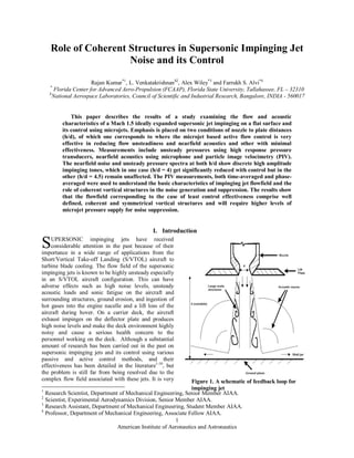
The impinging jet flow field is a highly resonant flow field governed by a well known feedback loop1-12 (Fig. 1).
The concept of the feedback loop and its
understanding has its roots in the pioneering
research of Powell, who explains the feedback
loop associated with edge tones generated by
high speed jets. A number of the general
features of the feedback loop associated with
impinging tones are similar to that elucidated
by Powell4 for edge tones. In a similar manner,
as noted by Tam and Ahuja5 and detailed by
Krothapalli et al.6, the feedback loop in the
impinging jet is initiated as instability waves in
the shear layer of the jet at the nozzle lip. These
instability waves grow in size into large-scale
vortical structures as the jet travels downstream.
In the case of impinging jets, the ground plane
acts as a physical obstruction similar to the
“edges” in edge tones. Upon impingement,
these vortices generate large pressure
fluctuations, which in turn travel upstream in
the ambient flow in the form of acoustic waves. Figure 2. Effectiveness of microjet control, NPR = 3.7
Upon reaching the nozzle exit, these acoustic
waves excite the shear layer and complete the feedback loop. Most of the control systems studied so far including
high momentum microjet control have tried to suppress this feedback loop and seem to work efficiently over a
limited range of geometrical and flow conditions. In particular, effectiveness of microjet control in reducing noise
shows a strong dependence on the nozzle-to-plate distance, nozzle pressure ratio and temperature ratio of the
impinging jet. Figure 2 (data taken from Ref. 11) shows the variation of effectiveness of microjet control (in terms
of reduction in overall sound pressure levels, ∆OASPL) with nozzle-to-plate distance. The results clearly show that
at certain values of h/d, microjet control is very effective in reducing OASPL (e.g., at h/d = 3.5, ∆OASPL = ~12 dB
for lift plate sensor), whereas that is not the case at other values of h/d (e.g., at h/d = 4.5, ∆OASPL = ~3 dB). These
results hence pose a number of questions such as why the control technique which is so effective at some test
condition is not so effective at other test condition. Do the flow features of jet change drastically with a small change
in nozzle-to-plate distance? Does the strength of the feedback loop or evolution of large scale structures vary with
h/d? It is very important to answer these questions to design a robust and highly effective control technique to
mitigate high noise levels associated with supersonic impinging jets. In this study we have taken a closer look at
these results and have made an attempt to answer some of these questions. In addition we have made phase locked
particle image velocimetry measurements at two values of h/d, one corresponding to the case where microjet control
is very effective and the other where it is not so.
II. Experimental Setup
A. Test facility
The experiments were carried out at the STOVL
supersonic jet facility of the Advanced Aero-Propulsion
Laboratory (AAPL) located at the Florida State University.
This facility is mainly used to study jet-induced phenomenon
on STOVL aircraft during hover. It is capable of running
single and multiple jets at design or off-design conditions up
to M = 2.2. In order to simulate different aircraft to ground
plane distances, the ground plate is mounted on a hydraulic
lift and can be moved up and down. A high pressure
compressed air (~160 bars) is stored in large storage tanks
2 Figure 3. A photograph of the STOVL facility
American Institute of Aeronautics and Astronautics
3. (10 m3) and is used to drive the facility. The measurements were made at both design and off-design conditions of
Mach 1.5 jet issuing from a converging-diverging axisymmetric nozzle. The design Mach number of the nozzle was
1.5 and was operated at Nozzle Pressure ratio (NPR, where NPR = stagnation pressure/ambient pressure) of 3.7,
corresponding to ideally expanded jet condition. The test Reynolds number based on exit velocity and nozzle
diameter of the jet was 7 x 10⁵. For these experiments, the stagnation temperature of the jet was kept constant at
300K, corresponding to a temperature ratio, TR =1.0 (where, TR = stagnation temperature / ambient temperature).
The throat and exit diameters (d, de) of the nozzle are 2.54 cm and 2.75 cm respectively. The diverging section of the
nozzle is a straight-walled with 3° divergence angle from the throat to the nozzle exit. A circular plate of diameter
25.4 cm (= 10d) was flush mounted with the nozzle exit. This plate, henceforth referred as lift plate, represents a
generic aircraft planform and has a central hole, equal to the nozzle exit diameter, through which the jet is issued. A
total of sixteen microjets were flush mounted circumferentially on the lift plate around the main jet to implement the
active flow control. The jets are issued using 400 µm diameter stainless steel tubes mounted at an inclination of 60°
with respect to the main jet axis. The supply for the microjets was provided from compressed nitrogen cylinder
through a plenum chamber. The microjets were operated at a pressure of 100 psia and the combined mass flux from
all the microjets was less than 0.5% of the primary jet mass flux.
B. Unsteady pressure and near-field noise measurements
Unsteady pressure measurements on the lift plate were obtained using high frequency response, miniature (1.6
mm dia.) KuliteTM pressure transducers of ±5 psid range mounted at two locations at x/d = 2 and 3 from the nozzle
centerline. Near field acoustic measurements were made using a 0.635 cm (1/4”) diameter B&K microphone placed
at x/d = 15 from the nozzle centerline, 90° with respect to the jet axis. The pressure transducers and microphone
were carefully calibrated prior to each set of experiments. The pressure and acoustic signals were acquired through
high speed National Instruments digital data acquisition cards using LabviewTM and were processed offline. The
transducer signals were conditioned using StanfordTM filters (Model No. SR650) and simultaneously sampled at 70
kHz. Standard FFT analysis was used to obtain spectra and overall Sound Pressure Levels (OASPL) from these
measurements. A total of 100 FFT’s of 4096 samples each were averaged in order to obtain statistically reliable
estimate of the narrow-band spectra.
C. Phase-locked PIV
Flow field measurements using phase locked Particle Image Velocimetry (PIV) were made for few chosen test
conditions. For PIV measurements, a dual cavity digitally sequenced Nd:YAG laser (Spectra Physics PIV400) was
used. A light sheet of approximately 1 mm thickness was created by suitable combination of spherical and
cylindrical lenses and was made to pass through the centerline of the jet. The PIV images were acquired at a rate of
15 Hz using a CCD camera (Kodak ES1.0) with a resolution of 1008 (H) x 1018(V) pixels, where each pixel size is
9 x 9 µm2. The camera was positioned at 90 deg to the jet axis. The pulse separation between the two laser pulses
was kept at 1–1.2 µs. In the present experiments, the jet was seeded with sub-micron (~0.3 µm) Fog fluid (a solution
of glycol and water) droplets generated by a modified Wright nebulizer, which supplied the particles to the main jet.
The ambient air was seeded by a ROSCO 1600 fog generator. An image-matching approach for digital processing,
similar to that used in previous experiments at AAPL (Krothapalli et al. [7] and Alvi et al. [19]), was used to extract
particle displacement and the velocity field. In this processing scheme, the interrogation window is defined by the
particle displacements , ranging from 3 to 4 pixels and the interrogation window used in the present study was
nominally set to 20 x 20 pixels. However, the adaptive scheme used in the processing ensured that a minimum of 10
pairs of particle images were matched in each interrogation cell by resizing the interrogation window as required.
The data was processed on a N x M points regularly spaced mesh. (PLEASE INSERT N AND M HERE) The
flowfield at every point is calculated using a least-square fitting algorithm based on a second-order polynomial. This
technique results in a second-order accuracy in calculating the flowfield at each point in the flow. The details of this
technique are available in Lourenco and Krothapalli [21]. The near field microphone signal was used for
the purposes of phase-locking PIV measurements. Figure 4 shows a schematic of the phase-locking setup. The raw
signal from the microphone was first recorded unfiltered and processed online using LabVIEW® codes (same FFT
parameters as in the previous section). Thereafter the signal was narrowly band-pass filtered around the impinging
tone as measured from the spectra using a Stanford Research Systems SR650 High Pass/Low Pass filter. The signal
was then sent to a Model 88 Laser Lock made by Hendrick and Associates. This signal was divided such that it
corresponded to the frequency of the laser and the camera. The signal was then fed into custom timing hub matched
to a National Instruments® PCI-6602 timing card and an IMAQ 1422 image acquisition card. Phase-delays in the
trigger signal to the laser/camera were included using proVISION-XS software from IDT® which was also used to
acquire and process the images. Finally, a delay on the divided signal was applied to generate the necessary phase
3
American Institute of Aeronautics and Astronautics
4. trigger for the synchronized camera and laser strobe. The laser frequency of 15 Hz requires the pulsation frequency
to be a multiple of 15. The full cycle of a pulse was sampled in 12 phases with equal intervals. At every phase, 300
image pairs were obtained. Phase-averaged velocity fields were computed by taking the mean of these instantaneous
fields. The measurement uncertainty is estimated to be about 1% and 10% in phased-averaged velocity and random
turbulence measurements, respectively, with a 95% confidence level. The global mean quantities were calculated
from phase-averaged values.
Figure 4. Schematic of the Phase-Locking System
III. Results and Discussion
As stated in the introduction section, the main objective of this study is to understand the basic characteristics of
the supersonic impinging jets with and without microjet control. Unsteady pressures, near-field noise and phase
locked PIV measurements were made with jet operating at NPR = 3.7 for two values of nozzle-to-plate distance h/d,
4 and 4.5. Measurements were carried out both with and without microjet control operating at a fixed pressure
supply of 100 psia.
A. Unsteady Pressures and Near-field Noise
Figure 5 shows the near-field noise spectra measured using microphone located at 15d from the nozzle exit. The
4
Figure 5. Near-field noise spectra obtained using microphone located at 15d from centerline in the nozzle exit
American Institute of Aeronautics and Astronautics
plane. (a) h/d = 4, (b) h/d = 4.5
5. figure includes the data obtained at two values of h/d, 4 and 4.5 with and without control. As stated earlier, h/d = 4 is
the case where microjet control was found to be very effective in reducing the noise levels and h/d = 4.5 is the case
corresponding to minimal effect of control. As clearly seen in Fig. 5a, at h/d = 4; the spectra without control consist
of a sharp impinging tone (5.8 kHz) along with its harmonics and high broadband levels. With microjet control, the
amplitude of dominant impinging tone is significantly reduced (nearly 22 dB) along with a reduction in broadband
levels. At h/d = 4.5, the baseline (without control) spectra shows multiple discrete impinging tones (2.8kHz, 4.1kHz,
6.5kHz, 9.3kHz) and their harmonics and the broadband levels are even higher than those at h/d = 4. Also, it is to be
observed that at h/d = 4, the spectra shows a continuous decrease in SPL with frequency beyond 10kHz except
couple of low amplitude harmonics of impinging tone, whereas, at h/d = 4.5 the SPLs continue to be high even at
higher frequencies (beyond 10 kHz). This behavior at high frequencies can be attributed to the broadband
amplification that normally occurs when strong tones are present in the spectra. With microjet control at h/d = 4.5,
there is no reduction in the dominant impinging tone and its harmonics and a marginal reduction in broadband
levels, however, most of the other tones present in the baseline spectra are eliminated.
Figure 6. Narrowband pressure spectra at the lift plate; (a) h/d = 4, (b) h/d = 4.5
The narrowband pressure spectra for the two values of h/d, 4 and 4.5, measured at the lift plate is shown in Fig.
6. The features of pressure spectra at both h/d values without control are very similar showing multiple high
amplitude impinging tones and their harmonics. The frequencies of impinging tones observed in the lift plate spectra
are identical to that of near-field microphone spectra indicating a global nature of the noise producing mechanisms.
With microjet control at h/d = 4, the amplitude of all the tones is significantly reduced (a maximum of 32 dB
reduction along with a major reduction in broadband levels, whereas at h/d = 4.5, the dominant impinging tone and
its harmonics remain virtually unaffected. The kulite pressure sensor mounted in the lift plate is very sensitive and
seems to pickup even minor vibrations in the plate. These results clearly demonstrate that the baseline (without
control) pressure spectra at the lift plate and the spectra of near-field noise at the two values of h/d show few
identical and some different features. Also, the effect of microjet control in reducing pressure unsteadiness and near-
field noise at two h/d is very different.
B. Mean velocity field
Global information regarding the evolution of the impinging jet flowfield and velocity field along a streamwise
central plane was obtained using PIV. PIV measurements were made at both values of h/d, 4 and 4.5 with and
without microjet control. The mean velocity field for the baseline flow corresponding to h/d = 4 and 4.5 is shown in
Fig. 7. The results are presented in the form of contour plots of the ensemble-averaged (mean) streamwise velocity
(u) normalized with fully expanded jet velocity (Ujet). Velocity vectors at selected locations and the streamlines in
the ambient and in the shear layer of the jet are shown superposed on the mean velocity contour plots. As mentioned
earlier, measurements were made at NPR =3.7, corresponding to ideally expanded jet conditions. However, a weak
periodic shock cell structure can be observed in both the cases. This may be due to weak shocks generated by the
nozzle lip and a significant entrainment of ambient air resulting in a mildly under-expanded jet. The velocity vectors
5
American Institute of Aeronautics and Astronautics
6. a) h/d = 4 b) h/d = 4.5
Figure 7. Mean velocity distribution in the central plane of the impinging jet.
close to the nozzle exit show top-hat velocity profile in both cases. The streamlines exhibit flow entrainment into the
shear layer of the jet as it flows downward and formation of the wall jet at the impingement plate. In general, the
global flow features of the impinging jet flowfield is very similar at h/d = 4 and 4.5 and doesn’t show any
considerable change between the two cases. With microjet control (not shown here), the velocity flowfield was
nearly the same suggesting that most of the mean flow properties of the jet remain unaltered with control. These
a) h/d = 4 b) h/d = 4.5
Figure 8. Mean vorticity distribution in the central plane of the impinging jet.
features are very similar to those observed in earlier studies.
The impinging jet flowfield is known to be highly resonant and associated with instability waves in the shear
layer which grow into large-scale vortical structures, so it is important to analyze the vorticity field associated with
impinging jets. The ensemble-averaged vorticity contour plots measured along the jet central plane for h/d =4 and
4.5 are shown in Fig. 8. The contours show the azimuthal component of the normalized vorticity, Zdj/Ujet, where dj
is the diameter of the nozzle at throat and Ujet is the fully expanded jet velocity at Mach 1.5. Compared to h/d = 4,
the vorticity levels for h/d = 4.5 are higher and the size of the vortex structures seems to be bigger. Although the
Figs.7 and 8 show the global flowfield of the impinging jet at two h/d, we need to further investigate to get better
understanding of the associated flow physics.
6
American Institute of Aeronautics and Astronautics
7. a) ϕ = 0º b) ϕ = 60º
c) ϕ = 120º d) ϕ = 180º
e) ϕ = 240º f) ϕ = 300º
Figure 9. Phase-averaged impinging jet flowfield at h/d = 4.5; Left hand side: azimuthal vorticity; Right
hand side: streamwise velocity in the center plane.
7
American Institute of Aeronautics and Astronautics
8. C. Phase locked velocity field
In order to better understand the flow physics associated with impinging jets with and without control at the two
values of h/d, phase locked velocity measurements were carried out using PIV. The phase averaged flowfield
enables the construction of time evolution of different flow properties. The near field microphone signal was used
for the purposes of phase-locking. As seen earlier in Fig. 4, at h/d=4 there is a single sharp tone at 5.8 kHz and we
used this tone to phase-lock PIV at this h/d. A total of 300 image pairs were captured at every 30° resulting in 13
datasets at 12 phases (0° and 360° overlap). At h/d = 4.5, there were four distinct tones in the spectra at 2.8, 4.1, 6.5
and 9.3 kHz, the dominant of which being at 6.5 kHz. While phase-locked PIV was performed at 4.1, 6.5 and 9.5
kHz, only the data collected at the strongest tone of 6.5
kHz will be discussed in this paper. Figure 9 shows the
contour plots of the phase averaged streamwise velocity
and azimuthal vorticity at h/d 4.5. The figure includes
equally spaced (60º apart) six phase angles. The
streamwise velocity and azimuthal vorticity contours are
shown on right and left hand side of each plot. The
vorticity level flood lines and flow streamlines are
superposed as well. These figures demonstrate some of
the salient features of impinging jet flow field at h/d =
4.5. The figures clearly show the presence of multiple
well defined vortical structures in the shear layer at each
phase. The instability initiates at the nozzle exit, grows
into a large scale vortex which convects downstream
and eventually after impingement on the ground moves
along the wall jet. As these vortices roll down and create
a local suction, there is a significant entrainment of the
ambient air into the shear layer of the jet which leads to
the spreading of the jet. It is interesting to observe from
the vorticity contours that the vorticity in the shear layer Figure 10. Phase-averaged impinging jet flowfield
is negative (clockwise rotation) whereas in the wall jet it at h/d = 4, ϕ = 0º
is positive (counterclockwise rotation) and there is an
iso-surface close to the impingement surface where the vorticity is zero
Similar to Fig. 9a for h/d = 4.5 and ϕ = 0º, the phase averaged contour plots of streamwise velocity and out-of-
plane vorticity for h/d = 4 and ϕ = 0º is shown in Fig. 10. In comparison to h/d = 4.5, the contour plots for h/d = 4
show relatively less coherent and weaker structures in the shear layer and the vorticity level in the shear layer is
relatively less for h/d = 4.
To calculate the number, size, strength and other parameters associated with vortices, one has to precisely
identify the location of these vortices in the flowfield. There are a number of techniques that have been used in the
literature to extract the vortices from the associated velocity and vorticity field. The simple one being using surfaces
of constant vorticity magnitude (Figs. 9 and 10) but it does not differentiate between the shear and vortical motion.
Other complex techniques involve the analysis of the local velocity gradient tensor and calculation of eigen values.
To identify the vortical structures in the shear layer of the impinging jet, we have calculated the parameter “Swirling
డ௨భ డ௨భ
Strength” as described by Adrian et al. (2000). The velocity gradient tensor in the central plane is given by
డ௫ డ௫మ
CAN WE PUT A SYMBOL FOR VEL GRAD TENSOR HERE?? డ௨భ డ௨మ
మ
డ௫భ డ௫మ
8
American Institute of Aeronautics and Astronautics
9. where the subscripts 1 and 2 correspond to streamwise and cross-stream directions respectively. Identification of
vortical structures is done by plotting regions where the imaginary portion of the complex eigen value is positive,
b) h/d = 4 b) h/d = 4.5
Figure 11. Swirl strength distribution in the central plane of the impinging jet, ϕ = 0º.
i.e. λci>0. The swirl-Strength is then the magnitude of this parameter. Figure 11 shows the contour plots of swirl
strength for h/d = 4 and 4.5 at ϕ = 0º. The swirl strength analysis clearly brings out the differences between the two
flowfields. Compared to h/d = 4, there are three pairs of coherent, well defined and symmetrical vortical structures at
h/d = 4.5. The magnitude of the swirl strength for the vortices for h/d = 4.5 is much higher than at h/d = 4, indicating
that the vortices are much stronger in the former case.
As mentioned in the experimental setup section, the active control involved sixteen equally spaced 400 µm microjets
around the periphery of the jet operating at a pressure of 100 psia. The effect of microjet control on the swirl
strength at h/d = 4 and 4.5 is shown in Fig. 12. At h/d = 4, the coherence of vortices is completely broken with
control and one observes a number of small scale structures instead of well defined equal pairs of large structures.
However, at h/d = 4.5 with microjet control the strength of vortices is relatively reduced but the cohesiveness is still
maintained. The shape of vortices near the nozzle exit is somewhat disturbed but as the flow moves downstream,
9
American Institute of Aeronautics and Astronautics
a) h/d = 4 b) h/d = 4.5
Figure 12. Effect of control on swirl strength distribution, ϕ = 0º.
10. those roll up and become once again coherent. The outcome of the flowfield results with control agrees with those of
acoustic measurements. These results clearly suggest that there is a need to further increase the strength of microjet
control by increasing the supply pressure, so that microjets penetrate deep into the shear layer and break the
coherence of these large scale structures.
IV. Conclusions
The understanding of the flow physics associated with supersonic impinging jets is of great importance for the
design of a robust control technique to suppress the high levels of noise associated with these jets. Previous studies
indicate that the effectiveness of microjet based control has a strong dependence on the nozzle-to-plate distance, so
we chose two values of this parameter of unequal effectiveness in this study. The experimental results described in
this paper include unsteady pressures, nearfield acoustics, and velocity and vorticity fields. Pressure and noise
spectra showed the presence of multiple, high amplitude, discrete impinging tones along with high broadband levels.
Time averaged velocity and vorticity measurement provided the whole field data and indicated different levels of
vorticity for the two flowfields but it did not provide enough information on the role of vortices. Phase-averaged
velocity and vorticity measurements brought out clear differences between the two flowfields, the difference in the
strength and size of vortices in the shear layer. The swirl strength levels further elucidated on the vortex statistics of
the two cases and the effect of control in weakening those vortical structures.
Acknowledgments
We would like to thank the Florida Center for Advanced Aero-propulsion (FCAAP), a statewide center of
excellence for supporting this research.
References
[1] Donaldson, C. DuP and Snedeker, R. S., “A study of free jet impingement. Part 1. Mean properties of free and impinging
jets,” Journal of Fluid Mechanics, Vol. 45, No. 2, 1971, pp. 281–319.
[2] Lamont, P. J. and Hunt, B. L., “The impingement of underexpanded axisymmetric jets on perpendicular and inclined flat
plates,” Journal of Fluid Mechanics, Vol. 100, 1980, pp. 471–511.
[3] Powell, A., “The sound-producing oscillations of round underexpanded jets impinging on normal plates”, Journal of Acoustic
Society of America, Vol. 83, 1988, pp. 515–533.
[4] Tam, C. K. W. and Ahuja, K. K., “Theoretical model of discrete tone generation by impinging jets”, Journal of Fluid
Mechanics, Vol. 214, 1990, pp. 67–87.
[5] Messersmith, N. L., “Aeroacustics of supersonic and impinging jets”, AIAA paper 95–0509, 1995.
[6] Alvi, F. S. and Iyer, K. G., “Mean and unsteady flow field properties of supersonic impinging jets with lift plates,” AIAA
Paper 99–1829, 1999.
[7] Krothapalli, A., Rajkuperan, E., Alvi, F. S. and Lourenco, L., “Flow field and noise characteristics of a supersonic impinging
jet,” Journal of Fluid Mechanics, Vol. 392, 1999, pp. 155–181.
[8] Henderson, B., Bridges, J. and Wernet, M., “An experimental study of the oscillatory flow structure of tone producing
supersonic impinging jets,” Journal of Fluid Mechanics, Vol. 542, 2005, pp. 115–137.
[9] Powell, A., “On edge tones and associated phenomena,” Acoustica, Vol. 3, 1953, pp.233–243.
[10] Karamcheti, K., Bauer, A. B., Shields, W. L. Stegen, G. R. and Woolley, J. P., “Some features of an edge tone flow field,”
NASA SP 207, 1969, pp. 275–304.
10
American Institute of Aeronautics and Astronautics
11. [11] Kweon, Y. –H., Miyazato, Y., Aoki, T., Kim, H. –D. and Setoguchi, T., “Control of supersonic jet noise using a wire device,”
Journal of Sound and Vibrations, Vol. 297, 2006, pp. 167–182.
[12] Elavarasan, R., Krothapalli, A., Venkatakrishnan, L. and Lourenco, L., “Suppression of self-sustained oscillations in a
supersonic impinging jet”, AIAA Journal, Vol. 39, No. 12, 2001, pp. 2366–2373.
[13] Sheplak, M. and Spina, E. F., “Control of high speed impinging-jet resonance”, AIAA Journal, Vol. 32, No. 8, 1994,
pp.1583–1588.
[14] Shih, C., Alvi, F. S. and Washington, D., “Effects of counterflow on the aeroacustic properties of a supersonic jet,” Journal
of Aircraft, Vol. 36, No. 2, 1999, pp. 451–457.
[15] Alvi, F. S., Shih, C., Elavarasan, R., Garg, G. and Krothapalli, A., “Control of supersonic impinging jet flows using
supersonic microjets,” AIAA Journal, Vol. 41, No. 7, 2003, pp. 1347–1355.
[16] Lou, H., Shih, C. and Alvi, F. S., “A PIV study of supersonic impinging jet,” AIAA Paper 2003–3263, 2003.
[17] Lou, H., Alvi, F. S. and Shih, C., “Active and adaptive control of supersonic impinging jets,” AIAA Journal, Vol. 44, No. 1,
2006, pp. 58–66.
[18] Kumar, R., Lazic, S., and Alvi, F. S., “Active control of high temperature supersonic impinging jets,” AIAA Paper 2008–360,
2008.
[19] Alvi, F. S., Lou, H., Shih, C., and Kumar, R., “Experimental study of physical mechanisms in the control of supersonic
impinging jets using microjets,” Journal of Fluid Mechanics, Vol. 613, 2008, pp. 55–83.
[20] Alkislar, M. B., Krothapalli, A., and Butler, G. W., “The effect of streamwise vortices on the aeroacoustics of a Mach 0.9
jet,” Journal of Fluid Mechanics, Vol. 578, 2007, pp. 139–169.
11
American Institute of Aeronautics and Astronautics