Ru series (1)
•
0 likes•219 views

The document provides information on Omron's RU Series universal relays, including: - The RU Series includes plug-in and PCB mount relays with DPDT, 4PDT, and 4PDT bifurcated contact configurations. - Features include LED indicators, mechanical flag indicators, latching levers, and marking plates for terminal identification. - Relays are available with AC or DC coils in various voltage ratings and with surge protection components. - Contact ratings vary by model with maximum ratings of 10A for DPDT and 6A for 4PDT configurations. - Specifications include electrical life, operating temperature range, vibration resistance, and more.

Recommended
More Related Content
What's hot
What's hot (14)
Similar to Ru series (1)
Similar to Ru series (1) (20)
Recently uploaded
Recently uploaded (20)
Ru series (1)
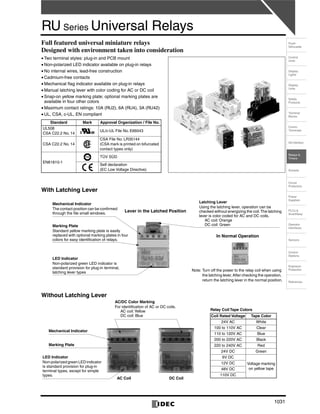
- 1. 1031 Control Units Display Lights Display Units Safety Products Terminal Blocks Comm. Terminals AS-Interface Relays & Timers Sockets Circuit Protectors Power Supplies PLCs & SmartRelay Operator Interfaces Sensors Control Stations Explosion Protection References Flush Silhouette RU Series Universal Relays Full featured universal miniature relays Designed with environment taken into consideration • Two terminal styles: plug-in and PCB mount • Non-polarized LED indicator available on plug-in relays • No internal wires, lead-free construction • Cadmium-free contacts • Mechanical flag indicator available on plug-in relays • Manual latching lever with color coding for AC or DC coil • Snap-on yellow marking plate; optional marking plates are available in four other colors • Maximum contact ratings: 10A (RU2), 6A (RU4), 3A (RU42) • UL, CSA, c-UL, EN compliant With Latching Lever Without Latching Lever Standard Mark Approval Organization / File No. UL508 CSA C22.2 No. 14 UL/c-UL File No. E66043 CSA C22.2 No. 14 CSA File No. LR35144 (CSA mark is printed on bifurcated contact types only) EN61810-1 TÜV SÜD Self declaration (EC Low Voltage Directive) Lever in the Latched Position Mechanical Indicator The contact position can be confirmed through the file small windows. Marking Plate Standard yellow marking plate is easily replaced with optional marking plates in four colors for easy identification of relays. LED Indicator Non-polarized green LED indicator is standard provision for plug-in terminal, latching lever types Latching Lever Using the latching lever, operation can be checked without energizing the coil.The latching lever is color coded for AC and DC coils. AC coil: Orange DC coil: Green In Normal Operation Note: Turn off the power to the relay coil when using the latching lever.After checking the operation, return the latching lever in the normal position. AC/DC Color Marking For identification of AC or DC coils. AC coil:Yellow DC coil: Blue Mechanical Indicator Marking Plate LED Indicator Non-polarized green LED indicator is standard provision for plug-in terminal types, except for simple types. AC Coil DC Coil Relay Coil Tape Colors Coil Rated Voltage Tape Color 24V AC White 100 to 110V AC Clear 110 to 120V AC Blue 200 to 220V AC Black 220 to 240V AC Red 24V DC Green 6V DC Voltage marking on yellow tape 12V DC 48V DC 110V DC
- 3. RU Series Universal Relays 1032 Types •••• Single Contact Type •••• Bifurcated Contact Type Note 1: Plug-in terminal types, except for simple types, have an LED indicator and a mechanical indicator as standard. Note 2: Simple types do not have an LED indicator, a mechanical indicator, and a latching lever. Ordering Information Specify a coil voltage code in place of ∗ in the Type No. Accessory Note: Specify a color code in place of the Type No. When ordering, specify the Ordering Type No. The marking plate can be removed from the relay by inserting a flat screwdriver under the marking plate. Termination Latching Lever Type Type No. Coil Voltage Code ∗ DPDT 4PDT Plug-in Terminal (Note 1) With Latching Lever Standard RU2S-∗ RU4S-∗ A24, A100, A110, A200, A220 D6, D12, D24, D48, D110 With RC (AC coil only) RU2S-R-∗ RU4S-R-∗ A100, A110, A200, A220 With diode (DC coil only) RU2S-D-∗ RU4S-D-∗ D6, D12, D24, D48, D110 With diode (DC coil only) Reverse polarity coil RU2S-D1-∗ RU4S-D1-∗ D24 Without Latching Lever Standard RU2S-C-∗ RU4S-C-∗ A24, A100, A110, A200, A220 D6, D12, D24, D48, D110 With RC (AC coil only) RU2S-CR-∗ RU4S-CR-∗ A100, A110, A200, A220 With diode (DC coil only) RU2S-CD-∗ RU4S-CD-∗ D6, D12, D24, D48, D110 With diode (DC coil only) Reverse polarity coil RU2S-CD1-∗ RU4S-CD1-∗ D24 Simple (Note 2) RU2S-NF-∗ RU4S-NF-∗ A24, A100, A110, A200, A220 D6, D12, D24, D48, D110PCB Terminal Without Latching Lever Simple (Note 2) RU2V-NF-∗ RU4V-NF-∗ Termination Latching Lever Type Type No. 4PDT Coil Voltage Code ∗ Plug-in Terminal (Note 1) With Latching Lever Standard RU42S-∗ A24, A100, A110, A200, A220 D6, D12, D24, D48, D100, D110 With RC (AC coil only) RU42S-R-∗ A100, A110, A200, A220 With diode (DC coil only) RU42S-D-∗ D6, D12, D24, D48, D100, D110 With diode (DC coil only) Reverse polarity coil RU42S-D1-∗ D24 Without Latching Lever Standard RU42S-C-∗ A24, A100, A110, A200, A220 D6, D12, D24, D48, D100, D110 With RC (AC coil only) RU42S-CR-∗ A100, A110, A200, A220 With diode (DC coil only) RU42S-CD-∗ D6, D12, D24, D48, D100, D110 With diode (DC coil only) Reverse polarity coil RU42S-CD1-∗ D24 Simple (Note 2) RU42S-NF-∗ A24, A100, A110, A200, A220 D6, D12, D24, D48, D100, D110PCB Terminal Without Latching Lever Simple (Note 2) RU42V-NF-∗ Coil Voltage Code ∗ Coil Rating A24 24V AC A100 100-110V AC A110 110-120V AC A200 200-220V AC A220 220-240V AC D6 6V DC D12 12V DC D24 24V DC D48 48V DC D100 100V DC D110 110V DC Name Type No. Ordering Type No. Color Code ∗ Package Quantity Marking Plate RU9Z-P∗ RU9Z-P∗PN10 A (orange), G (green), S (blue), W (white), Y (yellow) 10
- 4. RU Series Universal Relays 1033 Control Units Display Lights Display Units Safety Products Terminal Blocks Comm. Terminals AS-Interface Relays & Timers Sockets Circuit Protectors Power Supplies PLCs & SmartRelay Operator Interfaces Sensors Control Stations Explosion Protection References Flush Silhouette Coil Ratings Note 1: The rated current includes the current draw by the LED indicator. Note 2: Rated voltage 100V DC is available for the bifurcated contact type only. Rated Voltage (V) Coil Voltage Code Rated Current (mA) ±15% (at 20°C) Coil Resistance (Ω) ±10% (at 20°C) Operating Characteristics (against rated values at 20°C) Maximum Continuous Applied Voltage Minimum Pickup Voltage Dropout Voltage 50 Hz 60 Hz AC (50/60 Hz) 24 A24 49.3 42.5 164 110% 80% maximum 30% minimum 100-110 A100 9.2-11.0 7.8-9.0 3,460 110-120 A110 8.4-10.0 7.1-8.2 4,550 200-220 A200 4.6-5.5 4.0-4.6 14,080 220-240 A220 4.2-5.0 3.6-4.2 18,230 DC 6 D6 155 40 110% 80% maximum 10% minimum 12 D12 80 160 24 D24 44.7 605 48 D48 18 2,560 100 D100 9.7 10,000 110 D110 8.9 12,100 Contact Ratings Note 1: On 4PDT relays, the maximum allowable total current of neighboring two poles is 6A. At the rated load, make sure that the total current of neighboring two poles does not exceed 6A (3A + 3A = 6A). Note 2: Inductive load for the rated load — cos ø = 0.3, L/R = 7 ms •••• UL and c-UL Ratings •••• CSA Ratings •••• TÜV Ratings Surge Suppressor Ratings Specifications Note: Above values are initial values. ∗1: Measured using 5V DC, 1A voltage drop method ∗2: Measured at operating frequency of 120 operations/min (failure rate level P, reference value) ∗3: Measured at the rated voltage (at 20°C), excluding contact bouncing; Release time of AC relays with RC: 25 ms maximum Release time of DC relays with diode: 40 ms maximum ∗4: Contact Load and Electrical Life (at ambient temperature 20°C) ∗5: Measured at the rated voltage. Simple types include plug-in terminal sim- ple types and all PCB terminal types. Contact Continu- ous Current Allowable Contact Power Voltage (V) Rated Load Res. Load Ind. Load Resistive Load Inductive Load DPDT 10A 2500VA AC 300W DC 1250VA AC 150W DC 250 AC 10A 5A 30 DC 10A 5A 4PDT 6A 1500VA AC 180W DC 600VA AC 90W DC 250 AC 3A 0.8A 30 DC 3A 1.5A 4PDT bifurcated 3A 750VA AC 90W DC 200VA AC 45W DC 250 AC 3A 0.8A 30 DC 3A 1.5A Voltage Resistive General Use Horse Power Rating RU2 RU4 RU42 RU2 RU4 RU42 RU2 RU4 RU42 250V AC 10A — 3A — 6A — — 1/10HP — 30V DC 10A 6A 3A — — — — — — Voltage Resistive RU42 250V AC 3A 30V DC 3A Voltage Resistive Inductive RU2 RU4 RU42 RU2 RU4 RU42 250V AC 10A 6A 3A 5A 0.8A 0.8A 30V DC 10A 6A 3A 5A 1.5A 1.5A Type Ratings AC Coil With RC RC series circuit R: 20 kΩ, C: 0.033 μF DC Coil With Diode Diode reverse voltage: 1000V Diode forward current: 1A Type (Contact) RU2 (DPDT) RU4 (4PDT) RU42 (4PDT) Contact Material Silver alloy Silver (gold clad) Silver-nickel (gold clad) Contact Resistance ∗1 50 mΩ maximum Minimum Applicable Load ∗2 24V DC, 5 mA 1V DC, 1 mA 1V DC, 0.1 mA (reference value) Operate Time ∗3 20 ms maximum Release Time ∗3 20 ms maximum Power Consumption AC: 1.1 to 1.4VA (50 Hz), 0.9 to 1.2VA (60 Hz) DC: 0.9 to 1.0W Insulation Resistance 100 MΩ minimum (500V DC megger) Dielectric Strength Between contact and coil: 2500V AC, 1 minute Between contacts of different poles: 2500V AC, 1 minute 2000V AC, 1 minute Between contacts of the same pole: 1000V AC, 1 minute Operating Frequency Electrical: 1800 operations/h maximum Mechanical: 18,000 operations/h maximum Vibration Resistance Damage limits: 10 to 55 Hz, amplitude 0.5 mm Operating extremes: 10 to 55 Hz, amplitude 0.5 mm Shock Resistance Damage limits: 1000 m/s2 Operating extremes: 150 m/s2 Mechanical Life AC: 50,000,000 operations DC: 100,000,000 operations 50,000,000 operations Electrical Life ∗4 See table below Operating Temperature ∗5 Simple types: –55 to +70°C (no freezing) Others: –55 to +60°C (no freezing) Operating Humidity 5 to 85% RH (no condensation) Weight Approx. 35g Type Voltage Resistive Load Inductive Load (cos ø = 0.3, L/R = 7 ms) Electrical Life (operations minimum) RU2 250V AC 10A 5A 100,000 5A 2.5A 500,000 30V DC 10A 5A 100,000 5A 2.5A 500,000 110V DC 0.6A 0.4A 100,000 RU4 250V AC 6 2.6A 50,000 3A 0.8A 200,000 30V DC 6A 2.7A 50,000 3A 1.5A 200,000 110V DC 0.65A 0.33A 50,000 0.33A 0.18A 200,000 RU42 250V AC 3A 0.8A 100,000 30V DC 3A 1.5A 100,000 110V DC 0.44A 0.22A 100,000
- 5. RU Series Universal Relays 1034 Dimensions Internal Connection (Bottom View) RU2 (DPDT Contact) •••• Plug-in Terminal Type •••• PCB Terminal Type • LED indicator, mechanical flag indica- tor, and marking plate are standard provisions, except on simple types. • Available with or without a manual latching lever • Simple types have a marking plate. • Marking plate is a standard provi- sion. • Not provided with an LED indica- tor, mechanical flag indicator, and manual latching lever. Photo: RU2S-A100 Photo: RU2V-NF-A100 Latching Lever AC: Orange DC: Green Marking Plate (yellow) ø1.2 × 2.2 Hole LED Indicator (green) 35.06.4 2.60.5 27.5 21.0 14 58 912 1314 8-ø1 Holes 27.5 12.74.1 6.4 7.0 13.2 0.8 13.2 2.6 4.0 0.5 21.0 0.5 35.0Mounting Hole Layout Marking Plate (yellow) Marking Plate Removal Slot Color Marking AC: Yellow DC: Blue 27.5 Marking Plate Removal Slot Color Marking AC: Yellow DC: Blue 14 58 912 1314 35.06.4 2.6 0.5 21.0 ø1.2 × 2.2 Hole LED Indicator (green) (RU2S-C only) Mechanical Indicator Window (RU2S-C only) Marking Plate (yellow) •••• RU2S •••• RU2S-C/RU2S-NF •••• RU2V Marking plate removal slot is provided only on one side. Insert a flat screwdriver into the slot to remove the marking plate. All dimensions in mm. (14)A2(13)A1 (12)41(9)11 (8)44(5)14 (4)42(1)12 Over 24V AC/DC 24V AC/DC or less (13)A1 (14)A2 (1)12 (4)42 (5)14 (8)44 (9)11 (12)41 (14)A2(13)A1 (12)41(9)11 (8)44(5)14 (4)42(1)12 (1)12 (4)42 (5)14 (8)44 (9)11 (12)41 (13)A1 (14)A2 Over 24V DC 24V DC or less (14)A2(13)A1 (12)41(9)11 (8)44(5)14 (4)42(1)12 (14)A2(13)A1 24V DC (12)41(9)11 (8)44(5)14 (4)42(1)12 (14)A2(13)A1 (12)41(9)11 (8)44(5)14 (4)42(1)12 •••• RU2S-∗∗∗∗ Standard •••• RU2S-∗∗∗∗R With RC •••• RU2S-∗∗∗∗D With Diode •••• RU2S-∗∗∗∗D1 With Diode Reverse Polarity Coil •••• RU2S-NF-∗∗∗∗/RU2V-NF-∗∗∗∗ Blank or C comes in place of ∗ to represent types with or without a latching lever.
- 6. RU Series Universal Relays 1035 Control Units Display Lights Display Units Safety Products Terminal Blocks Comm. Terminals AS-Interface Relays & Timers Sockets Circuit Protectors Power Supplies PLCs & SmartRelay Operator Interfaces Sensors Control Stations Explosion Protection References Flush Silhouette Electrical Life Curves Maximum Switching Current Ambient Temperature vs.Temperature Rise Curves 10 1000 100 1 10510.50.1 110V DC 30V DC 250V AC Load Current (A) (×10,000operations) 0.1 0.5 1 5 10 1 100 1000 10 110V DC 250V AC/30V DC Load Current (A) (×10,000operations) DC: L/R = 7 ms AC: cos ø = 0.3 •••• RU2 (Resistive Load) •••• RU2 (Inductive Load) 10 5 0.1 1 10 30 100 250 500 AC resistive AC inductive (cos ø = 0.3) Load Voltage (V) LoadCurrent(A) DC resistive DC inductive L/R = 7 ms •••• RU2 120 110 100 90 80 70 60 50 40 30 20 10 706050403020100 Ambient Temperature (°C) TemperatureRise(°C) Load current 5A × 2 poles Load current 10A × 2 poles No load current 0 10 20 30 40 50 60 70 10 20 30 40 50 60 70 80 90 100 110 120 Ambient Temperature (°C) TemperatureRise(°C) Load current 5A × 2 poles Load current 10A × 2 poles No load current 0 10 20 30 40 50 60 70 10 20 30 40 50 60 70 80 90 100 110 120 Ambient Temperature (°C) TemperatureRise(°C) Load current 5A × 2 poles Load current 10A × 2 poles No load current •••• RU2 (AC Coil, 50 Hz) •••• RU2 (AC Coil, 60 Hz) •••• RU2 (DC Coil) The above temperature rise curves show the characteristics when 100% the rated coil voltage is applied. The heat resistance of the coil is 120°C. The slant dashed line indicates the allowable temperature rise for the coil at different ambient temperatures.
- 7. RU Series Universal Relays 1036 Dimensions Internal Connection (Bottom View) RU4 (4PDT Contact) •••• Plug-in Terminal Type •••• PCB Terminal Type • LED indicator, mechanical flag indica- tor, and marking plate are standard provisions, except on simple types. • Available with or without a manual latching lever • Simple types have a marking plate. • Marking plate is a standard provi- sion. • Not provided with an LED indica- tor, mechanical flag indicator, and manual latching lever. Photo: RU42S-A100 Photo: RU4V-NF-D24 (RU4) (RU42) 3-4.4 0.8 2.6 4.0 0.5 0.5 27.5 21.0 13.27.0 6.4 4.1 12.7 4.435.0 14-ø1 HolesMounting Hole Layout Marking Plate (yellow) Marking Plate Removal Slot Color Marking AC: Yellow DC: Blue •••• RU4S/RU42S •••• RU4S-C/RU4S-NF RU42S-C/RU42S-NF •••• RU4V/RU42V Marking plate removal slot is provided only on one side. Insert a flat screwdriver into the slot to remove the marking plate. All dimensions in mm. 1413 1211109 8765 4321 6.4 21.0 27.5 0.5 2.6 35.0 Latching Lever AC: Orange DC: Green ø1.2 × 2.2 Hole LED Indicator (green) Marking Plate Removal Slot Mechanical Indicator Window Marking Plate (yellow) 6.4 0.5 2.6 35.0 27.5 21.0 Marking Plate Removal Slot Color Marking AC: Yellow DC: Blue ø1.2 × 2.2 Hole LED Indicator (green) (RU4S-C/ RU42S-C only) Marking Plate (yellow) 1413 1211109 8765 4321 Mechanical Indicator Window (RU4S-C/RU42S-C only) (1)12 (2)22 (3)32 (4)42 (5)14 (6)24 (7)34 (8)44 (9)11 (10)21 (11)31 (12)41 (13)A1 (14)A2 Over 24V AC/DC (14)A2(13)A1 (12)41(11)31(10)21(9)11 (8)44(7)34(6)24(5)14 (4)42(3)32(2)22(1)12 24V AC/DC or less (14)A2(13)A1 (12)41(11)31(10)21(9)11 (8)44(7)34(6)24(5)14 (4)42(3)32(2)22(1)12 Over 24V DC (14)A2(13)A1 (12)41(11)31(10)21(9)11 (8)44(7)34(6)24(5)14 (4)42(3)32(2)22(1)12 24V DC or less (14)A2 (1)12 (2)22 (3)32 (4)42 (5)14 (6)24 (7)34 (8)44 (9)11 (10)21 (11)31 (12)41 (13)A1 24V DC (1)12 (2)22 (3)32 (4)42 (5)14 (6)24 (7)34 (8)44 (9)11 (10)21 (11)31 (12)41 (13)A1 (14)A2 (14)A2(13)A1 (12)41(11)31(10)21(9)11 (8)44(7)34(6)24(5)14 (4)42(3)32(2)22(1)12 •••• RU4S-∗∗∗∗/RU42S-∗∗∗∗ Standard •••• RU4S-∗∗∗∗R/RU42S-∗∗∗∗R With RC •••• RU4S-∗∗∗∗D/RU42S-∗∗∗∗D With Diode •••• RU4S-∗∗∗∗D1/RU42S-∗∗∗∗D1 With Diode Reverse Polarity Coil •••• RU4S-NF-∗∗∗∗/RU4V-NF-∗∗∗∗ RU42S-NF-∗∗∗∗/RU42V-NF-∗∗∗∗ Blank or C comes in place of ∗ to represent types with or without a latching lever.
- 8. RU Series Universal Relays 1037 Control Units Display Lights Display Units Safety Products Terminal Blocks Comm. Terminals AS-Interface Relays & Timers Sockets Circuit Protectors Power Supplies PLCs & SmartRelay Operator Interfaces Sensors Control Stations Explosion Protection References Flush Silhouette Electrical Life Curves Maximum Switching Current Ambient Temperature vs.Temperature Rise Curves 6310.50.1 10 1000 100 1 110V DC 30V DC 250V AC Load Current (A) (×10,000operations) 60.1 0.5 1 3 1 100 1000 10 110V DC 30V DC 250V AC Load Current (A) (×10,000operations) DC: L/R = 7 ms AC: cos ø = 0.3 10 100 1 0.02 6310.50.1 110V DC 30V DC 250V AC Load Current (A) (×10,000operations) 1 100 10 0.1 0.50.02 Load Current (A) (×10,000operations) DC: L/R = 7 ms AC: cos ø = 0.3 110V DC 30V DC 250V AC •••• RU4 (Resistive Load) •••• RU4 (Inductive Load) •••• RU42 (Resistive Load) •••• RU42 (Inductive Load) 6 3 0.1 1 10 30 100 250 500 AC inductive (cos ø = 0.3) DC resistive DC inductive L/R = 7 ms AC resistive Load Voltage (V) LoadCurrent(A) 6 3 0.1 1 10 30 100 250 500 DC inductive L/R = 7 ms AC inductive (cos ø = 0.3) AC resistive Load Voltage (V) LoadCurrent(A) DC resistive 6 3 0.1 1 10 30 100 250 500 DC inductive L/R = 7 ms AC inductive (cos ø = 0.3) AC resistive Load Voltage (V) LoadCurrent(A) DC resistive •••• RU4 (Rated Load) •••• RU4 (Maximum Load) •••• RU42 0 10 20 30 40 50 60 70 10 20 30 40 50 60 70 80 90 100 110 120 Ambient Temperature (°C) TemperatureRise(°C) Load current 3A × 4 poles Load current 6A × 2 poles No load current 120 110 100 90 80 70 60 50 40 30 20 10 706050403020100 Ambient Temperature (°C) TemperatureRise(°C) Load current 3A × 4 poles Load current 6A × 2 poles No load current 120 110 100 90 80 70 60 50 40 30 20 10 706050403020100 Ambient Temperature (°C) TemperatureRise(°C) Load current 3A × 4 poles Load current 6A × 2 poles No load current •••• RU4/RU42 (AC Coil, 50 Hz) •••• RU4/RU42 (AC Coil, 60 Hz) •••• RU4/RU42 (DC Coil) The above temperature rise curves show the characteristics when 100% the rated coil voltage is applied. Load current 6A × 2 poles is for the RU4 types only. The heat resistance of the coil is 120°C. The slant dashed line indicates the allowable temperature rise for the coil at different ambient temperatures.