Em208 203 assignment_2_with_solution
•Download as DOCX, PDF•
2 likes•2,829 views

Thermodynamics Assignment 2

Recommended
More Related Content
What's hot
What's hot (20)
Similar to Em208 203 assignment_2_with_solution
Similar to Em208 203 assignment_2_with_solution (20)
More from Sporsho
More from Sporsho (17)
Recently uploaded
Recently uploaded (20)
Em208 203 assignment_2_with_solution
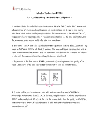
- 1. School of Engineering, FETBE EM203/208 (January 2013 Semester) - Assignment 2 1. piston–cylinder device initially contains steam at 200 kPa, 200°C, and 0.5 m3. At this state, a linear spring (F x) is touching the piston but exerts no force on it. Heat is now slowly transferred to the steam, causing the pressure and the volume to rise to 500 kPa and 0.65 m3, respectively. Show the process on a P-v diagram and determine (a) the final temperature, (b) the work done by the steam, and (c) the total heat transferred. 2. Two tanks (Tank A and Tank B) are separated by a partition. Initially Tank A contains 2-kg steam at 2MPa and 300°C while Tank B contains 3-kg saturated liquid–vapor mixture with a vapor mass fraction of 60 percent. Now the partition is removed and the two sides are allowed to mix until the mechanical and thermal equilibrium are established. If the pressure at the final state is 400 kPa, determine (a) the temperature and quality of the steam (if mixture) at the final state and (b) the amount of heat lost from the tanks. 3. A steam turbine operates at steady state with a steam mass flow rate of 4600 kg/h, producing a power output of 1000 kW. At the inlet, the pressure is 4 MPa, the temperature is 500C, and the velocity is 10 m/s. At the exit, the pressureis 0.1 bar, the quality is 0.9 (90%), and the velocity is 50 m/s. Calculate the rate of heat transfer between the turbine and surroundings,in kW.
- 2. 4. Refrigerant-134a is compressed in a compressor from an inlet state of 100 kPa, 10C to an outlet state of 1200 kPa, 60C. The compressor is water cooled with a heat loss amounting to 40 kW. The shaft work input is 150 kW. What is the mass flow rate (in kg/s) of the refrigerant through the compressor? 1200 kPa 60C 100 kPa 10C 5. A small turbine is operated at part load by throttling a 0.25 kg/s steam supply at 1.4 MPa, 250°C down to 1.1 MPa before it enters the turbine and the exhaust is at 10 kPa. If the turbine produces 110 kW, find the exhaust temperature and quality. 1.4 MPa 1.1 MPa 250C 110 kW 10 kPa
- 3. Solution 1. (a) We take the contents of the cylinder as the system. This is a closed system since no mass entersor leaves. Noting that the spring is not part of the system (it is external), the energy balance for thisstationary closed system can be expressed as The properties of steam are (Tables A-4 through A-6) Extract from 0.5 MPa section of Table A-6. (b) The pressure of the gas changes linearly with volume, and thus the process curve on a P-V diagram willbe a straight line.
- 4. P2 P1 V1 V2 The boundary work during this process is simply the area under the process curve, whichis a trapezoidal. Thus, (c) From the energy balance we have 2. We take the contents of both tanks as the system.This is a closed system since no mass enters or leaves. Notingthat the volume of the system is constant and thus there is noboundary work, the energy balance for this stationary closedsystem can be expressed as The properties of steam in both tanks at the initial state are The total volume f the system is The specific volume at the final stateis We can then determine the other properties at the final state as:
- 5. is obtained based on data below (taken from Table A-5): (b) Substituting, or, 3. 4600 kg/h 4 MPa 500C 10 m/s 0.1bar (10 kPa) 90% quality 50 m/s There is only one inlet and one exit, and thus . We take the turbine as the system, which is a control volume since mass crosses the boundary. The energy balance for this steady-flow system can be expressed in the rate form as steady Thus
- 6. Substituting =1101 kW 4. 100 kPa 10C There is only one inlet and one exit, and thus . We take the compressor as the system, which is a control volume since mass crosses the boundary. The energy balance for this steady-flow system can be expressed in the rate form as steady Thus
- 7. Substituting 5. 1.4 MPa 1.1 MPa 250C 110 kW 10 kPa There is only one inlet and one exit, and thus . We take the turbine as the system, which is a control volume since mass crosses the boundary. The energy balance for this steady-flow system can be expressed in the rate form as steady (assuming turbine is adiabatic) For the throttling process, h1 = h2. Hence Substituting
- 8. Inspection of the data from Table A-5 shows that hf<h3<hg. Hence state 3 is a saturated mixture phase and thus T3 = Tsat @ 10 kPa = 45.81C. The quality is Therefore