Offshore Drilling rigs (6) i
•Download as PPTX, PDF•
26 likes•5,083 views

Offshore drilling rigs: specificity, capacity ranges, generations and salient features

Recommended
More Related Content
What's hot
What's hot (20)
Similar to Offshore Drilling rigs (6) i
Similar to Offshore Drilling rigs (6) i (20)
Recently uploaded
Recently uploaded (20)
Offshore Drilling rigs (6) i
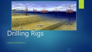
- 1. Drilling Rigs OKORO SOLOMON .U.
- 2. OUTLINE Systems of a drilling rig Broad classification of drilling rigs • Parts/ Features • Specificity • Capacity ranges • Pros and Cons • Evolution : 1st to Current Generation Types of drilling rigs (6 offshore rigs)
- 3. Systems of a drilling rig Hoisting system Rotating system Circulating system Well control system Power system Well monitoring system Mooring system (offshore)
- 4. Broad classification of drilling Rigs Classification of drilling rigs By Power used: Mechanical, Electric, Hydraulic, Pneumatic and Steam By location, Pipe used (cable, conventional and coiled tubing By Height: Single, double and triple By method of Rotation: non-rotation, rotary table, top drive, sonic, hammer.
- 5. Types of Drilling Rigs Drilling Rigs Land Rigs Conventional Mobile Offshore Rigs Floating Semi-submersible Drill Ship Bottom Supported Platform Barge Jack-up etc.
- 6. Semi-submersible Parts / Features • Subsea wellhead • Submerged pontoon keeps it afloat • Bottled or column stabilized • Connected to deck by columns • Moonpool below the derrick • Less cross-sectional area in the water line • High degree of stability • Dynamic positioning / anchor mooring Source: Offshore drilling volume 1
- 7. Semi-submersible specificity Transportation: Towed / self propelled Spudding the Rig: Temporary and permanent guide base adopted Stability: Tolerates harsh conditions as a result of space between the columns. compensate vertical motion using telescopic joint; tensioner system ; Wave motion compensator system Anchoring: use of conventional mooring / dynamic positioning with thrusters {short baseline system (4 hydrophones and at least one transponder) or Long baseline system (4 transducers and 4 transponders)} Functionality: Utilized in drilling exploratory and development wells.
- 8. Semi-submersible Capacity Ranges Specification Range Size (ft.) L*W*H 246 *230* 90 to 390* 260* 150 Water Depth (ft.) up to 12,000 Drilling depth (ft.) 25,000 to 40,000 Variable deck load (LT) 1,700 to 10,000 LT Hook load (ST) 200 t0 1500 Displacement 15,000 to 60,000 LT BOP rating psi 10,000 to 15,000 Derrick load 1,000,000 to > 2,000,000 lbs Mud pumps 2 to 6 pumps Quarters capacity 68 to 180 persons
- 9. Semi-submersible Pros • Mobile with high transit speed (~10 kts) • Highly stable with minimal response to wave action • Large deck area Pros and Cons Cons • High initial and operating costs • Limited deck load (due to buoyancy) • Structural fatigue • Expensive to move over large distances • Limited dry-docking facilities available • Difficulty in handling mooring systems and landing BOP stack in rough seas
- 10. Semi-submersible • Constructed 1961 - 1972 • Max depth - 1,500 ft. • Max variable deck load – 2k tons • BOP stack – 10,000 psi rating • Conventional mooring • No top drive 1st Gen • Constructed 1973 - 1979 • Max water depth – 2,000 ft. • Conventional mooring • No top drive 2nd Gen • Constructed 1980 - 1985 • Avg. WD – 2,500 ft. Max – 4000 ft. • Conventional and DP • No top drive • Built for harsh environments e.g. North Sea 3rd Gen • Constructed 1986 -1997 • Water depth- 2,500 to 6,500 ft. • DP and conventional • Top drive available • e.g. Oceanics Smith 3 4th Gen Evolution (First Semi-submersible: Shell’s Blue Water 1- 1962)
- 11. Semi-submersible • Constructed 1998 - 2004 • Water depth – 7,000 to 10,000 ft. • Most are DP (Dynamically positioned) • e.g. Sedco Forex Express 2000 5th Gen • Constructed 2009 onwards • Max water depth – 10,000 ft. • Dual derrick • Drilling depth > 30,000 ft • e.g. Ensco 8500s 6th Gen • 2015 onwards • Max water depth – 12,000 ft. • Dual derrick • Larger Variable deck load > 10,000 T • Drilling depth up to 40,000 ft. • Can accommodate dual BOPs 7th Gen Evolution
- 12. Drill Ship Parts / Features • Subsea wellhead • Self propelled • High storage capacity • Capacity for dual derrick • Dynamic positioning / anchor mooring Source: Offshore drilling volume 1
- 13. Drill Ship specificity Transportation: Self propelled Spudding the Rig: Temporary and permanent guide base adopted Stability: compensate vertical motion using telescopic joint; tensioner system ; Wave motion compensator system Anchoring: use of conventional mooring / dynamic positioning with thrusters {short baseline system (4 hydrophones and at least one transponder) or Long baseline system (4 transducers and 4 transponders)} Functionality: Utilized in drilling exploratory and development wells.
- 14. Drill Ship Capacity Ranges Specification Range Size (ft.) L*W 500 *120 to 800* 180 Water Depth (ft.) up to 14,000 Drilling depth (ft.) 20,000 to 45,000 Variable deck load (T) 3,000 to 30,000 T Hook load (ST) 200 to 1500 Power (kw) up to 100,000 BOP rating psi 10,000 to 20,000 Mud pumps 2 to 6 pumps Quarters capacity 68 to 250 persons
- 15. Drill Ship Pros • Mobile with high transit speed up to 16 kts • Greater deck and total load capacity than semi-submersible and jack-ups • Low mobilization costs • Low initial and operating costs • Superior sea worthiness and survival capability Pros and Cons Cons • Poor stability in rough sea areas • Minimum deck area • Difficulty in handling mooring systems and landing BOP stack in rough seas
- 16. Drill Ship • Constructed 1961 – 1970 • Drilling depth – 20,000 ft. • Max water depth – 1,000 ft. • Conventional mooring1st Gen • Constructed 1971 – 1979 • Max water depth – 1,500 ft. • Max drilling depth – 20,000 ft. • Conventional mooring 2nd Gen • Constructed 1980 – 1985 • Max water depth – 3,000 ft. • Max drilling depth - ~20,000 ft. • Conventional mooring 3rd Gen • Constructed 1986 -1997 • Max water depth – 7,000 ft. • Max drilling depth – 25,000 ft. • Dynamic positioning • VDL up to 8,000 T 4th Gen Evolution (Global Marine Drilling Company commissioned the first drill ship, CUSS I in 1956)
- 17. Drill Ship • Constructed 1998 – 2005 • Max water depth – 10,000 ft. • Dynamic Positioning • Drilling depth up to 30,000 ft. • Dual derrick • e.g. Saipem 10000 5th Gen • Constructed 2006 onwards • Max water depth – 10,000 ft. • Dynamic positioning • Dual activity • e.g. Ocean Rig Olympia 6th Gen • Constructed 2010 onwards • Max water depth – 12,000 ft. • Dynamic positioning • Dual activity rig • e.g. Ocean rig Athena 7th Gen Evolution
- 18. Jack-up Rig Parts / Features • Self Elevating • Surface wellhead • Movable legs • Derrick package as cantilever/ non cantilever • Jack-up legs: columnar or truss type • Hull (for ballasting and de-ballasting) Truss type Jack-up rig Source: Offshore drilling volume 1 Columnar Jack-up rig Source: Petrowiki.org
- 19. Jack-up Rigs specificity Jack-up Rigs Legs Columnar type Open Truss type Stabilization Mat supported Spud can Elevating devices Hydraulics Rack and pinion gears
- 20. Jack-up Rigs specificity Transportation: Self propelled / Towed Spudding the Rig: adequate soil testing; preloading (ballasting) the hull Stability: 3 legs are common, Truss legs aid stability. Air gap requirement. Anchoring: through the Legs of the jack-up; secondary anchors may be deployed Functionality: Utilized in drilling exploratory and also development wells (cantilever).
- 21. Jack-up Rig Capacity Ranges Specification Range Size (ft.) L*W*H 157* 132* 18 to 291* 336*39 Water Depth (ft.) Up to 625 Drilling depth (ft.) Up to 25,000 Cantilever load (lbm) 1m to 3mlb. Cantilever length (ft.) 25 to 90 Hook load capacity (kips) 1,400 to 2000 BOP rating psi 10,000 to 15,000 Variable Deck load (T) 1500 to 10,000 Mud pumps pressure (psi) Up to 7,500 Quarters capacity 50 to 120 persons
- 22. Jack-up Rig Pros • Mobility • Stable when elevated • Low cost (construction and maintenance) • Efficient Pros and Cons Cons • Dependent on weather windows for placement • Restricted to shallow areas • Sea flour erosion • Possible collapse as a result of soil fluidization from blowouts.
- 23. Jack-up Rig • Max depth - 300 ft. • Drilling variable deck load – 2k tons • Leg length – 300 to 400 ft. • No Cantilever 1970-1988 • Max water depth – 250 ft. • Drilling VDL – 1,900 tons • Leg length – 162 to 336 ft. • Cantilever load rating – 1m lbs. 1978 - 1982 • Max water depth – 300 ft. • Drilling VDL – 2,200 tons • Leg length – 251 to 417 ft. • Cantilever load rating – 1m lbs. 1981 - 1983 Evolution (Colonel Leon B Delong: first jack-up drilling rig, 1954 (Delong Corporation))
- 24. Jack-up Rig • Max water depth – 400 ft. • Drilling VDL – 4000 tons • Leg length – 496 to 540 ft. • Cantilever load rating – 1m to 2.5m lbs 1986 - date • Max water depth – 625 ft. • Drilling VDL – 10,000 tons • Leg length – up to 673 ft. • Cantilever load rating – 3m lbs. 2003 - date Evolution
- 25. Tension Leg Platform Parts / Features Source: www.phb/wordpress.com/2009/TLP • Drilling / Production • Vertical anchoring by tendons to piled seafloor templates • Tendons maintained in tension by buoyancy • Drilling through a drilling template • Hull: combination of Pontoons and columns • Use of pontoons in maintaining stability • Drilled with subsea wellhead. Tie-back to surface tree for production.
- 26. Tension Leg Platform specificity Transportation: Topsides lift / modular installed (foundation is built onshore and towed to site) Spudding the Rig: Foundation set using concrete piles (hammered), structure follows Stability: Provided by the tendons in tension. Ballasting to control tension. Use of hydraulic tensioners. Anchoring: Anchored using the tendons. Functionality: Utilized mainly for development wells
- 27. Tension Leg Platform Capacity Ranges Specification Range Height (ft.) 100 to 180 Water Depth (ft.) up to 5,000 Drilling depth (ft.) 20,000 to 25,000 Concrete piles (ft.) L*W Up to 500*100 Displacement (T) 10,000 to 100,000 Number of columns 1 to 4 BOP rating psi 10,000 to 15,000 Design Conventional / extended TLP Quarters capacity 68 to 150+ persons
- 28. Tension Leg Platform Pros • Mobile and reusable • Good stability with minimal vertical motion • Low incremental cost with increasing depth • Low maintenance cost • Possible in deep water Pros and Cons Cons • Initial cost is high • High subsea cost • Tension leg fatigue with time • Difficulty in maintaining subsea systems • Little storage capacity
- 29. Tension Leg Platform Evolution (First TLP built for Conoco Phillips’s Hutton Field 1984) 1984 (482 ft.) 2006 (5,000 ft.)
- 30. Spar Platform Parts / Features Spar platform. Source: www.worldoceanreview.com • SPAR: Single Point Anchor Reservoir • Drilling / Production • Catenary or taut mooring system • 3 designs available: Classic, truss and cell spar • Drilling through the center of the cylinder. • Drilled with subsea/surface wellhead. • Buoyancy cans adopted for stability
- 31. Spar specificity Transportation: Towed; Topside installed on site Spudding the Rig: Rig is towed to location and ballasted upright. Stability: Deep draft hull(90% submerged)/ buoyancy cans. Use of spiral fins / truss frame reduced vortex induced vibrations (VIV). Anchoring: Anchored using catenary or taut mooring system. Functionality: Utilized mainly for development wells
- 32. Spar Capacity Ranges Specification Range Height* width (ft.) 300 * 75 to 750 * 150 Water Depth (ft.) up to 8,000 Drilling depth (ft.) 20,000 to 30,000 Topside (T) Up to 4000 Draft (ft.) Up to 90% of height Number of well slots 15 to 30 BOP rating psi 10,000 to 15,000 Design 3 variations Quarters capacity 70 to 150+ persons
- 33. Spar Pros • Good degree of stability • Use of surface wellhead possible with reduced heave. • Lower costs with truss spar • Mobile Pros and Cons Cons • Susceptible vortex induced vibration. (classic spar) • Cost intensive with increasing water depth • Requires large facilities for manufacturing
- 34. Spar Platform Evolution (Genesis Spar 1998: First Spar with drilling facilities) • Classic Spar • Max water depth - 3,000 ft. • length – 700 to 750 ft. • Diameter – 70 to 120 ft. • e.g. Genesis Spar 1st Gen • Truss Spar • Max water depth – 6,000 ft. • Length – 500 to 650 ft. • Diameter – 90 to 110 ft. • e.g. Holstein Spar 2nd Gen • Cell Spar • Max water depth – 6,000 ft. • Length – up to 600 ft. • Diameter up to 100 ft. • e.g. Red Hawk Spar 3rd Gen
- 35. Spar Platform Evolution Classic Spar (WD 2000 – 5000 ft.) Cell Spar (WD 6,000 ft.) Truss Spar (WD 3500 – 6000 ft.)
- 36. Concrete Platform Parts / Features Concrete platform. Source: www.bolohair.uk • Gravity based, seat on seabed • Drilling / Production • No mooring required • Drilling through the center of the structure. • High storage capacity. • Variation: monopod and multi-pod.
- 37. Concrete Platform specificity Transportation: bottom section constructed in dry dock; towed to site and lowered to seabed; Topside installed on site. Spudding the Rig: Platform is towed to location and ballasted to seabed. Stability: stabilized by the weight of the structure (up to 850,000 T) resting on seabed. Anchoring: No anchoring system required. Functionality: Utilized for development wells (drilling and production).
- 38. Concrete Platform Capacity Ranges Specification Range Water Depth (ft.) up to 1200 Drilling depth (ft.) 20,000 to 30,000 Topside weight (T) 10,000 to 50,000 Substructure weight (T) 100,000 to 850,000 Number of well slots 30 to 50 Storage capacity mbbl 1m to 2m Design 2 variations Quarters capacity 100 to 180+ persons
- 39. Concrete Platform Pros • Cheap and easy installation • Low maintenance required • High storage capacity • Can withstand severe • No reduction in load carrying capacity with time. Pros and Cons Cons • Expensive capital cost • Challenges with decommissioning
- 40. Concrete Platform Evolution (First installed 1975: Beryl . A. Condeep) Source: www.industrytap.com
- 41. References Bradley H.B. (1992) “Petroleum engineering handbook”, Richardson, Society of Petroleum Engineers. Nguyen J.P. (2000) Drilling, Paris, Technip. Paolo Macini (2002) Offshore drilling, Volume 1. www. Petrowiki .org/history-of-offshore-drilling-units www. Essie.ufl.edu / ~sheppard/OCE3016/Offshore%20Structures.pdf www. Ocean-rig.com/ fleet www. Saipem.com www. Rigzone.com/training