1. TRANSPORTATION RESEARCH RECORD 1401 117
Hydroplaning and Roadway
Tort Liability
JOHN M. MüUNCE AND RICHARD T. BARTOSKEWITZ
Tort ciaims against highway agencies for alleged incidents of hy-
droplaning dueto roadway defects have been growing in number.
Many ciaims of hydroplaning cannot be substantiated by the
weather, roadway, or vehicie conditions present at the time of
the accident. And often when hydroplaning occurs, the evidence
indicates that an inappropriate response to adverse driving con-
ditions, or simply driver negligence, may be the direct cause rather
than a roadway defect. Research of the phenomenon of hydro-
planing was reviewed to address issues that arise when hydro-
planing is alleged in roadway tort litigation. Hydroplaning is the
separation of a rolling or sliding tire from the roadway surface
by a !ayer of fluid. Of the three types of hydroplaning commonly
recognized, highway engineers are primarily concerned with vis-
cous and dynamic hydroplaning. Of these two, dynamic hydro-
planing presents the greater risk. In the extreme situation of full
dynamic hydroplaning, complete separation of the tire from the
pavement by a fluid !ayer negates the driver's ability to control
vehicie speed and direction. Hydroplaning may be avoided by
consideration of severa! factors. Proper highway design may re-
duce hydroplaning risks by providing adequate pavement texture
and cross slope. However, ultimate responsibility for avoiding
hydroplaning lies with the driver. Drivers can reduce incidents
of hydroplaning by maintaining tires in good condition at rated
inflation pressures and by slowing down during rainstorms or on
wet roadways.
Rainfall and water present on the pavement surface influ-
ence the safety of motor vehicle operation. The latest national
accident statistics, compiled through 1990, indicate that ap-
proximately 10 percent of ali fatal crashes occur on wet pave-
ments during rainfall (1). In Texas, approximately 28 percent
of ali accidents are categorized as occurring during rainfall or
on wet pavements (2).
Motorists must be relied upon to recognize the degradation
of their ability to operate safely brought on by diminished
visibility through rainfall and reduced frictíon capabilities on
wet pavement. Many accidents in wet weather are dueto loss
of vehicle control, which results from either failure to rec-
ognize or to properly respond to adverse weather and pave-
ment conditions.
In recent years, an increasing number of tort lawsuits have
been filed against street and highway operating agencies with
allegations of roadway defects responsible for "hydroplan-
ing." In the adjudication of these lawsuits, many statements
have been made as to when, where, and how hydroplaning
occurs.. Most wet weather accidents are not caused by hydro-
planing. In reality, hydroplaning is a rare event, and its oc-
currence is dependent on many factors. This paper is a com-
Texas Transportation Institute, The Texas A&M University System,
College Station, Tex. 77843-3135. ·
pilation of research directed to the phenomenon of hydroplaning
as related to roadway tort litigation.
PHYSICS OF HYDROPLANING
A basic understanding of the function of pavement texture in
the tire-pavement interface is critica) to a discussion of the
mechanics of hydroplaning. Roadway surfaces are character-
ized by pavement microtexture and macrotexture. Microtex-
ture describes the degree of polishing of the pavement surface
or aggregate, varying from harsh to polished (3, Chapter 2),
and is necessary to the development of frictional forces be-
tween the tire and pavement on wet surfaces. The magnitude
of these frictional forces becomes greater with increased mi-
crotexture, and it is maximized at lower vehicle speeds (4).
When a thin !ayer of water is present, asperities on the pave-
ment surface break through the waterfilm to enable direct
contact between the tire and pavement (5). These asperities
are thousands of small, pointed projections that make up
microtexture. High local bearing pressures are generated by
contact between the tire tread and the pavement asperities,
thereby allowing the tire to establish essentially "dry" contact
with the roadway (6).
Macrotexture describes the size and extent of large-scale
protrusions from the surface of the pavement, varying from
smooth to rough. Macrotexture is a function of aggregate
gradation, the pavement construction method, and special
surface treatments such as grooving or chipping (3, Chapter
2). Whereas microtexture governs wet friction at low vehicle
speeds, macrotexture is the critica) factor for higher vehicle
speeds. Priction levels are significantly lower for pavements
with poor macrotexture than for pavements with good ma-
crotexture when vehicle speeds are high and flooded condi-
tions prevail. This is explained by the fact that macrotexture
provides channels for drainage, thereby reducing hydrody-
namic pressures existing between the tire and pavement when
water is present (4). Por a thin waterfilm and high vehicle
speeds, macrotexture is vital to establishing and maintaining
contact between the tire and pavement. Por a flooded pave- '
ment, it operates as escape channels for bulk water drainage
from beneath the tire footpi-int (6).
The physical phenomenon of hydroplaning is the separation
of a rolling or sliding tire from the roadway surface by a !ayer
of fluid. On a wet or flooded pavement, hydrodynamic pres-
sures increase as vehicle speed increases and eventually reach
a critica! point at which the tire is lifted away from the surface
(7}. Three types of hydroplaning have been identified: (a)
viscous hydroplaning, (b) dynamic hydroplaning, and (e) tread
2. 118
rubber reversion hydroplaning. Viscous and dynamic hydro-
planing are of concern when examining highway operations
on wet pavements.
Viscous hydroplaning is a problem associated with low-
speed operation on pavements with little orno microtexture.
lt results from an extremely thin film of water existing co-
hesively between the tire and the pavement surface because
of insufficient microtexture to penetrate and diffuse the fluid
!ayer. For this reason, viscous hydroplaning is commonly re-
ferred to as thin film hydroplaning to distinguish it from dy-
namic hydroplaning, which requires a comparatively thick
fluid !ayer.
Opinioñs on the importance of vehicle speed to viscous
hydroplaning vary. Yeager states that viscous hydroplaning
is observed at vehicle speeds greater than 32 km/hr (20 mph)
(8). However, Browne contends that viscous hydroplaning
can occur at any vehicle speed and with any waterfilm thick-
ness (9). The important point is that it may occur when vehicle
speeds are very low, such as with speeds typical of city driving.
The most critica! factors of influence during viscous hydro-
planing are the viscosity of the fluid, tire condition, and the
quality of the pavement surface. lt will not occur unless the
tire tread depth is very shallow and the pavement has a "pol-
ished" quality. Viscous hydroplaning may be described as a
rare event characterized by a bald tire operating on a mirror-
smooth surface.
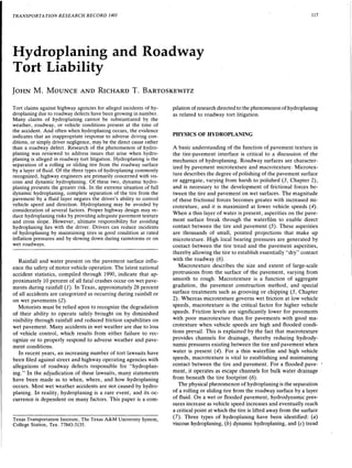
Dynamic hydroplaning results from uplift forces created by
a water wedge driven between a moving tire and the pavement
surface, as shown in Figure 1. The risk of dynamic hydro-
planing is high when fluid inertial effects dominate, as with
thick waterfilms found on a flooded pavement. Dynamic hy-
droplaning can only occur when the water accumulation en-
countered by the tire exceeds the combined drainage capacity
of the tire tread and the pavement macrotexture for a given
speed (9). For extreme conditions, it has been observed for
water depths as little as 0.76 mm (0.03 in.) with bald tires on
smooth, polished pavement surfaces (8).
A hydroplaning tire may experience either partía! or full
dynamic hydroplaning. With partía! dynamic hydropláning,
only part of the tire actually rides on the surface of the water.
Contact between at least a portion of the tire footprint and
the pavement surface is maintained. Full dynamic hydroplan-
ing, on the other hand, is characterized by complete sepa-
Vehicle Weighl
Uplifl Forces
FIGURE 1 Dynamic hydroplaning.
TRANSPORTA TJON RESEARCH RECORD 1401
ration of the tire from the pavement by the fluid )ayer. The
occurrence of full dynamic hydroplaning represents a far greater
hazard than partía! dynamic hydroplaning; the driver is unable
to control vehicle steering and braking because of the loss of
contact.
Speed and waterfilm thickness are the governing conditions
for partía! and full dynamic hydroplaning. It is difficult to
identify with precision the speed at which these phenomena
occur, because other variables that describe the roadway sur-
face, the tire condition, and the driving environment must be
considered. Whereas ordinary highway operating speeds and
water depths may give rise to partial dynamic hydroplaning,
considerably higher vehicle speeds anda very thick waterfilm,
such as that produced by high-intensity rainfall, are necessary
for full dynamic hydroplaning to occur (10). For most situa-
tions, the vehicle speed at which full dynamic hydroplaning
is observed would be considered unsafe or not prudent for
the amount of water on the roadway, assuming that the tire
tread is sufficient and that the tires are properly inflated.
FACTORS INFLUENCING ROADWAY
HYDROPLANING
Dynamic hydroplaning is a function of the complex interaction
between many variables. For this reason, the probability of
full dynamic hydroplaning is rather low (10). Factors critica!
to hydroplaning are shown in Figure 2. As can be seen, the
four primary effective variables are rainfall, the roadway, tire
characteristics, and the driver.
In general, hydroplaning is a low-probability event because
rainfall intensities necessary to flood a pavement surface are
rare and of short duration (11). Furthermore, rainfall intensi-
ties of sufficient magnitude [5.1 to 10.2 cm/hr (2 to 4 in./hr)]
to create sheet flooding of pavement surfaces reduce visibility
even with wipers so that prudent drivers will reduce operating
speeds for safety (10).
Drainage path length refers to the distance any discrete
water molecule would have to negotiate to drain from a given
point on the pavement surface. It is a function of the number
of lanes of travel and the Jane width. A typical two-lane,
TIRE
* Pressure
* Footprint
Ratio
ROAD
* Texture
* Cross
Slope
DRIVER
* Recognition
* Actions
Probability of Hydroplaning
RAINFALL
* Inlensity
* Drainage
Palh
FIGURE 2 Synthesis of interactive factors
influencing hydroplaning.
3. Mounce and Bartoskewitz
crowned cross section has a nominal drainage path length of
3.66 ft. This factor is especially significant for water accu-
mulations that result from extended drainage path lengths
associated with multilane roadways. An investigation of po-
tential meaos of decreasing the occurrence of hydroplaning
concluded that minimizing the drainage path length through
careful highway design and construction is an effective strat-
egy (11). When multiple travel lanes are present, the negative
impact of longer drainage path lengths can be mitigated through
appropriate application of pavement cross slope and pave-
ment texture.
Roadway factors of pavement texture and transverse cross
slope are critica! to controlling water accumulation and drain-
age. A transverse cross slope of 2.5 percent is desirable to
facilitate adequate surface drainage for common rainfall in-
tensities without impeding vehicle steering or lane-changing
maneuvers (10).
The role of pavement texture in collecting and draining sur-
face water from the vehicle path has already been addressed.
Balmer and Gallaway (1J) reported the results of an extensive
investigation of applications of pavement texture to reduce
the risk of hydroplaning and to improve wet traction. The use
of a gritty, coarse surface texture or finish in the construction
and maintenance of pavements was recommended.
Providing texture depth is also critica! because deeper tex-
tures act as larger escape channels for water forced from
beneath the tire footprint region. Balmer and Gallaway dis-
covered that increasing the texture depth from 0.76 mm (0.03
in.) to 3.81 mm (0.15 in.) raised the speed at which dynamic
hydroplaning was predicted to occur by 16.1 km/hr (10 mph)
for tire inflation pressure of 206.85 kPa (30 psi), tire tread
depth of 6.75 mm (8.5/32 in.), and water depth of 7.6 mm
(0.3 in.). lt was also concluded that transverse texture, aligned
parallel to the cross slope direction, can be expected to pro-
vide improved overall surface drainage, improved water ex-
pulsion between the tire and the pavement, and a decrease
in the forward motion ofwater responsible for creating a water
wedge between the tire and pavement.
Pavement texture depth of 1.52 mm (0.06 in.) or greater
is the recommeñded mínimum for roadwáys with high oper-
ating speeds. This will provide adequate drainage and de-
crease hydroplaning for normally expected rainfall rates (10).
For roadways with low-speed operation, even less texture
depth may be tolerable. However, even under the best design
and construction conditions, storms of unusually high inten-
sity, though rare, are likely to create flooding of the pavement
surface above the texture asperations.
The tire is one of the most critica! factors influencing
hydroplaning. Even on a well-designed, properly maintained
roadway, a worn, under-, or overinflated tire experiences
considerably higher risk of hydroplaning than does a tire
in "good" shape, for normally expected rainfall and pru-
dent speed. Yeager (8) and Browne (9) have addressed
factors of tire constructton and condition that influence
hydroplaning.
Tread pattern is one of these factors. Lateral and longi-
tudinal grooves, sipes, and ribs make up the tire tread pattern.
Grooves are the deep channels that run around the circum-
ference of the tire (longitudinal grooves) and across the tire
surface (lateral grooves). Tliey serve two principal functions.
By channeling bulk water through and out of the tire footprint
119
region, grooves help to prevent the formation of the water
wedge that penetrates into the footprint region and causes
dynamic hydroplaning. They also function as reservoirs for thin
waterfilms squeezed from between the tire and the pavement
surface, which reduces the risk of viscous hydroplaning (9).
Four parameters describe the effectiveness of the tread
grooves with respect to wet traction and hydroplaning: tread
depth, groove capacity, groove shape, and groove spacing.
Tread depth is primarily a measure of how much tread re-
mains on a tire after experiencing wear as a result of extended
use. When the tire is worn to an extent such that the depth
of tread reaches a mínimum safe value, tire replacement is
recommended.
The amount of surface water to be effectively handled is
referred to as the tire's groove capacity. It is related to tread
depth and influenced by tire construction, load, and inflation
pressure. Once the amount of pavement surface water en-
countered by the tire tread exceeds the groove capacity, the
excess water must have sufficient time to be displaced without
building up in front of the tire and creating uplift pressure on
the tire. Higher vehicle speeds reduce the time of displace-
ment and increase the risk of hydroplaning.
Another determining factor of groove capacity is groove
closure. The effect of groove closure is a considerable reduc-
tion in the tread's groove capacity. This phenomenon depends
on the structural properties of the tire tread, the rotational
speed of the tire, and the inertial forces of the fluid layer that
the tire encounters. It is a direct consequence of lateral forces
acting in the tire ribs toward the longitudinal centerline of
the tire footprint. Groove closure is resisted by frictional forces
between the tire and the pavement. However, in the absence
of these frictional forces, such as on a wet pavement, no force
exists to counteract groove closure. Groove closure has been
found to be less of a problem for radial tires than for bias
tires (8).
Groove shape and spacing influence a tire's wet traction
capabilities and performance. Groove shape is especially im-
portant for a sliding tire, as opposed to a free rolling tire (8).
Wide grooves provide optimum flow characteristics and mit-
igate the effects of groove closure. Slight amounts of zigzag
with qiagonal grooves are also desirable. For a free rolling
tire, groove capacity is the controlling factor, although di-
agonal grooves and blading help to reduce the risk of viscous
hydroplaning on a smooth surface. Grooves should be closely
spaced to achieve peak traction performance.
Other tire factors relating to hydroplaning imd wet traction
may be generally categorized as elements of the tire carcass.
These include tire dimensions and flexibility. The region of
contact between the tire and pavement, the tire footprint, is
measured by length and tire width. As tire width increases,
the width of the footprint increases. On a wet or flooded
pavement, this is important because the tire will encounter
and interact with a greater amount of fluid than it would have
otherwise. Accordingly, the task of collecting and channeling
water away from the tire footprint becomes more difficult and
requires a greater length of time, and the magnitude of hy-
drodynamic forces acting on the tire is greater. But whereas
increasing the width of the contact region is potentially det-
rimental, increasing its length results in greater amounts of
dry contact within this region. It follows that wet traction
performance and safety are enhanced.
4. 120
The effects of tire footprint dimensions on dynamic hydro-
planing speed have recently been investigated (12-14). The
tire footprint aspect ratio is calculated as the tread contact
area width divided by the length of the footprint (Figure 3).
It is of particular interest in analyzing the hydroplaning ten-
dency of tractor-trailer trucks. Aspect ratios for trucks are
influenced by the magnitude of the load. The footprint aspect
ratio for an empty truck is considerably higher than for a
loaded truck, when holding inflation pressure constant, due
to shorter tire footprints for empty trucks. As explained pre-
viously, this results in less dry contact area between the tire
and the pavement. Furthermore, accident statistics show that
jackknifing of empty tractor-trailer trucks on wet pavements
is a significant event that may be attributed to dynamic hy-
droplaning. lt was determined that the footprint aspect ratio
is a variable that must be considered when estimating dynamic
hydroplaning speeds for pneumatic tires.
Tire construction and inflation pressure govern tire flexi-
bility. Bias ply, belted bias ply, and radial ply are the three
common methods of tire construction. With respect to de-
creasing the potential of the tire to hydroplane, belted bias
ply and radial tires are preferred. The treads of these tires
have improved stability, provided by belts under the tread
region. This serves to reduce tire tread wear and groove clo-
sure and makes possible the inclusion of exaggerated tread
pattems that reduce hydroplaning risks (9).
The function of tire inflation pressure in raising or lowering
a tire's hydroplaning tendency is difficult to analyze and eval-
uate. lt has been shown that for dynamic hydroplaning to take
place, the tire surface must deform inward, toward the center
of the tire. When this deformation is present, water can pen-
etrate deeper into the tire footprint to create the water wedge
that can eventually lead to full dynamic hydroplaning. Higher
inflation pressure improves the tire's rigidity and its ability to
resist the hydrodynamic forces causing tire surface defor-
mation, thereby raising the speed required for hydroplaning
L
TRANSPORTATJON RESEARCH RECORD 1401
to occur. lt also counteracts the lateral forces in the tire ribs
that encourage groove closure. The drawback, however, is
shortening of the tire footprint and the ensuing reduction of
the dry contact area between the tire and pavement. This
essentially lowers the hydroplaning speed (9).
Roadway, vehicle, and environmental factors that interact
to create hydroplaning have been mentioned. The driver's
recognition of and response to these various factors are crit-
ica!. Drivers avert hydroplaning by direct action, for instance
by maintaining safe speeds on wet roadways. They can also
indirectly reduce the potential for hydroplaning through a
careful program of tire maintenance.
PREDICTING AND IDENTIFYING
HYDROPLANING SPEEDS
Substantial effort has been devoted to the development of
formulas and criteria to identify the precise speed at which
hydroplaning occurs. The most common approach has been
to calculate the critica! speed required for dynamic hydro-
planing. Sorne of these equations are simple relationships
defining the hydroplaning speed as a function of one or two
variables. Others are considerably more complex. As might
be expected, the task of predicting when hydroplaning will
occur, or of identifying a particular wet-weather accident as
a hydroplaning incident, is rather difficult and involves a sub-
stantial degree of uncertainty. The purpose of this section is
to briefly describe sorne of the analytical and empirical tech-
niques for evaluating hydroplaning potential.
In the case of viscous hydroplaning, Equation 1 describes
the minimum hydroplaning speed for a pavement surface with
slight microtexture:
L
V >--
H- l::,,.T
sf
Water
tttttt Tread Pattern
Tread Grooves
Direction of Travel
(1)
ASPECT RATIO
W + L
w
FIGURE 3 Tire footprint-pavement view.
5. Mounce and Bartoskewitz
where
VH = minimum viscous hydroplaning speed,
L = length of the tire footprint region, and
liT,1 = time required for sufficient reduction of the fluid
film for contact between the tread rubber and the
pavement asperities to occur (9).
This formula is not applicable to dynamic hydroplaning.
Yang has proposed an analytical equation to define hydro-
planing as par't of an effort to develop design criteria for
runway pavement grooving (15). The underlying principie for
this equation is that hydroplaning will occur when the water
escape velocity due to an externa! force, the tire pressure, is
less than the speed at which the surface water travels sideways.
The critica! moment at which hydroplaning occurs is defined
by Equation 2:
( 7J'llV)
cp112 = 0.1292 b
where
e = constant,
p = tire inflation pressure (kPa),
a = width of the tire footprint (cm),
b = length of tire footprint (cm), and
v = vehicle velocity (cm/sec).
For U.S. customary units, Equation 2 is rewritten as
i12 - 7J'a/4
cp - 2blv
where
e = constant,
p = tire inflation pressure (lbf/in.2),
a = width of the tire footprint region (in.),
b = length of the tire footprint region (in.), and
v = vehicle velocity (in./sec).
(2)
(3)
The development of this equation assumes an elliptical tire
footprint shape.
One of the most frequently cited hydroplaning equations
was developed by Home to predict the minimum dynamic
hydroplaning speed for pneumatic tires (16). In its simplified
form, this equation is
VH = 6.35Vp (4)
which yields the minimum tire hydroplaning speed VH (km!
hr) as a function of the tire inflation pressure p (kPa). In U.S.
customary units, Equation 4 is given by
(5)
where the mínimum tire hydroplaning speed VPis in mph and
the tire inflation pressure pis in lbf/in.2 The formula is derived
from empirical data and based on inertial properties of the
fluid !ayer. It is applicable to flooded pavements, when the
water depth exceeds the tire tread depth.
121
Recent research has indicated that the mínimum dynamic
hydroplaning speed of automobile, truck, and bus tires varies
not only with the inflation pressure but also with the tire
footprint aspect ratio (12-14). Consequently, Home pro-
posed a modification of bis earlier formula to account for the
influence of the footprint aspect ratio under load. Simplified,
this new equation may be written as Equation 6:
(6)
where wll is the tire footprint aspect ratio, the tire inflation
pressure pis in kPa, and the minimum tire hydroplaning speed
VH is in km/hr. For U.S. customary units, Equation 6 may
be written as
(7)
which yields the speed VP in mph as a function of the tire in-
flation pressure p in lbf/in.2 lt is seen that the magnitude of the
mínimum dynamic hydroplaning speed increases as the tire
inflation pressure increases and the tire footprint aspect ratio
decreases (12). Research at the Texas Transportation Institute
(TTI) investigated the validity of Horne's predictions of dy-
namic hydroplaning of lightly loaded truck tires at typical
highway speeds (13). TTI engineers formulated the relationship
( )
0.5
V= 24.99(p)021 ~~ (8)
normalized for the test aspect ratio of 1.4. In U.S. customary
units, Equation 8 is written as
V= 23.3(p)º 21 (~irs (9)
Although Equations 8 and 9 differ from Equations 6 and 7,
they yield curves that agree closely over the range of test
conditions.
A study by Gallaway et al. (17) developed an empirical
formula for dynamic hydroplaning speed when the waterfilm
thickness exceeds 0.10 in. Multiple linear regression yielded
the following expression:
V = 0.902SD004P03 TD +
( l)o.o6A
0.794
(10)
where A is the greater of
( 11.008 )
A = WDºº6 + 3.507 (11)
or
A = ( 26·871 - 6 861) TXDº 14
WD0 ·06 •
(12)
and V is the vehicle speed (km/hr), SD is the spindown per-
centage, Pis the tire inflation pressure (kPa), TD is the tread
depth (mm), WD is the water depth above the pavement
asperities (cm), and TXD is the pavement texture depth (cm).
6. 122
To indicate the point at which hydroplaning occurs, the spin-
down parameter was used. Spindown describes the change in
a free rolling tire's rotational velocity upon loss of contact
with the pavement surface, as in full dynamic hydroplaning.
When U.S. customary units are used, Equation 13 is applied:
V = SD004 P03 (TD + l)006A (13)
where A is the greater of
( 10.409 )
A = WDº·º6 + 3.507 (14)
or
A = [ 28·952 - 7 817]TXDº·14
WD0 ·06 •
(15)
and V is expressed in mph, Pis in lbf/in.2 , TD is given as
32nds of an inch, and WD and TXD are expressed in inches.
Two studies conducted at The Pennsylvania State Univer-
sity have investigated hydroplaning speeds. Agrawal et al.
(18) ranked highway pavement performance by evaluating the
hydroplaning potential of various pavement treatments. The
dynamic hydroplaning speed was determined indirectly by
measuring the brake force coefficient, the friction value that
describes the tire-pavement interface. lt was assumed that ful!
dynamic hydroplaning occurs when the brake force coefficient
is zero.
Huebner et al. (19) developed a hydroplaning model that
draws on the work of both Gallaway and Agrawal. For wa-
terfilm thicknesses greater than 0.25 mm (0.10 in.), Galla-
way's equation for the critica! dynamic hydroplaning speed
was adopted. A regression of 18 data points collected by the
Agrawal study for waterfilm thicknesses less than 0.25 cm
(0.10 in.) was performed. The relationship
HPS = 53.34 (WFT)- 02s9 (16)
was obtained for the dynamic hydroplaning speed HPS (km/
hr) as a fünction of the waterfilm thickness WFT (cm). In
U.S. customary units, the equátion is
HPS = 26.04 (WFT)-02s9 (17)
for the dynamic hydroplaning speed HPS in mph and the
waterfilm thickness WFTin inches. The study noted that con-
siderably more data are required to accurately establish this
relationship for waterfilm thicknesses less than 0.25 cm (0.10
in.). However, the critica! hydroplaning speed under this con-
dition is much higher, and full dynamic hydroplaning speed
is less likely to occur for waterfilms of this depth at legal
highway speeds.
LIABILITY FOR HYDROPLANING
Ali of the previously discussed factors- tire inflation pres-
sure, tread depth and design, pavement texture depth, pave-
ment slope, drainage path length, and rainfall intensity-
influence hydroplaning occurrence. But the recognition of
TRANSPORTATION RESEARCH RECORD 1401
environmental conditions creating sufficient water depths on
the pavement for the possibility of hydroplaning, and the
action of sustaining a reasonable operating speed under those
conditions, is the responsibility of the driver.
Loss of control due to high or unsafe speed is the direct
cause of most wet-weather accidents. If the driver chooses to
ignore high-intensity rainfall and continues to operate at speeds
considered high for the existing conditions, the probability of
dynamic hydroplaning is increased. With full dynamic hydro-
planing, the driver loses control over vehicle steering and
braking.
Driver expectations during rainfall must be realistic and
reasonable. Operating at posted speed limits greater than 80
km/hr (50 mph) under heavy rainfall places the driver at risk
of dynamic hydroplaning. Citations issued by law enforcement
personnel in many of these cases charge the driver with op-
erating the vehicle at a "speed unsafe for conditions" or "fail-
ure to control speed." Highway engineers must rely on the
prudence and reasonable operation of drivers during times of
rainfall or when water is on the pavement. Speed should be
reduced below 80 km/hr (50 mph) to decrease the probability
of full dynamic hydroplaning (10). Overt actions or reactions
by braking or steering should be carefully controlled when
encountering water on the pavement surface, because friction
capability is significantly reduced.
Responsibility for proper tire care and maintenance also
lies with the driver. Drivers must be relied upon to maintain
tire inflation pressures in accordance with the manufacturer's
specifications. Although the recommended inflation pressure
varíes for different types of tires, it is typically at or above
206.85 kPa (30 psi) for most passenger car tires. Tire care
and maintenance also imply the driver's responsibility to mon-
itor tire tread wear regularly and to reduce the effects of tread
wear on tire performance and safety by properly balancing
and rotating the tires at regular intervals. Tire tread depth
should be a mínimum of 0.159 cm (2/32 in.) to reduce the
vehicle's susceptibility to hydroplaning and to obtain optimum
wet traction performance (10).
Highway engineers have responsibility (liability) for prop-
erly designing, constructing, and maintaining the roadway
pavement to adequately drain surface water from normally
expected rainfalls. This includes the recognition and reme-
diation of pavement defects, failures, or areas prone to the
possibility of ponding water. However, as stated previously,
under the most desirable methods of design, construction,
and maintenance of a roadway for pavement surface drainage,
an atypical, high-intensity rainstorm can produce sheet flood-
ing or water ponding such that hydroplaning can occur.
Both transverse and longitudinal areas of water puddling
may develop on roadways because of wheel loads or failure
of the pavement over time. These "ruts" trap water and are
most likely to occur on flexible pavements and be of short
length. Studies indicate that hydroplaning can occur in these
areas when the length of the rut is 9.144 m (30 ft) or greater.
However, with normal cross slopes (::s2.5 percent), rut depths
of 0.61 cm (0.24 in.) or less do not significantly contribute to
a higher risk of hydroplaning (11).
Special attention must be given by highway engineers to
areas on roadways prone to ponding of water under high-
intensity rainfall rates. Drainage facilities should be empha-
sized that will rapidly collect and remove water from locations
7. Mounce and Bartoskewitz
of flat or sag vertical profile that are susceptible to hydro-
planing under heavy rainfall conditions.
Horizontal alignment tránsition areas with superelevation
also may create a "flat spot" in the transverse cross section
of a roadway. This is an especially critica! point where little
or no longitudinal slope exists to drain water away from the
traveled way. Highway engineers must anticipate the possi-
bility of ponding water on the pavement in this situation under
high-intensity rainfall and introduce drainage adjustments to
minimize the probability of hydroplaning.
HYDROPLANING AND ROADWAY TORT
LITIGATION
An increasing number of wet weather accidents have resulted
in lawsuits with claims of proximate cause being water on the
pavement surface inducing loss of control through hydro-
planing. Toe allegations in this litigation may be focused in
two areas: encountering sheet flooding or ponded areas of
water on the pavement surface and testimony regarding op-
erating speed and loss of control. The following hypothetical
legal cases involving hydroplaning and tort liability are pre-
sented to illustrate typical allegations versus factual evidence
and failure to fulfill duties (negligence) by either the driver
or the highway agency.
Case 1
Driver A was proceeding through a right-hand curve on a
two-lane, asphalt roadway during a moderate rain shower in
daylight. Just before completing the curve, Driver A lost con-
trol of the vehicle and crossed the centerline of the roadway,
sliding broadside into an opposing vehicle and injuring Driver
B. Driver A filed suit against the highway agency, alleging
that loss of control was due to hydroplaning, which resulted
from a roadway defect.
At the time of the accident, the roadway curve was well
marked and signed with an advance curve warning and an
advisory speed plate of 64 km/hr (40 mph). Radius of cur-
vature and cross slope (superelevation) were shown to be in
compliance for the classification of roadway and posted op-
erating speed. Tne pavement surface was well traveled, yet
shown to have a good coefficient of friction. No record of
complaints of comparable accidents at the same curve location
were found within a prior 3-year period. Both vehicles were
assessed in good mechanical condition, and their tires were
in adequate condition and properly inflated.
Driver A testified to a precollision speed below 64 km/hr
(40 mph). Damage to both vehicles indicated an impact speed
of greater than 80 km/hr (50 mph). The alleged hydroplaning
most probably would not have occurred at a speed of 64 km/
hr (40 mph) or less at this site under these geometric, pave-
ment, and tire conditions. Toe broadside skid was also indic- ·
ative of excessive speed above that posted and critica! for the
curve alignment.
Case 2
Driver C was traveling on a rural Interstate highway with a
posted regulatory speed of 104 km/hr (65 mph) approaching
123
a severe rainstorm. On encountering the rainfall, the vehicle
ran off the roadway and struck a tree within the divided me-
dian. Driver C sustained injuries in the collision, for which
suit was brought against the operating agency alleging hydro-
planing to be the cause of loss of vehicle control.
Toe highway was a four-lane, divided, tangent section at
the point ofvehicle departure from the roadway. The roadway
surface had been recently overlain with asphaltic concrete,
providing a high frictional ·coefficient. Cross slope at the lo-
cation was measured and found to be in compliance with
published criteria.
Driver C testified that he was traveling at 104 km/hr (65
mph) when loss of vehicle control occurred. Other motorists
testified to reducing speed to 80 km/hr (50 mph) because of
the obvious reduction in visibility and extent of water on the
pavement from the rainstorm. Meteorological data indicated
the rainfall intensity for the thunderstorm associated with the
accident to be near 10.2 cm/hr (4 in./hr) and the cause of
flooding damage.
In this case, Driver C may have lost control of the vehicle
as a result of hydroplaning upon encountering water on the
pavement surface of considerable depth. Driver C may have
left the roadway because of poor visibility or may have lost
control of the vehicle as a result of inappropriate steering or
braking reactions to hydrodynamic forces. However, it is likely
that this accident was the direct result of Driver C's failure
to recognize and respond to adverse weather conditions. Rea-
sonable and prudent action on the part of Driver C, in the
forro of a speed reduction, would have likely avoided this
accident.
Case 3
Driver D was traveling on a two-lane, asphalt roadway en-
tering a left-hand curve during slight rainfall. Loss of control
caused the vehicle to continue in a straight line off an em-
bankment to the outside of the curve. Driver D alleged that
water encountered on the roadway caused hydroplaning and
the subsequent loss of vehicle control. Suit was brought against
the operating agency for negligence in design, construction, ·
and maintenance resulting in a highway defect.
Driver D testified that he was traveling at the posted speed
limit of 88 km/hr (55 mph) at the time of the accident. The
pavement surface was wom and polished with a marginal, yet
adequate, coefficient of friction. The location of the water
encountered was determined to be in the superelevation tran-
sition from normal, crown cross slope to banked cross slope
(superelevation). The transverse grade of an area on the road-
way in this transition was measured and determined to be less
than 0.05 percent. This "flat" area was compounded by also
being at the sag (low) point of a longitudinal vertical grade.
Furthermore, evidence indicated an average of five compa-
rable accidents per year for this site for the 3 years before the
accident. ·
For the existing geometric and pavement conditions, it was
possible for hydroplaning to have occurred because of water
on the roadway for a motorist traveling at the posted speed
limit under normally expected rainfall intensitiés. The path
of departure also indicated little orno vehicle control, typical
of full dynamic hydroplaning. The agency had a duty and
8. 124
responsibility to recognize the combination of conditions con-
ducive to poor drainage of the roadway and to remediate those
conditions.
CONCLUSIONS
Many roadway tort liability claims are being made with little
or no factual basis to substantiate allegations of hydroplaning
as a causative factor. The physical phenomena of dynamic
hydroplaning can only be possible at a designated mínimum
speed when water depth on the roadway exceeds the com-
bined surface macrotexture depth and tire tread depth. Other
factors of influence, such as tire inflation pressure and tire
footprint size and shape, may adjust the calculation óf the
critica! hydroplaning speed.
Highway engineers have responsibility for roadway factors
affecting friction capability, such as pavement texture design
and depth, and surface drainage, such as cross slope, super-
elevation transition, longitudinal grade, and length of the
transverse drainage path. Engineers must design, construct,
and maintain streets and highways in a manner ensuring proper
surface drainage to minimize the probability of water accu-
mulation under normal rainfall conditions.
Motorists must also accept responsibility for their driving
behavior during periods of rainfall. A reasonable and prudent
driver should recognize the greater potential danger of op-
erating a vehicle in a wet roadway environment and reduce
vehicle speed to minimize the risk of losing control of the
vehicle. For most cases of full dynamic hydroplaning (assum-
ing adequate tire tread and proper tire inflation), the vehicle
speed at which hydroplaning is observed would be considered
unsafe or not prudent for the amount ofwater on the roadway.
Judges and juries in cases of roadway tort litigation must
determine whether hydroplaning occurred and its relevance
as a causative factor in many accidénts. In addition, assess-
ment must be made as to responsibility for conditions that
result in hydroplaning. These decisions can only be made with
factual information about the physical phenomenon of hy-
droplaning and factors influencing both the roadway and ve-
hicle. It is hoped that this paper has addressed issues relevant
to hydroplaning and roadway tort litigation in an informative
and helpful manner.
REFERENCES
l. Fatal Accident Reporting System. DOT-HS-807-794. NHTSA, U.S.
Department of Transportation, Dec. 1991.
2. Single Variable Accident Tabulations. Texas Department of
Transportation, July 1992.
3. Road Surface Characteristics: Their Interaction and Their Optim-
isation. Organisation for 1=,conomic Cooperation and Develop-
ment, París, 1984.
4. J. S. Creswell, D. F. Dunlap, and J. A. Green. NCHRP Repon
176: Studded Tires and Highway Safety~· Feasibility ofDetermining
TRANSPORTATION RESEARCH RECORD 1401
lndirect Benefits. TRB, National Research Council, Washington,
D.C., 1977.
5. R. Pelloli. Road Surface Characteristics and Hydroplaning. In
Transportation Research Record 624, TRB, National Research
Council, Washington, D.C., 1976.
6. W. B. Home. Status ofRunway Slipperiness Research. In Trans-
portation Research Record 62ll, TRB, Na.tional Research Council,
Washington, D.C., 1976.
7. W. B. Home and F. Buhlmann. A Method for Rating the Skid
Resistance and Micro/Macrotexture Characteristics ofWet Pave-
ments. In Frictional Interaction of Tire and Pavement, ASTM
STP 793 (W. E. Meyer and J. D. Walter, eds.), American Society
for Testing and Materials, 1983, pp. 191-218.
8. R. W. Yeager. Tire Hydroplaning: Testing, Analysis, and De-
sign. In The Physics of Tire Traction: Theory and Experiment
(D. F. Hays and A. L. Browne, eds.), Plenum Press, New York,
1974.
9. A. L. Browne. Mathematical Analysis for Pneumatic Tire Hy-
droplaning. In Surface Texture Versus Skidding: Measurements,
Frictional Aspects, and Safety Features of Tire-Pavement lnter-
actions, ASTM STP 583, American Society for Testing and Ma-
terials, 1975, pp. 75-94.
10. B. M. Gallaway, F. C. Benson, J. M. Mounce, H. H. Bissell,
and M. J. Rosenbaum. Pavement Surface. In Synthesis of Safety
Research Related to Traffic Control and Roadway Elements, Vol.
l. FHWA-TS-82-232. FHWA, U.S. Department of Transpor-
tation, Dec. 1982.
11. G. G. Balmer and B. M. Gallaway. Pavement Design and Con-
trols for Minimizing Automotive Hydroplaning and Increasing
Traction. In Frictional lnteraction of Tire and Pavement, ASTM
STP 793 (W. E. MeyerandJ. D. Walter, eds.), American Society
for Testing and Materials, 1983, pp. 167-190.
12. W. B. Home. Predicting the Mínimum Dynamic Hydroplaning
Speed for Aircraft, Bus, Truck, and Automobile Tires Rolling
on Flooded Pavements. Presented to ASTM Committee E-17
Meeting at the Texas Transportation Institute, College Station,
Tex., June 1984.
13. D. L. Ivey. Truck Tire Hydroplaning-Empirical Confirmation
of Horne's Thesis. Texas Transportation Institute, Texas A&M
University System, College Station, Nov. 1984.·· ·
14. W. B. Home, T. J. Yager, and D. L. Ivey. Recent Studies To
Investigate Effects of Tire Footprint Aspect Ratio on Dynamic
Hydroplaning Speed. The Tire Pavement Interface, ASTM STP
929 (M. G. Pottinger and T. J. Yager, eds.), American Society
for Testing and Materials, Philadelphia, Pa., 1986, pp. 26~46.
15. N. C. Yang. Design ofFunctional Pavements. McGraw-Hill Book
Company, New York, 1972.
16. W. B. Home and U. T. Joyner. Pneumatic Tire Hydroplaning
and Sorne Effects on Vehicle Performance. SAE Paper 970C,
Jan. 1965.
17. B. M. Gallaway, D. L. Ivey, G. Rayes, W. B. Ledbetter, R.M.
Olson, D. L. Woods, and R. F. Schiller, Jr. Pavement and Geo-
metric Design Criteria for Minimizing Hydroplaning. FHWA-
RD-79-31. FHWA, U.S. Department of Transportation, Dec.
1979.
18. S. K. Agrawal, W. E. Meyer and J. J. Henry. Measurement of
Hydroplaning Potential. FHWA-PA-72-6. Pennsylvania Trans-
portation Institute, Toe Pennsylvania State University, Feb. 1977.
19. R. S. Huebner, J. R. Reed, and J. J. Henry. Criteria for Pre-
dicting Hydroplaning Potential. Journal of Transportation En-
gineering, Vol. 112, No. 5, Sept. 1986, pp. 549-553.
Publication of this paper sponsored by Committee on Tort Liability
and Risk Management.
![118
rubber reversion hydroplaning. Viscous and dynamic hydro-
planing are of concern when examining highway operations
on wet pavements.
Viscous hydroplaning is a problem associated with low-
speed operation on pavements with little orno microtexture.
lt results from an extremely thin film of water existing co-
hesively between the tire and the pavement surface because
of insufficient microtexture to penetrate and diffuse the fluid
!ayer. For this reason, viscous hydroplaning is commonly re-
ferred to as thin film hydroplaning to distinguish it from dy-
namic hydroplaning, which requires a comparatively thick
fluid !ayer.
Opinioñs on the importance of vehicle speed to viscous
hydroplaning vary. Yeager states that viscous hydroplaning
is observed at vehicle speeds greater than 32 km/hr (20 mph)
(8). However, Browne contends that viscous hydroplaning
can occur at any vehicle speed and with any waterfilm thick-
ness (9). The important point is that it may occur when vehicle
speeds are very low, such as with speeds typical of city driving.
The most critica! factors of influence during viscous hydro-
planing are the viscosity of the fluid, tire condition, and the
quality of the pavement surface. lt will not occur unless the
tire tread depth is very shallow and the pavement has a "pol-
ished" quality. Viscous hydroplaning may be described as a
rare event characterized by a bald tire operating on a mirror-
smooth surface.
Dynamic hydroplaning results from uplift forces created by
a water wedge driven between a moving tire and the pavement
surface, as shown in Figure 1. The risk of dynamic hydro-
planing is high when fluid inertial effects dominate, as with
thick waterfilms found on a flooded pavement. Dynamic hy-
droplaning can only occur when the water accumulation en-
countered by the tire exceeds the combined drainage capacity
of the tire tread and the pavement macrotexture for a given
speed (9). For extreme conditions, it has been observed for
water depths as little as 0.76 mm (0.03 in.) with bald tires on
smooth, polished pavement surfaces (8).
A hydroplaning tire may experience either partía! or full
dynamic hydroplaning. With partía! dynamic hydropláning,
only part of the tire actually rides on the surface of the water.
Contact between at least a portion of the tire footprint and
the pavement surface is maintained. Full dynamic hydroplan-
ing, on the other hand, is characterized by complete sepa-
Vehicle Weighl
Uplifl Forces
FIGURE 1 Dynamic hydroplaning.
TRANSPORTA TJON RESEARCH RECORD 1401
ration of the tire from the pavement by the fluid )ayer. The
occurrence of full dynamic hydroplaning represents a far greater
hazard than partía! dynamic hydroplaning; the driver is unable
to control vehicle steering and braking because of the loss of
contact.
Speed and waterfilm thickness are the governing conditions
for partía! and full dynamic hydroplaning. It is difficult to
identify with precision the speed at which these phenomena
occur, because other variables that describe the roadway sur-
face, the tire condition, and the driving environment must be
considered. Whereas ordinary highway operating speeds and
water depths may give rise to partial dynamic hydroplaning,
considerably higher vehicle speeds anda very thick waterfilm,
such as that produced by high-intensity rainfall, are necessary
for full dynamic hydroplaning to occur (10). For most situa-
tions, the vehicle speed at which full dynamic hydroplaning
is observed would be considered unsafe or not prudent for
the amount of water on the roadway, assuming that the tire
tread is sufficient and that the tires are properly inflated.
FACTORS INFLUENCING ROADWAY
HYDROPLANING
Dynamic hydroplaning is a function of the complex interaction
between many variables. For this reason, the probability of
full dynamic hydroplaning is rather low (10). Factors critica!
to hydroplaning are shown in Figure 2. As can be seen, the
four primary effective variables are rainfall, the roadway, tire
characteristics, and the driver.
In general, hydroplaning is a low-probability event because
rainfall intensities necessary to flood a pavement surface are
rare and of short duration (11). Furthermore, rainfall intensi-
ties of sufficient magnitude [5.1 to 10.2 cm/hr (2 to 4 in./hr)]
to create sheet flooding of pavement surfaces reduce visibility
even with wipers so that prudent drivers will reduce operating
speeds for safety (10).
Drainage path length refers to the distance any discrete
water molecule would have to negotiate to drain from a given
point on the pavement surface. It is a function of the number
of lanes of travel and the Jane width. A typical two-lane,
TIRE
* Pressure
* Footprint
Ratio
ROAD
* Texture
* Cross
Slope
DRIVER
* Recognition
* Actions
Probability of Hydroplaning
RAINFALL
* Inlensity
* Drainage
Palh
FIGURE 2 Synthesis of interactive factors
influencing hydroplaning.](data:image/gif;base64,R0lGODlhAQABAIAAAAAAAP///yH5BAEAAAAALAAAAAABAAEAAAIBRAA7)