SlideShare a Scribd company logo
1 of 19
VACUUM BRAKES
PRESENTED BY:
Shanu kumar
UNDER THE GUIDANCE OF
Dr.E.Basavaraj
Professor
JAWAHARLAL NEHRU NATIONAL
COLLEGE OF ENGINEERING
Department of Mechanical Engineering
A Technical Seminar
On
“VACUUM BRAKES”
CONTENTS
1 INTRODUCTION
2 PRINCIPLE
3 BLOCK DIAGRAM OF VBS
4 PARTS
5 WORKING OF VBS
6 BRAKE VALVE OPEN/CLOSE
7 BRAKE RELEASED/APPLIED
8 ADVANTAGE
9 LIMITATIONS
WORLING PRINCIPLE:
.
The vacuum brake system is controlled through a brake pipe connecting a brake
valve in the driver's cab with braking equipment on every vehicle.
The operation of the brake equipment on each vehicle depends on the condition of
a vacuum created in the pipe by an ejector or exhauster.
The ejector, using steam on a steam locomotive, or an exhauster, using
electric power on other types of train, removes atmospheric pressure from the
brake pipe to create the vacuum.
BLOCK DIAGRAM OF VBS
PARTS
 Exhauster:
It is usually controlled from the driver's brake valve, being switched in
at full speed to get a brake release or at slow speed to maintain the
vacuum.
 Brake Block:
This is the friction material which is pressed against the surface of the
wheel tread by the upward movement of the brake cylinder piston.
 Vacuum Reservoir:
The operation of the vacuum brake lies on the difference in pressure
between one side of the brake cylinder piston and the other. In order
to ensure there is always a source of vacuum available to operate the
brake, a vacuum reservoir is provided on, or connected to the upper
side of the piston.
PARTS
 Brake Pipe:
The vacuum-carrying pipe running the length of the train, which
transmits the variations in pressure required to control the brake. It
is connected between vehicles by flexible hoses, which can be
uncoupled to allow vehicles to be separated.
 Ball Valve:
The ball valve is needed to ensure that the vacuum in the vacuum
reservoir is maintained at the required level.
WORKING OF VBS:
BRAKE VALVE IS OPEN
 In a vacuum brake system, depressing the brake pedal opens a valve
between the power cylinder, which
contains a piston, and the intake manifold to which the power cylinder
is connected.
 When you apply the brakes, air is exhausted from the cylinder head
of the piston. At the same time, atmospheric pressure acts on the rear
side of the piston to exert a powerful pull on the rod attached to the
piston .
BRAKE VALVE IS CLOSED
 When the brake valve is closed, the chamber ahead of the piston is
shut off from the intake manifold and is opened to the atmosphere.
 The pressure is then the same on both sides of the piston; therefore,
no pull is exerted upon the pull rod.
 The brakes are released and the piston returned to its original position
in the power cylinder by the brake shoe return springs.
BRAKE RELEASED
WHEN BRAKE IS RELEASED
 This diagram shows the condition of the brake cylinder, ball valve and
vacuum reservoir in the release position. The piston is at the bottom
of the brake cylinder. Note how the brake cylinder is open at the top
so that it is in direct connection with the vacuum reservoir.
 A vacuum has been created in the brake pipe.
 The removal of atmospheric pressure from the system has caused the
ball valve to open the connection between the vacuum reservoir and
the brake pipe.
 The fall of the piston to the bottom of the brake cylinder causes the
brake blocks to be released from the wheels.
BRAKE IS APPLIED
BRAKE IS APPLIED
 During the brake application, the vacuum in the brake pipe is reduced
by admitting air from the atmosphere. As the air enters the ball valve,
it forces the ball (in red in the diagram above) upwards to close the
connection to the vacuum reservoir.
 This ensures that the vacuum in the reservoir will not be reduced.
 At the same time, the air entering the underside of the brake cylinder
creates an imbalance in the pressure compared with the pressure
above the piston.
 This forces the piston upwards to apply the brakes.
ADVANTAGE
 simple in design
 Ability to get partial release, something the pneumatic brake could
not do without additional equipment.
 Greater amount of safety because the vacuum losses.
 Highly reliable in the case of rail wagons.
 Permits the automatic application of brakes down the entire length of
the train from a simple control in the driver’s hand.
LIMITATIONS
 a very large brake piston and cylinder are required to generate the
force necessary on the brake blocks
 The existence of vacuum in the train pipe can cause debris to be
sucked in.
 The vacuum brake was not as effective as the air brake, it taking
longer to apply and requiring large cylinders to provide the same brake
effort as the air brake. It was also slow to release and requires
additional equipment to speed up its operation.
CONCLUSION :-
 The vacuum brake was, for many years, used in place of the air brake as the
standard. Because vacuum brake has the advantage of being simple in design
and of having the ability to get a partial release, something the air brake could
not do without additional equipment. The vacuum brake was not as effective as
the air brake, it taking longer to apply and requiring large cylinders to provide
the same brake effort as the air brake. It was also slow to release and requires
additional equipment to speed up its operation. The vacuum brake can be apply
automatic
REFERENCE
 www.railcar.co.uk/mechanical/brakes.html
 www.trainweb.com
THANKYOU….

More Related Content

What's hot

61667012 vaccuum-braking-system
61667012 vaccuum-braking-system61667012 vaccuum-braking-system
61667012 vaccuum-braking-systemsiddumohan
 
Soft copy of railway wagon braking system1
Soft copy of railway wagon braking system1Soft copy of railway wagon braking system1
Soft copy of railway wagon braking system1Salim Malik
 
Pneumatic braking system
Pneumatic braking systemPneumatic braking system
Pneumatic braking systemAngel Samy
 
Variable volume Engine
Variable volume EngineVariable volume Engine
Variable volume EngineHimanshu Verma
 
Santosh g kelshekar hyd pumping theory
Santosh g kelshekar  hyd pumping theorySantosh g kelshekar  hyd pumping theory
Santosh g kelshekar hyd pumping theoryPraveen Djadhav
 
Variable Volume Engine Report
Variable Volume Engine ReportVariable Volume Engine Report
Variable Volume Engine ReportHimanshu Verma
 
Air brake system of railways
Air brake system of railwaysAir brake system of railways
Air brake system of railwaysShraddha Mahabare
 
Suction modes and force mode pumps
Suction modes and force mode pumps Suction modes and force mode pumps
Suction modes and force mode pumps Moudud Hasan
 
Hydra&pneum ramani pumptypes and operations
Hydra&pneum ramani pumptypes and operationsHydra&pneum ramani pumptypes and operations
Hydra&pneum ramani pumptypes and operationsPraveen Djadhav
 
Prof.n.nagraj pneumatic control
Prof.n.nagraj pneumatic controlProf.n.nagraj pneumatic control
Prof.n.nagraj pneumatic controlPraveen Djadhav
 
Hydraulic cushions
Hydraulic cushionsHydraulic cushions
Hydraulic cushionsabuamo
 

What's hot (20)

61667012 vaccuum-braking-system
61667012 vaccuum-braking-system61667012 vaccuum-braking-system
61667012 vaccuum-braking-system
 
REPORT OF VBS
REPORT OF VBSREPORT OF VBS
REPORT OF VBS
 
Team RPM project report
Team RPM project reportTeam RPM project report
Team RPM project report
 
Soft copy of railway wagon braking system1
Soft copy of railway wagon braking system1Soft copy of railway wagon braking system1
Soft copy of railway wagon braking system1
 
Pneumatic braking system
Pneumatic braking systemPneumatic braking system
Pneumatic braking system
 
Centrifugal pumps
Centrifugal pumpsCentrifugal pumps
Centrifugal pumps
 
Centrifugal compressor
Centrifugal compressor Centrifugal compressor
Centrifugal compressor
 
Variable volume Engine
Variable volume EngineVariable volume Engine
Variable volume Engine
 
Santosh g kelshekar hyd pumping theory
Santosh g kelshekar  hyd pumping theorySantosh g kelshekar  hyd pumping theory
Santosh g kelshekar hyd pumping theory
 
Variable Volume Engine Report
Variable Volume Engine ReportVariable Volume Engine Report
Variable Volume Engine Report
 
Air brake system of railways
Air brake system of railwaysAir brake system of railways
Air brake system of railways
 
Suction modes and force mode pumps
Suction modes and force mode pumps Suction modes and force mode pumps
Suction modes and force mode pumps
 
5 shock absorbers
5 shock absorbers5 shock absorbers
5 shock absorbers
 
Hydra&pneum ramani pumptypes and operations
Hydra&pneum ramani pumptypes and operationsHydra&pneum ramani pumptypes and operations
Hydra&pneum ramani pumptypes and operations
 
Prof.n.nagraj pneumatic control
Prof.n.nagraj pneumatic controlProf.n.nagraj pneumatic control
Prof.n.nagraj pneumatic control
 
Abm Section2
Abm Section2Abm Section2
Abm Section2
 
Steam Nozzle
Steam NozzleSteam Nozzle
Steam Nozzle
 
Indicators
IndicatorsIndicators
Indicators
 
Hydraulic cushions
Hydraulic cushionsHydraulic cushions
Hydraulic cushions
 
Impulse turbine
Impulse turbineImpulse turbine
Impulse turbine
 

Viewers also liked

Viewers also liked (6)

Energy from busy roads
Energy from busy roadsEnergy from busy roads
Energy from busy roads
 
Hybrid transmissions
Hybrid transmissionsHybrid transmissions
Hybrid transmissions
 
Automatic gear transmission
Automatic gear transmissionAutomatic gear transmission
Automatic gear transmission
 
Seminar On Magnetic Refrigeration
Seminar  On Magnetic  RefrigerationSeminar  On Magnetic  Refrigeration
Seminar On Magnetic Refrigeration
 
Four Wheel Steering System
Four  Wheel  Steering  SystemFour  Wheel  Steering  System
Four Wheel Steering System
 
State of the Word 2011
State of the Word 2011State of the Word 2011
State of the Word 2011
 

Similar to vaccumbraking-110416095553-phpapp01

Railway wagon braking system pdf by salim malik
Railway wagon braking system pdf by salim malikRailway wagon braking system pdf by salim malik
Railway wagon braking system pdf by salim malikSalim Malik
 
94894482-railway-s-air-braking-system-ppt.pptx
94894482-railway-s-air-braking-system-ppt.pptx94894482-railway-s-air-braking-system-ppt.pptx
94894482-railway-s-air-braking-system-ppt.pptxShubhamWankhade32
 
Lesson - Air Brake System.ppt
Lesson - Air Brake System.pptLesson - Air Brake System.ppt
Lesson - Air Brake System.pptMarcel Imperial
 
hydraulic and pneumatic systems
hydraulic and pneumatic systemshydraulic and pneumatic systems
hydraulic and pneumatic systemsAdityaBulbule1
 
Halderman ch105 lecture
Halderman ch105 lectureHalderman ch105 lecture
Halderman ch105 lecturemcfalltj
 
IRJET- Review of Vacuum Braking System
IRJET- Review of Vacuum Braking SystemIRJET- Review of Vacuum Braking System
IRJET- Review of Vacuum Braking SystemIRJET Journal
 
Air brakes in BOXNHL wagon
Air brakes in BOXNHL wagonAir brakes in BOXNHL wagon
Air brakes in BOXNHL wagonVibhanshu Jha
 
air brakes used in trains
    air  brakes used in trains    air  brakes used in trains
air brakes used in trainsshreya mandhana
 
Railway braking system
Railway braking systemRailway braking system
Railway braking systemShrinivas Kale
 
Air brake system in indian
Air brake system in indianAir brake system in indian
Air brake system in indianramprakash203
 
Air brake system of locomotives
Air brake system of locomotivesAir brake system of locomotives
Air brake system of locomotivesprince4552
 
RAILWAY WORKSHOP TRANING PPT
RAILWAY WORKSHOP TRANING  PPTRAILWAY WORKSHOP TRANING  PPT
RAILWAY WORKSHOP TRANING PPTSahil arora
 
Air brake system in indian railways
Air brake system in indian railwaysAir brake system in indian railways
Air brake system in indian railwaysRamkumar Niluroutu
 
report of pneumatic braking system in railway wagon
report of pneumatic braking system in railway wagonreport of pneumatic braking system in railway wagon
report of pneumatic braking system in railway wagonROHITHKUMAR193
 
Seminar report on air driven engine
Seminar report on air driven engineSeminar report on air driven engine
Seminar report on air driven engineRahul Rai
 
South east central railway (secr) bilaspur mechanical vocational training rep...
South east central railway (secr) bilaspur mechanical vocational training rep...South east central railway (secr) bilaspur mechanical vocational training rep...
South east central railway (secr) bilaspur mechanical vocational training rep...haxxo24
 

Similar to vaccumbraking-110416095553-phpapp01 (20)

Railway wagon braking system pdf by salim malik
Railway wagon braking system pdf by salim malikRailway wagon braking system pdf by salim malik
Railway wagon braking system pdf by salim malik
 
94894482-railway-s-air-braking-system-ppt.pptx
94894482-railway-s-air-braking-system-ppt.pptx94894482-railway-s-air-braking-system-ppt.pptx
94894482-railway-s-air-braking-system-ppt.pptx
 
Lesson - Air Brake System.ppt
Lesson - Air Brake System.pptLesson - Air Brake System.ppt
Lesson - Air Brake System.ppt
 
Rly ppt.pptx
Rly ppt.pptxRly ppt.pptx
Rly ppt.pptx
 
hydraulic and pneumatic systems
hydraulic and pneumatic systemshydraulic and pneumatic systems
hydraulic and pneumatic systems
 
Halderman ch105 lecture
Halderman ch105 lectureHalderman ch105 lecture
Halderman ch105 lecture
 
IRJET- Review of Vacuum Braking System
IRJET- Review of Vacuum Braking SystemIRJET- Review of Vacuum Braking System
IRJET- Review of Vacuum Braking System
 
Air brakes project
Air brakes projectAir brakes project
Air brakes project
 
Air brakes in BOXNHL wagon
Air brakes in BOXNHL wagonAir brakes in BOXNHL wagon
Air brakes in BOXNHL wagon
 
air brakes used in trains
    air  brakes used in trains    air  brakes used in trains
air brakes used in trains
 
railway wagon breaking system
railway wagon breaking systemrailway wagon breaking system
railway wagon breaking system
 
Railway braking system
Railway braking systemRailway braking system
Railway braking system
 
Air brake system in indian
Air brake system in indianAir brake system in indian
Air brake system in indian
 
Air brake system of locomotives
Air brake system of locomotivesAir brake system of locomotives
Air brake system of locomotives
 
RAILWAY WORKSHOP TRANING PPT
RAILWAY WORKSHOP TRANING  PPTRAILWAY WORKSHOP TRANING  PPT
RAILWAY WORKSHOP TRANING PPT
 
Air brake system in indian railways
Air brake system in indian railwaysAir brake system in indian railways
Air brake system in indian railways
 
report of pneumatic braking system in railway wagon
report of pneumatic braking system in railway wagonreport of pneumatic braking system in railway wagon
report of pneumatic braking system in railway wagon
 
Seminar report on air driven engine
Seminar report on air driven engineSeminar report on air driven engine
Seminar report on air driven engine
 
South east central railway (secr) bilaspur mechanical vocational training rep...
South east central railway (secr) bilaspur mechanical vocational training rep...South east central railway (secr) bilaspur mechanical vocational training rep...
South east central railway (secr) bilaspur mechanical vocational training rep...
 
Chap80
Chap80Chap80
Chap80
 

vaccumbraking-110416095553-phpapp01

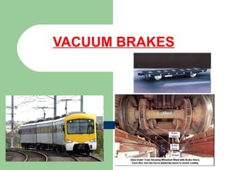
  • 2. PRESENTED BY: Shanu kumar UNDER THE GUIDANCE OF Dr.E.Basavaraj Professor JAWAHARLAL NEHRU NATIONAL COLLEGE OF ENGINEERING Department of Mechanical Engineering A Technical Seminar On “VACUUM BRAKES”
  • 3. CONTENTS 1 INTRODUCTION 2 PRINCIPLE 3 BLOCK DIAGRAM OF VBS 4 PARTS 5 WORKING OF VBS 6 BRAKE VALVE OPEN/CLOSE 7 BRAKE RELEASED/APPLIED 8 ADVANTAGE 9 LIMITATIONS
  • 4. WORLING PRINCIPLE: . The vacuum brake system is controlled through a brake pipe connecting a brake valve in the driver's cab with braking equipment on every vehicle. The operation of the brake equipment on each vehicle depends on the condition of a vacuum created in the pipe by an ejector or exhauster. The ejector, using steam on a steam locomotive, or an exhauster, using electric power on other types of train, removes atmospheric pressure from the brake pipe to create the vacuum.
  • 6. PARTS  Exhauster: It is usually controlled from the driver's brake valve, being switched in at full speed to get a brake release or at slow speed to maintain the vacuum.  Brake Block: This is the friction material which is pressed against the surface of the wheel tread by the upward movement of the brake cylinder piston.  Vacuum Reservoir: The operation of the vacuum brake lies on the difference in pressure between one side of the brake cylinder piston and the other. In order to ensure there is always a source of vacuum available to operate the brake, a vacuum reservoir is provided on, or connected to the upper side of the piston.
  • 7. PARTS  Brake Pipe: The vacuum-carrying pipe running the length of the train, which transmits the variations in pressure required to control the brake. It is connected between vehicles by flexible hoses, which can be uncoupled to allow vehicles to be separated.  Ball Valve: The ball valve is needed to ensure that the vacuum in the vacuum reservoir is maintained at the required level.
  • 9. BRAKE VALVE IS OPEN  In a vacuum brake system, depressing the brake pedal opens a valve between the power cylinder, which contains a piston, and the intake manifold to which the power cylinder is connected.  When you apply the brakes, air is exhausted from the cylinder head of the piston. At the same time, atmospheric pressure acts on the rear side of the piston to exert a powerful pull on the rod attached to the piston .
  • 10. BRAKE VALVE IS CLOSED  When the brake valve is closed, the chamber ahead of the piston is shut off from the intake manifold and is opened to the atmosphere.  The pressure is then the same on both sides of the piston; therefore, no pull is exerted upon the pull rod.  The brakes are released and the piston returned to its original position in the power cylinder by the brake shoe return springs.
  • 12. WHEN BRAKE IS RELEASED  This diagram shows the condition of the brake cylinder, ball valve and vacuum reservoir in the release position. The piston is at the bottom of the brake cylinder. Note how the brake cylinder is open at the top so that it is in direct connection with the vacuum reservoir.  A vacuum has been created in the brake pipe.  The removal of atmospheric pressure from the system has caused the ball valve to open the connection between the vacuum reservoir and the brake pipe.  The fall of the piston to the bottom of the brake cylinder causes the brake blocks to be released from the wheels.
  • 14. BRAKE IS APPLIED  During the brake application, the vacuum in the brake pipe is reduced by admitting air from the atmosphere. As the air enters the ball valve, it forces the ball (in red in the diagram above) upwards to close the connection to the vacuum reservoir.  This ensures that the vacuum in the reservoir will not be reduced.  At the same time, the air entering the underside of the brake cylinder creates an imbalance in the pressure compared with the pressure above the piston.  This forces the piston upwards to apply the brakes.
  • 15. ADVANTAGE  simple in design  Ability to get partial release, something the pneumatic brake could not do without additional equipment.  Greater amount of safety because the vacuum losses.  Highly reliable in the case of rail wagons.  Permits the automatic application of brakes down the entire length of the train from a simple control in the driver’s hand.
  • 16. LIMITATIONS  a very large brake piston and cylinder are required to generate the force necessary on the brake blocks  The existence of vacuum in the train pipe can cause debris to be sucked in.  The vacuum brake was not as effective as the air brake, it taking longer to apply and requiring large cylinders to provide the same brake effort as the air brake. It was also slow to release and requires additional equipment to speed up its operation.
  • 17. CONCLUSION :-  The vacuum brake was, for many years, used in place of the air brake as the standard. Because vacuum brake has the advantage of being simple in design and of having the ability to get a partial release, something the air brake could not do without additional equipment. The vacuum brake was not as effective as the air brake, it taking longer to apply and requiring large cylinders to provide the same brake effort as the air brake. It was also slow to release and requires additional equipment to speed up its operation. The vacuum brake can be apply automatic