Functionalized Ceramic Membranes for the Separation of Organics from Raw Water and Methods of Filtration Using Functionalized Ceramic Membranes - US20140197103
Similar to Functionalized Ceramic Membranes for the Separation of Organics from Raw Water and Methods of Filtration Using Functionalized Ceramic Membranes - US20140197103
Similar to Functionalized Ceramic Membranes for the Separation of Organics from Raw Water and Methods of Filtration Using Functionalized Ceramic Membranes - US20140197103 (20)
Functionalized Ceramic Membranes for the Separation of Organics from Raw Water and Methods of Filtration Using Functionalized Ceramic Membranes - US20140197103
1. US 20140197103A1
(19) United States
(12) Patent Application Publication (10) Pub. No.: US 2014/0197103 A1
Votaw et al. (43) Pub. Date: Jul. 17, 2014
(54)
(71)
(72)
(73)
(21)
(22)
FUNCTIONALIZED CERAMIC MEMBRANES
FOR THE SEPARATION OF ORGANICS
FROM RAW WATER AND METHODS OF
FILTRATION USING FUNCTIONALIZED
CERAMIC MEMBRANES
Applicant: Lance Energy Services, LLC, Houston,
TX (US)
Inventors: Waymon R. Votaw, Sugar Land, TX
(US); Jacob L. Davis, Houston, TX
(US); Edward E. Munson, Livingston,
TX (US); Andrew Barron, Houston, TX
(US); Samuel J. Maguire-Boyle,
Houston, TX (US)
Assignee: Lance Energy Services, LLC, Houston,
TX (US)
Appl. No.: 14/084,195
Related U.S. Application Data
(60) Provisional application No. 61/868,133, ?led onAug.
21, 2013, provisional application No. 61/728,574,
?led on Nov. 20, 2012.
Publication Classi?cation
(51) Int. Cl.
B01D 71/02 (2006.01)
C02F 1/44 (2006.01)
(52) U.S. Cl.
CPC .. B01D 71/02 (2013.01); C02F 1/44 (2013.01)
USPC ..................... .. 210/639; 210/500.26; 210/650
(57) ABSTRACT
Components, systems, and methods for producing highly
hydrophilitic, functionalized inorganic ?ltration membranes,
pre-treating organic and biological-containing waste waters
for minimal membrane fouling and scaling when processed
using such functionalized membranes, and use of such func
tionalized membranes of the present invention in ?ltration
systems for separating such pre-treated waste waters, all With
respect to optimal permeate production rates, purity of per
meate and resistance to fouling and scale formation on the
membranes.Filed: Nov. 19, 2013
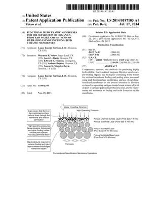
Water Crossflow Direction
Cake layers that form on H
the membrane surface
reduce flows through the l l
membrane and reduce .. .0
permeation
High operating pressures
faces organics, biologicals
and other fouling bodies
into the pore spaces
reducing permeate flows
Back pressure required to
remove fouling and cake
layers weakens/dislodges
membrane layers
Permeate
%{}{}
igh Operating Pressure
Porous Channel Surface Layer (Pore Size 1-5 nm)
Porous Substrate Layer (Pore Size 5-100 nm)
Porous Substrate Layer
Pore Size 0.1-1.5 Microns)
Porous Substrate Base Layer
(Pore Size 5-10 Microns)
Conventional Nanofiitration Membrane Operations
2. Patent Application Publication Jul. 17, 2014 Sheet 1 0f 13 US 2014/0197103 A1
OH
Hoff OHH N
2 1 O
O OH O OH O OH
3,5-Dii0d0tyrosine Trans-fumaric Acid Malonic Acid
HO
5/;0
HZN
O OH O OH O OH
Cysteic Acid Octanoic Acid Stearic Acid
OH
HO OH
O OH O OH
3,5-Dihydroxybenzoic Acid Para-hydroxybenzonic Acid
FIG. 1
15. US 2014/0197103 A1
FUNCTIONALIZED CERAMIC MEMBRANES
FOR THE SEPARATION OF ORGANICS
FROM RAW WATER AND METHODS OF
FILTRATION USING FUNCTIONALIZED
CERAMIC MEMBRANES
CITATION TO PRIOR APPLICATION
[0001] Applicant claims priority for purposes ofthis appli
cation to Provisional US. Application Ser. Nos. 61/868,133,
?led 21 Aug. 2013, and 61/728,574, ?led 20 Nov. 2012, from
which priority is also claimed under 35 U.S.C. §119(e) for
purposes related to United States ofAmerica patent protec
tion.
BACKGROUND OF THE INVENTION
[0002] 1. Field of The Invention
[0003] The present invention pertains to apparatuses and
methods for separation of constituents of a multi-constituent
liquid solution or suspension.
[0004] 2. Background Information
[0005] Developing methods and apparatus for separating
organics (oil & greases, and biological materials) from raw
water streams is important in many industries, including the
oil & gas industry. The term “raw waters” is an industry term
for describing waste-containing waters and is used hereafter
to refer to any water that requires treatment, including but not
limited to industrial, agricultural, domestic andpotable water.
[0006] Whether simply considering environmental issues,
or costs and effectiveness in complying with associated regu
lations and best practices, separating contaminants from raw
waters is ofincreasing importance for 1) oil and gas industry
?ow-back water from hydraulic fracturing; 2) oil and gas
industry produced water that ?ows from the wells during the
production of oil and/or gas; 3) raw waters generated in the
processing of food (e.g., meat and poultry); 4) sea water
contaminated with oils and greases and biological materials;
5) municipal water supplies; and others.
[0007] Separating solids from liquids is nothing newiit
has been practiced in various forms for hundreds of years.
However, various new processes, devices and materials have
been suggested during the past few decades in the never
ending quest for more effective and/or more ef?cient and
cost-effective ?ltration methods and systems.
[0008] One widely accepted separation method involves
Aluminum polymers, such as poly-aluminum hydroxychlo
ride (also known as aluminum chlorohydrate orACH), poly
aluminum chloride (PAC), or poly-aluminum siloxane sulfate
(PASS). These polymers are often chemically combined with
quaternized polymers, such as di-allyl di-methyl ammonium
chloride (DADMAC), and are added to water to create ?oc
culent materials that can be removed by skimming or ?ltra
tion.
[0009] In recent years, membrane ?ltration has been shown
to be one ofthe best methods for large-scale separation ofraw
water. Processing factors, such as recyclability ofthroughput
material in cross ?ow membrane assemblies, ease of clean
ing, as well as highly pure permeate with no chemical tainting
are among the attractive features of this approach. A signi?
cant drawback of membrane puri?cation, however, is mem
brane fouling. Fouling can arise from a number of factors,
such as adsorption inside the membrane, deposition on the
membrane surface to form a cake layer, and blocking of the
membrane pores.
Jul. 17, 2014
[0010] Membranes with hydrophilic surfaces have exhib
ited more desirable anti-fouling properties than more hydro
phobic (less hydrophilic) membranes. It is envisioned that
such properties are due to hydrophilic membranes being less
sensitive to adsorption. However, industry has yet to achieve
a suitably hydrophilic membrane that also meets other nec
essary or desirable performance characteristics. Prior
approaches have concentrated on either fabricating mem
branes from hydrophilic polymers, or attaching high molecu
lar weight hydrophilic materials to inorganic membranes.
[0011] This latter category of approaches includes surface
segregation, surface coating, and surface graft polymeriza
tion. However, many of these methods have limitations that
the present inventor now can show are avoidable. For
instance, ceramic membranes offer good commercializable
methods for separation. However, currently available ceramic
membranes require very small pores (550 nm) for hydrocar
bon/water separation. Such small pore sizes tend to decrease
?uid ?ow rate and promote clogging. Furthermore, typical
ceramic membranes are readily fouled by biological material
from viruses, bacteria, and proteins. Attempts to overcome
these small-pore issues results in other problems, including
requirements for high ?ow rate pressures (involving higher
equipment costs and energy consumption), or the need for
less effective, much larger membrane pores. In any event,
fouling still occurs through use ofcurrently available ceramic
membranes at rates now known by the present inventor to be
avoidable through cost-effective and otherwise ef?cacious
means. With fouling comes low net permeate rates, require
ments for back-?ushing of the permeate to clear the mem
brane, and often a shortened service life of the membrane
(with associated elevated costs).
[0012] One manifestation ofthe present invention involves
using membranes fabricated (at least partially) of silicon car
bide (sometimes hereafteri“SiC”). SiC-based embranes
have been studied in some detail with respect to their inherent
hydrophobicity and hydrophilicity, and currently are found
lacking. This is the result ofinherent characteristics ofthe SiC
substrate, wherein Si-terminated surfaces tend to be hydro
philic, and C-terminated surfaces are more hydrophobic. The
net effect is that current industrial silicon carbide membranes
and alumina based membranes have only a mild hydrophilic
ity, with a high degree of hydrophilicity being a more desir
able, but currently-lacking characteristic.
[0013] University researchers who developed carboxylic
acid functionalization of some oxide based substrates (e.g.,
aluminum oxide) have, as recently as 2012, indicated a dis
belief in the desirability of functionaliZing other inorganic
materials (including silicon carbide) in achieving enhanced
hydrophilicity because ofa lack ofhydroxyl terminations for
the required covalent bonding. Similarly, a global supplier of
tubular ceramic membranes recommended alumina, Zirconia,
or titania-based ceramics for the use in treating the herein
described raw waters because ofpoor performance of silicon
carbide in past oil and gas water treatability studies.
[0014] Therefore, while there is a compelling need to
develop ever-more ef?cacious and cost-effective ?ltration
systems and methods, and particularly ones that reduce or
eliminate the present approaches’ limitations of requiring
multiple, time-consuming steps; high equipment costs; and
signi?cant energy consumption, it is clear that conventional
wisdom teaches away from the materials and methods ofthe
present invention that (as described below) achievesjust such
objectives. Such objectives are achieved involving one fea
16. US 2014/0197103 A1
ture ofthe very approach dismissed in the prior art: maximiz
ing the hydrophilicity of silicon carbide-based reactant sur
faces of a ?ltration membrane through the functionalization
ofsilicon carbide to maximize the hydrophilicity and provide
organophobic performance.
[0015] Practice of the present invention that reduces the
number of steps, or time consumed by steps in effective
?ltration, is most cost effective per unit volume ofprocessed
raw waters, and/or reduces energy consumption associated
with ?ltration will substantially bene?t industry, as well as
society at-large. Some bene?ts from such improved ?ltration
may be apparent (direct operating costs savings, reduction in
capital expenditures, reductions in labor costs, removing
“choke points” in processes that involve ?ltration, and so on).
However, other, less apparent bene?ts arise as well. For
example, when ?ltration can be achieved cheaper, faster, with
less labor requirements, and with simpler and/or smaller sys
tems, many economic and practical barriers to the utilization
of?ltration systems andmethods are substantially reduced. In
many instances, this translates into higher levels of compli
ance with environmental regulations and associatedreduction
in overall environmental impact from many industrial pro
cesses.
[0016] As is describedbelow, practice ofthe present inven
tion affords the opportunity to meet, notjust one, but all ofthe
objectives of achieving optimal ?ltration of raw water by
reducing direct operating costs, reducing capital expenditures
for ?ltration systems, reducing labor costs, and removing
“choke points” in processes that involve ?ltration (by accel
erating the ?ltration process for a unit volume of raw water,
when compared to conventional systems and methods).
BRIEF DESCRIPTION OF THE DRAWINGS
[0017] FIG. 1 depicts summaries ofreaction conditions for
carboxylic acid functionalization of alumina surfaces.
[0018] FIG. 2 depicts comparative wettability offunction
alized alumina coated wafers using various reagents.
[0019] FIG. 3 provides a general depiction ofthe function
ality of cross-?ow membrane function (including that
thought to be optimal for use of the ?ltration membranes of
the present invention).
[0020] FIG. 4 depicts the general structure of a ?ltration
membrane.
[0021] FIG. 5 depicts test results for permeate ?ow under
the four scenarios, wherein the open circle represents func
tionalized pure water (DI) baseline, open square represents
non-functionalized pure water (DI) baseline, solid circle rep
resents functionalized membrane performance on raw water
and solid square represents non-functionalized performance
on like raw water.
[0022] FIG. 6 depicts data showing total petroleum hydro
carbon quantity data from the ?ow back water feed sample.
[0023] FIG. 7 depicts data showing total petroleum hydro
carbon quantity in a water permeate sample.
[0024] FIG. 8 depicts a cross-?ow systems as is useful in
conjunction with the present invention.
[0025] FIG. 9 depicts a representative comparison offunc
tionalizedmembranes without pretreatment (the lowery-axis
and shorter x-axis graph line) and with the use of pH adjust
ment and the addition of a scale inhibitor (HEDP phospho
nate in the test shownithe upper y-axis, longer x-axis graph
line).
Jul. 17, 2014
[0026] FIG. 10 depicts the ?ow characteristics of liquid
though a ?ltration membrane as an example ofpractice ofthe
present invention.
[0027] FIG. 11 depicts a exemplary system design for the
?ow treatment method of membrane functionalization.
[0028] FIG. 12 depicts the process ?ow diagram of a sys
tem such as is depicted in FIG. 11.
[0029] FIG. 13 depicts data from conductivity tests for
determining degree of application of reagents to ?ltration
membranes.
DETAILED DESCRIPTION OF THE PREFERRED
EMBODIMENT
[0030] To address the problems above, the present inven
tion includes producing and using ?ltration membranes that
are of an organophobic and highly hydrophilic nature. Such
membranes are further characterized as having at least some
surface areas that include porous, hydroxyl terminated sub
strates of inorganic materials and that are functionalized by
hydrophilic molecules through a novel and unobvious pro
cess to achieve both a product conventionally thought not to
be feasible (or even desirable), and one that exceeds all rel
evant performance parameters relevant to ?ltration or sepa
ration processes involving raw waters (or other “multi-con
stituent ?uids”). Filtration membranes produced and used in
accordance with the present invention resist fouling to a far
greater degree than any known ?ltration membrane, while
providing superior separation performance.
[0031] Filtration membranes of the current invention gen
erally include: (1) a series of channels through which the
waste stream ?ows, the size and shape ofthese channels being
conventionally chosen based upon desired viscosity and ?ow
rate characteristics; (2) a series of pores with pore sizes of
0.04 micron in diameter and larger; (3) surfaces ofthe mem
brane being functionalized by carboxylic acid(s); and (4) the
respective substituent group of the carboxylic acid(s) being
chosen to create a hydrophilic surface (e.g., cysteic acid,
malonic acid).
[0032] Onepreferredmanifestationofthepresent invention
involves carboxylic acid as the hydrophilic agent associated
with the ceramic. In some applications, the carboxylic acid
has the general formula RCOZH, where R is a hydrophilic
functional group. Exemplary carboxylic acids include, with
out limitation, cysteic acid, 3,5-diiodotyrosine, trans-fumaric
acid, malonic acid, octanoic acid, stearic acid, 3,5-dihydroxy
benzoic acid, parahydroxy benzoic acid, and combinations
thereof. Ofthese, cysteic acid is currently thought to be opti
mal.
[0033] Contact angle measurements for a range ofcarboxy
lic acids functionalized onto alumina coated silicon wafers
were investigated to determine the functionalization that
results in the most hydrophilic surfaces. Using a modi?cation
of the literature method (C. T. Vogelson, A. Keys, C. L.
Edwards, and A. R. Barron, Molecular coupling layers
formed by reactions ofepoxy resins with self-assembled car
boxylate monolayers grown on the native oxide ofaluminum,
J. Mater. Chem., 13 (2003) 291-296), silicon wafers were
coated with a thin layer of alumina (100 nm) via e-beam
deposition. In order to remove impurities on the alumina
surface, the coated wafers were dipped in a 1:1 solution of
conc. H2SO4 and 30% HZO2 for 5 min. The wafer was then
washed with 2-propanol and air dried. The alumina coated
silica wafer was then gently re?uxed at various temperatures
depending on the functionalizing carboxylic acid. After the
17. US 2014/0197103 A1
reaction was completed, the wafers were washed with IPA
and air dried. Table 1 below and FIG. 1 provide summaries of
reaction conditions for carboxylic acid functionalization of
alumina surfaces.
TABLE 1
Summary ofreaction conditions for carboxylic acid
functionali ati on of alumina surfaces.
Vol— Molar— Temper— Reac—
Mass ume ity ature tion
Carboxylic acid (g) Solvent (mL) (M) (O C.) time (h)
3.5— 1.87 DMSO 20 0.1 160 24
diiodotyrosine
trans—fumaric 2.32 EtOH 40 0.5 60 24
acid
malonic acid 2.08 H20 40 0.5 105 24
cysteic acid 3.74 H20 40 0.5 105 24
octanoic acid 2.90 DMSO 40 0.5 160 24
stearic acid 1.14 CHCl3 40 0.1 61 24
3.5— 3.08 DMSO 40 0.5 160 24
dihydroxybenzoic
acid
para— 2.76 DMOS 40 0.5 160 24
hydroxybenzoic
acid
[0034] The surfaces were tested using goniometer contact
angle techniques. From this it was observed that cysteic acid
functionalized alumina coated wafers were extremely hydro
philic, achieving complete wettability when in contact with
water. See FIG. 2
[0035] In practice ofthe present invention the advantage of
the carboxylic acid functionalization of the ceramic surface
lies in its stability towards the kinds ofraw waters described
herein to be treated. Particularly advantageous ofcarboxylic
acid attachment is its stability across a wide temperature
range. This range would be inclusive of those raw waters
expected from the highly signi?cant sector of raw waters
produced though hydraulic fracturing, with raw water tem
peratures reaching 140° F.
[0036] The ceramic membranes can be reacted with a wide
range ofhydrophilic molecules. Thus far, the present disclo
sure has focused on the use of carboxylic acids as the hydro
philic molecule for functionalization of the membrane, and
examples provided herein focus on such species ofthe present
invention. However, alternative ligands from the classes of
zwitterionic molecules, phenyl amines, phenyl amidines
(e.g., 1,3-diphenylamidine), and amino pyridines (e.g.,
methylaminopyridine) all have been shown to form bridging
complexes with Group 13 metals (e.g., aluminum, gallium
and indium). The inventors have demonstrated functionaliza
tion with carboxylic acids (e.g., cysteic acid) on aluminum
oxide and silicon based surfaces (e.g., silicon carbide) with
like e?icacy. Aluminum oxide and silicon substrates (e.g.,
silicon oxide, silicon carbide) share similar atomic structures
(i.e., atom-atom distances), structural characteristics (i.e., lat
tice constants) and have been shown to be within the bridging
distance of the functionalizing ligand. With the bridging or
capping distances known of target ligands of the classes of
zwitterionic molecules, phenyl amines, phenyl amidines, and
amino pyridines appropriate linkage moieties can be chosen
considering materials availability and costs and functional
behavior. Target ligands of the classes of zwitterionic mol
ecules, phenyl amines, phenyl amidines, and amino pyridines
Jul. 17, 2014
may be acceptable alternatives to using carboxylic acids as
the functionalization ligand in lieu of or in combination with
carboxylic acids.
[0037] A general depiction of the functionality of cross
?owmembrane function (includingthatthought to be optimal
for use ofthe ?ltration membranes ofthe present invention),
as well as ofthe overall ?ltration membrane structure itselfis
provided in FIGS. 3 and 4. The geometries, number of chan
nels, pore sizes, etc. can be altered to tune the membrane to
raw water viscosities and desired ?ow rates, according to
conventional manner.
[0038] Ceramic membranes may be derived from various
sources, with the preferred membranes for use in conjunction
withthe present inventionhaving at least some silicon carbide
reactant surfaces (the surfaces that will be treated according
to the present invention and will ultimately come into contact
with in-process raw waters). Reactant surfaces of other inor
ganic, oxidizable materials may include silicon dioxide
(SiOZ), silicon nitride (Si3N4), Si-rich silicon nitride (SiXN4),
etc.
[0039] To functionalize the SiC membranes, the SiC sur
faces must be modi?ed to have a high fraction of surface
silanols (SiOH). Stable monolayers can be formed with sur
face chemistry where the material to be functionalized pre
sents stable hydroxyl groups at the surface. Silicon dioxide,
silicon nitride and silicon carbide will have a degree ofnatural
surface oxidation in the form ofnative silicon dioxide, silicon
oxynitride or silicon oxycarbide. Prior research indicates that
silanol densities range empirically from 4.5 free surface sil
anols/nm2 (fully hydrated amorphous silica) to 4.6 silanols/
nm2 (fully hydrated silica surface). This aspect ofthe present
invention focuses on the maximization of surface hydroxyl
groups by surface oxidation and protonation of the surface
oxides to allow for self-assembling monolayers of hydro
philic molecules (non-limiting examples ofsuch hydrophilic
molecules include carboxylic acids, zwiterrionic molecules,
phenyl amines, phenyl amidines, amino pyridines, and com
binations thereof). The currently thought optimal suchhydro
philic agent is cysteic acid.
[0040] Functionalization accordingto the present invention
is accomplished through: 1) surface thermal or chemical oxi
dation ofthe SiC substrate (e.g. thermal or plasma treatments
in air or oxygen, HzOZ/H2804) for cleaning the surface of
organic contamination and for hydroxyl generation, 2) acidi
?cation for monolayer stability, and 3) contact ofthe hydro
philic molecule (preferentially cysteic acid in aqueous solu
tion).
[0041] The present inventor validated this methodology by
using porous silicon carbide aeration stones to determine the
organic rejection capability ofthe functionalized silicon car
bide. To chemically oxidize the surface, a 35% HZSO4z35%
H202, (4:1) “piranha” solution was used with a contact time
of23 hours and 50 minutes. The oxidation was accomplished
at ambient temperature, in a ?xed volume container with
intermittent manual push ofthe piranha solution through the
porous silicon carbide ?ow channels with a syringe.
[0042] The monolayerhydrophilic molecule chosen forthe
surface functionalization was cysteic acid. The aqueous cys
teic acid has the dual value ofprotonating the oxidized silicon
carbide surface forhydroxyl formation and delivery ofhydro
philic molecules for self-assembling, covalent, monolayer
functionalization. The functionalization was accomplished at
ambient temperature, in a ?xed volume container with inter
18. US 2014/0197103 A1
mittent manual push ofthe aqueous cysteic acid through the
porous silicon carbide ?ow channels with a syringe.
[0043] The functionalization of the prepared SiC surfaces
followed over a period of 74 hours and 25 minutes, with
intermittent manual push of solution through the membrane.
The measurements at time 0 were pH 1.98, conductivity of
15.12 mS, and temperature of 17.6 C. The functionalization
was complete at approximately 50 hours and 25 minutes as
determined through rate of change of conductivity with
respect to time approaching zero. Functionalization can be
validated additionally with contact angle determination. The
measurements at 50 hours and 25 minutes were pH 1.99,
conductivity of 10.39 mS, and temperature of 18.6 C. The
membrane was retained in the aqueous cysteic acid for an
additional 24 hours to maximize monolayer surface coverage.
At endpoint (74 hours and 25 minutes), the measurements
were pH 1.99, conductivity of 10.45 mS, and temperature of
18.4 C.
[0044] The determination of membrane performance was
performed with a sequential, comparison of ?ow rates of a
membrane with no functionalization with one functionalized
with cysteic acid. The water tested was provided from a ?ow
backbattery servingmultiple hydraulic fracturing wells inthe
Permian Basin, WolfCamp strata. The apparatus for testing
was a dead-end, gravity feed vessel that was used to deter
mine time required to permeate 200 mL of sample from a
repeated known head/feed volume. The captured 200 mL
volume over the time required time to permeate the volume
was converted to permeation quantity (Qp) in mL/minute.
This was performed with deionized (DI) water for pure water
Qp baseline determination for both the functionalized and
un-functionalized membranes. Additionally, this was per
formed with oil and gas ?ow back water (O&G water) for Qp
determination for both the functionalized and un-functional
ized membranes over a 2 hour period.
[0045] The results for permeate ?ow under the four sce
narios is shown in FIG. 5, wherein the open circle represents
functionalized pure water (DI) baseline, open square repre
sents non-functionalized pure water (DI) baseline, solid circle
represents functionalized membrane performance on raw
water and solid square represents non-functionalized perfor
mance on like raw water.
[0046] As shown in FIG. 5, the un-functionalized mem
brane exhibited a steady decline in performance following
initial solids loading and due to organic fouling ofthe mem
brane pore space. The ?nal O&G water ?ow rate Qp was
50.8% of the pure water (DI) baseline. The functionalized
membrane exhibited some initial decline in performance
attributable to solids loading, but maintained a steady ?ow
rate Qp for the majority of the test (91.0 mL/min average),
providing a much-improved performance of 80.5% of the
pure water (DI) baseline.
[0047] Total Petroleum Hydrocarbon quantity data from
the ?ow back water feed sample is shown in FIG. 6, while
Total Petroleum Hydrocarbon quantity in the water permeate
sample is shown in FIG. 7.
[0048] The functionalized membrane exhibited a high
organics rejection capability despite having a very large pore
size distribution (pore sizes range extended up to 10 micron
and larger). The rejection rate ofTotal Petroleum Hydrocar
bons was 85.4%. Similarly, the functionalized membrane
rejected Oils and Greases (EPA1664A method) at a 73.1%
rate despite the large pore size. The functionalized membrane
Jul. 17, 2014
exhibited a higher solids rejection rate (visual turbidity) and
oil and grease rejection rate than the un-functionalized mem
brane.
[0049] A ?ltration membrane ofthe present invention may
be used in a cross?ow system, which is thought to be the
optimal context of such use. A porous cross?ow ceramic
membrane system of the present invention will generally
include: (1) a series of channels through which the waste
stream ?ows, the size and shape of these channels being
chosen based upon viscosity and ?ow rate requirements; (2) a
series ofpores withpore sizes of0.04 microns in diameter and
larger; (3) the surface of the membrane functionalized by
carboxylic acids; and (4) the substituent group ofcarboxylic
acid chosen to create a hydrophilic surface (e.g., cysteic acid,
malonic acid) that inhibits fouling ofthe membrane.
[0050] As illustrated in FIG. 8, a cross?ow system itself
will generally included: (1) the above-described, functional
ized ceramic membranes; (2) membrane housings that pro
vide the separation ofconcentrate and permeate streams from
the feed to the system; (3) pump(s) with capacity for recircu
lating the raw water within the system and for feeding water
from concentration tank(s) to the system; and (4) a controller
that monitors ?ow rate, and physical and chemical properties
ofthe waste stream, permeate, and concentrate.
[0051] In operation, raw waters containing organic com
pounds ?ow through housings in the cross?ow system. This
results in the retention oforganic compounds and/or biologi
cal materials in the concentrate and the release ofthe perme
ate. This, in turn, results in the puri?cation of the raw water
sample through separation. In practice, the organophobic
properties of the functionalized membranes have produced
separationrates of>97% ofthetotal petroleumhydrocarbons,
oils & greases, and biological compounds from the raw water
samples.
[0052] The permeate stream has been veri?ed empirically
to contain soluble and miscible ions, elements, and com
pounds, but is generally free of suspended solids and organic
compounds (not including low molecular weight soluble
organic compounds). In some embodiments the concentra
tion ofthe organic compounds and/or biological matter in the
concentrate may be large due to recycling the concentrate
through the membrane channels for a second (or multiple)
times.
[0053] Overall, the systems, membranes, and methods of
the present invention can be utilized to reduce the carbon
content of various raw waters. Such results provide various
advantages over the systems, membranes, and methods ofthe
prior art. For instance, the experimental data shows that the
use of ceramic membranes of the present invention reduces
the pump pressure required (relative to non-functionalized
membranes) for a particular ?ux from about 6-7 bar to about
0.25-2.0 bar. More importantly, reduction of fouling allows
the membranes to perform at a steady state over time with
minimized need for back-pulsing or ?ushing.
[0054] Empirical analysis ofthe performance ofthe mem
branes in a cross?ow con?guration such as described has
allowed the determination of optimal ranges of operation for
both water velocity through the membranes and the trans
membrane pressure required to maximize permeate produc
tion. These parameters can be controlled independently to
optimize the performance ofthe systems. For example, veloc
ity is controlled by the circulation pump that continually
circulates the raw water through the housings. Empirical data
has shown that the permeate production (and ?ux rates) are
19. US 2014/0197103 A1
optimal in control schemes where the pressure drop is mini
mized through the membranes balanced against maintaining
good mass ?ow of the clean water portion of the raw water
through the membranes.
[0055] Data from testing on multiple raw waters has shown
that velocities in the range of 2.4 to 3.5 meters per second
produce optimal permeate ?ow for the range of raw waters
tested.
[0056] Similarly, trans-membrane pressure has been opti
mized within the systems to achieve optimal permeate pro
duction rates. Trans-membrane pressures are balanced
between suf?cient pressure to drive permeate ?ow through
the membranes yet low enough to reduce the motive force on
colloidal foulants to avoid the buildup ofexcessive solids that
would reduce permeate ?ow. Empirical data over multiple
raw water samples has shown that the system operates opti
mally in the 0.25 to l .0 bar range oftrans-membrane pressure
for the range ofraw waters tested. The optimization oftrans
membrane pressures is possible outside of the range above
and is dependent on the quantity and type ofsuspended solids
(colloids) in the raw water.
[0057] A ?ltration membrane ofthe current invention may
also be used in a “dead end” system. A dead end system will
be generally include: (1) functionalized ceramic membranes
as described herein; (2) dead end design membranes that
provide the separation of permeate streams from the feed
water volume in the system; (3) feed pump(s) with capacity
for supplying the raw water to the system; and (4) a controller
that monitors ?ow rate, and physical and chemical properties
of the waste stream, permeate, and concentrate.
[0058] In operation, raw waters containing organic com
pounds ?ow through dead end membranes inthe system. This
results in the retention oforganic compounds and/or biologi
cal materials in the concentrate and the release ofthe perme
ate. This in turn results in the puri?cation of the raw water
sample through separation.
[0059] Analysis ofthe performance ofthe membranes in a
dead end con?guration is conducted to determine optimal
ranges ofoperation for the trans-membrane pressure required
to maximize permeate production relative to back-washing
frequency intensity. As with use in the cross?ow system con
text, the permeate stream has been veri?ed empirically to
contain soluble andmiscible ions, elements, and compounds,
but is generally free of suspended solids and organic com
pounds (not including low molecular weight soluble organic
compounds). In some embodiments the concentration of the
organic compounds and/or biological matter in the concen
trate may be large due to increasing concentration in the feed
tank volume over time.
[0060] Advantages afforded by the present invention, not
availablethroughuse ofsystems, membranes, andmethods of
the prior art, further include the reduction of fouling. This
facilitates membranes performing at a steady state over time
with minimized need for back-pulsing or ?ushing.
[0061] The functionalized membrane of the present inven
tion exhibits dramatic improvements in the rejection of
organics (biological and oils and grease), but is susceptible to
scaling and colloidal fouling as would be an un-functional
ized membrane. Reversal of membrane fouling is accom
plished with the functionalized membranes in a manner con
sistent with industry practice to include use of acids, bases
and surfactants.
Jul. 17, 2014
[0062] Conventional ?ltration membranes are susceptible
to the following sources offouling, with the related bene?t of
the ?ltration membranes ofthe current invention being shown
in conjunction therewith:
[0063] 1. Biological foulants such as bacteria and
virusesi?ltration membranes of the current invention
reject biological foulants, resulting in a dramatically
reduced rate of fouling
[0064] 2. Hydrocarbon foulants such as oils and
greasesi?ltration membranes of the current invention
reject organics, resulting in a dramatically reduced rate
of fouling
[0065] 3. Colloidal foulants such as particulates or sus
pended solidsi?ltration membranes of the current
invention are resistant to colloidal fouling due to the
establishment ofa waterboundary layer that protects the
membrane surface. However, the invention membranes
must be operated to optimize velocities and trans-mem
brane pressures (as described above in the description of
a cross?ow system involving the present invention) to
maximize the permeate ?ow through the minimization
of colloidal fouling layers formed on the membrane
channels.
[0066] However, scaling (such as carbonate or sulfate
scales) is just as much of a problem for the functionalized
membranes ofthe present invention as for conventional mem
branes, and requires the pretreatment ofraw waters to prevent
the deposition of scale on the membrane surface and within
the pore space of the membranes.
[0067] A pretreatment process can be generalized as fol
lows:
[0068] 1. Testing the water chemistry ofthe raw waters to
be separated,
[0069] 2. Modeling the raw waters to determine the satu
ration levels of the water/ionic content, solids content,
level of total organic carbon, amount of oils & greases,
etc.,
[0070] 3. Determination of the type and dosage rate of
scale inhibitors required for the raw water (e.g., to con
trol supersaturated Barite-BaSO4),
[0071] 4. Determination of pH adjustment required to
control for soluble scales (e.g., Calcium Carbonate
CaCO3),
[0072] 5. Determination of oxidant type and dosage rate
to remove Iron and other soluble metals, and
[0073] 6. Determination of the pretreatment plan to
include dosing sequences and mixing requirements.
[0074] The alkaline earth cations, Mg2+, Ca2+, Ba2+, Sr2+,
are the predominant divalent metal ions in produced brines in
the oil and gas industry. Divalent metals are also prevalent in
mining, groundwater and other raw waters requiring treat
ment. Scale inhibition can be accomplished with phosphates,
phosphonates, polyphosphonic acid, acrylates, polyacrylates,
or by other additives that chelate the metal ions or inhibit the
formation ofscaling crystals or foul the crystals to retard their
growth. The determination of scale risks is accomplished
with geochemistry models available to the industry including
“SCALESOFTPITZER”, “PHREEQC” INTERACTIVE
218.3670, and others. Sample saturationindices output from
Phreeqc Interactive are shown below:
20. US 2014/0197103 A1
Phase SI log IAP log KT
Anhydrite —0.99 —5.34 —4.35 CaS04
Aragonite —0.22 —8.53 —8.31 CaC03
Barite 1.81 —8.23 —10.03 BaS04
Calcite —0.07 —8.53 —8.46 CaC03
Celestite 0.12 —6.51 —6.62 SrS04
Dolomite —0.48 -17.48 -17.00 CaMg(C03)2
Fe(OH)3(a) 0.26 5.15 4.89 Fe(OH)3
Goethite 6.03 5.17 —0.86 FeOOH
Gypsum —0.80 —5.38 —4.58 CaS04: 2H20
Halite —1.56 0.01 1.57 NaCl
Hausmannite —22.43 39.58 62.01 Mn304
Hematite 14.08 10.37 —3.71 Fe203
Manganite —8.81 16.53 25.34 Mn00H
Melanterite —5.31 —7.56 —2.26 FeS04: 7H2O
Pyrochroite —8.72 6.48 15.20 Mn(0H)2
Pyrolusite —15.44 26.58 42.01 Mn02
Rhodochrosite —1.23 —12.35 —11.12 MnC03
Siderite 0.27 —10.59 —10.87 FeC03
Smithsonite —3.80 —13.75 —9.96 ZnC03
Strontianite —0.43 —9.70 —9.27 S1C03
Sulfur —39.63 —34.66 4.97 S
Witherite —2.85 —11.42 —8.57 BaC03
[0075] Interpretation ofthe models to determine supersatu
ration risks and means of management is conducted prior to
the full scale processing of raw waters.
[0076] Scales have been successfully inhibited with the use
of available chemicals (including polyacrylates, phospho
nates) to prevent scale formation and allow the functionalized
membranes to perform as intended in the rejection oforganics
(hydrocarbons and biologicals). Dosing ofinhibitors is deter
mined based on manufacturers recommended threshold lev
els and experience.
[0077] Additionally, scales are managed by the determina
tion of the solubility products of potential sealants based on
the water chemistry of the raw water to be treated (models
used include “ScaleSoftPitzer”, “Phreeqc Interactive 2.18.3.
6670”, and others). Through determination ofthe saturation
level of ions and their related scales (e.g., aragonite, calcite,
hematite, etc.), pH can be modi?ed in the raw water to move
the raw water to a state of undersaturation for a subset of
scales in order to maintain the solubility of the ions and
prevent scales on the membrane.
[0078] A combination pH adjustment to manage solubility
and the addition of scale inhibitors effectively prevents the
formation of scales on the functionalized membrane and
allows the membrane to perform its intended purpose of
rejecting or separating organics from the raw water. A repre
sentative comparison of functionalized membranes without
pretreatment (the lower y-axis and shorter x-axis graph line)
and with the use ofpH adjustment and the addition of a scale
inhibitor (HEDP phosphonate in the test shownithe upper
y-axis, longer x-axis graph line) is shown in FIG. 9
[0079] Practice ofthe present invention optimally includes
use oftubular ceramic membranes functionalizedwith hydro
philic chemicals as described above. Multiple methods have
been tested and validated for the application of hydrophilic
molecules to the membranes.
[0080]
[0081] Tubular ceramic membranes with the application of
hydrophilic molecules by using a vacuum pump to pull a
vacuum on a vessel ?lled with the hydrophilic molecules in
solution to apply the hydrophilic molecules to a large fraction
of the membrane surface area including pore space. This
A. Vacuum Application
Jul. 17, 2014
method proves viable, but is maintenance intensive in a com
mercial setting and was found to be less cost effective.
[0082] B. Static Submersion
[0083] Designs for large scale application of the hydro
philic molecules to ceramic membranes using static submer
sion treatment were tested. This provides a viable treatment
method, but provides a lower coverage of the available sur
face area, particularly in the pore space of the membranes.
This method is effective in the partial functionalization ofthe
membranes and can be utilized in the treatment ofraw waters
that have less extreme contaminant levels and in cases of
reduced inorganic scale risk.
[0084] C. Recirculating Linear Treatment
[0085] Recirculating ?ow through the ?ow channels of
ceramic membranes has been investigated for effectiveness,
cost and commercial scalability. Recirculating linear treat
ment is accomplished by ?owing hydrophilic molecules in
solution through the ?ow channels of ceramic membranes.
This is a viable treatment methodology, but this methodology
only produces a surface treatment ofthe membrane and does
not produce a full treatment ofthe traveled path that raw water
will take inthe use ofthe membranes. This method is effective
in the partial functionalization of the membranes and can be
utilized in the treatment ofraw waters that have less extreme
contaminant levels and in cases of reduced inorganic scale
risk.
[0086] Additionally, linear treatment of multiple mem
branes in a commercial setting was performed and was found
to be effective in short duration testing.
[0087] D. Recirculating Flowing Design
[0088] The inherent ?ow characteristics of ceramic mem
branes designed for raw waters separation renders the cur
rently-envisioned, optimal functionalization method. In the
preferred method for functionalization (?ow treatment), the
hydrophilic molecules in solution are re-circulated through
the ?ow channels of the membranes but were forced to ?ow
through the pore spaces in the membrane to simultaneously
treat the internal ?ow channels, pore space, and outside diam
eter of the membranes (see FIG. 10).
[0089] By treating the totality of the membrane surface
area, the commercial effectiveness of the membrane is opti
mized by both 1) protecting all membrane surfaces that come
in contact with raw waters and the soluble fraction ofthe raw
waters, and 2) extending the useful life of the membrane
under abrasive conditions. If abrasive suspended particles
abrade the interior channel surface over time, this would
reduce the hydrophilicity of the surface treat membrane
through removal of the ceramic substrate.
[0090] In the preferred ?ow treatment method, all surfaces
in contact with waters are protected by the organophobic
boundary layer, and have increased tolerance to abrasion due
to the application of hydrophilic molecules through the
ceramic membrane substrate pore space.
[0091] The preferred system design for the ?ow treatment
method ofmembrane functionalization is generally depicted
in FIG. 11. According to this design, the reaction chemical is
pumped to the bottom of the housings on the depicted right
side of the drawing and ?owed upward through the mem
branes within the housing. The reaction chemical then ?ows
through the membrane channels and through the membrane
pore spaces to exit at the top of the membrane housing and
from the smallerperrneate return lines exiting from the side of
the housing. Upon exit fromthehousings, the reaction chemi