1. Bob Morris is a retired metallurgist/
materials scientist who has been dab-
bling in Free Flight modeling since
2005 with an interest in old timer,
Nostalgia and small gliders. He’s a
member of the Brooklyn Skyscrapers
and regular attendee at the Geneseo,
New York Great Grape Gathering.
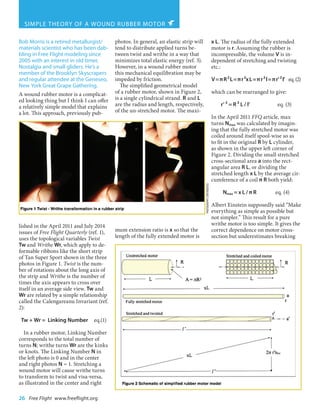
A wound rubber motor is a complicat-
ed looking thing but I think I can offer
a relatively simple model that explains
a lot. This approach, previously pub-
lished in the April 2011 and July 2014
issues of Free Flight Quarterly (ref. 1),
uses the topological variables Twist
Tw and Writhe Wr, which apply to de-
formable ribbons like the short strip
of Tan Super Sport shown in the three
photos in Figure 1. Twist is the num-
ber of rotations about the long axis of
the strip and Writhe is the number of
times the axis appears to cross over
itself in an average side view. Tw and
Wr are related by a simple relationship
called the Calengareanu Invariant (ref.
2):
Tw + Wr = Linking Number eq.(1)
In a rubber motor, Linking Number
corresponds to the total number of
turns N; writhe turns Wr are the kinks
or knots. The Linking Number N in
the left photo is 0 and in the center
and right photos N = 1. Stretching a
wound motor will cause writhe turns
to transform to twist and visa-versa,
as illustrated in the center and right
photos. In general, an elastic strip will
tend to distribute applied turns be-
tween twist and writhe in a way that
minimizes total elastic energy (ref. 3).
However, in a wound rubber motor
this mechanical equilibration may be
impeded by friction.
The simplified geometrical model
of a rubber motor, shown in Figure 2,
is a single cylindrical strand. R and L
are the radius and length, respectively,
of the un-stretched motor. The maxi-
mum extension ratio is x so that the
length of the fully extended motor is
x L. The radius of the fully extended
motor is r. Assuming the rubber is
incompressible, the volume V is in-
dependent of stretching and twisting
etc.:
V=πR²L=πr²xL=πr²l=πr’²l’ eq.(2)
which can be rearranged to give:
r’ ² = R ² L / l’ eq. (3)
In the April 2011 FFQ article, max
turns Nmax was calculated by imagin-
ing that the fully stretched motor was
coiled around itself spool-wise so as
to fit in the original R by L cylinder,
as shown in the upper left corner of
Figure 2. Dividing the small stretched
cross-sectional area a into the rect-
angular area R L, or dividing the
stretched length x L by the average cir-
cumference of a coil π R both yield:
Nmax = x L / π R eq. (4)
Albert Einstein supposedly said “Make
everything as simple as possible but
not simpler.” This result for a pure
writhe motor is too simple. It gives the
correct dependence on motor cross-
section but underestimates breaking
26 Free Flight www.freeflight.org
SIMPLE THEORY OF A WOUND RUBBER MOTOR
PhotographY:CONTRIBUTED
2. turns by a factor of two or so.
To create a more realistic model
one needs to twist the fully-extended
motor prior to coiling, but twisting
at constant length would increase the
tension in the outer fibers. When the
stretched r-by-l cylinder is twisted
by nt turns, a straight line on the sur-
face of the motor becomes a helix, as
shown in Figure 2. To approximate
constant tension, the length of the
helical line is held constant at xL. As
twisting progresses, r increases to r’
while l shrinks to l’ to maintain con-
stant volume, which decreases the
number of writhe turns to:
nwr = R L / a’ = l’ / π R eq. (5)
Unwrapping the helix gives a triangle
with height 2 π r’ ntw
, base l’, and hy-
potenuse x L, so:
(ntw 2 π r’ ) ² + l’² = (x L) ² eq. (6)
ntw ² 4 π ² r’ ² + l’ ² = x ² L ²
substituting for r’ from equation (3):
ntw ² 4 π ² R ² L / l’ = x ² L ² - l’ ²
re-arranging and solving for ntw gives:
ntw =[(x²L²l’-l’³)/4π²R²L]1/2
eq. (7)
Ntotal = ntw + nwr = l’ / π R + [(x ² L ² l’
- l’ ³)/ 4 π ² R ² L ] 1/2
eq.(8)
COMPARISON WITH EXPERIMENT
Now we can plug some numbers
into a spreadsheet and see how this
works for a 12 inch long Coupe
motor made from 10 strands of 1/8"
wide, 0.043" thick rubber strip with
maximum extension ratio x = 10.5
(ref. 4). The volume of rubber is 0.645
cubic inches which implies a weight
of 9.83 grams (ref. 5). The motor is
initially stretched to 126 inches, 10.5
times the un-stretched length. With
no twist applied, the stretched cross-
section is 0.0048 square inches and
the calculated maximum number
of writhe turns, R L / a is 329.6.
The spreadsheet then decreases the
length in steps and calculates the
corresponding number of twist turns
using equation (7), and the new cross-
section. The number of writhe turns,
and total turns
Ntotal =ntw +nwr
follow from equation (5). The results
are shown as a graph in Figure 3.
Starting at the right side of
Figure 3, Ntotal initially increases
with increasing twist (decreasing
length), reaches a maximum at a
reduced length of about 96 inches,
then decreases with further twist.
The calculated Nmax of 532 turns,
comprises 281 twist turns and 251
writhe turns, or 1.12 twists per writhe,
not quite equal partitioning as had
been postulated in FFQ No. 39, but
not that far off. The Ntotal = nt + nw
maximum is very broad and a fourth
order polynomial gives a good fit to
the calculated Ntotal vs l’ curve.
Calculated max turns Nmax values
for a range of motor sizes are shown
in Figure 4 and all are a little below
experimental values. The curve fit to
the calculated values closely follows
the expected 1/√area dependence
on motor cross-section (number of
strands). The calculated twist-to-
writhe ratio at maximum turns ranges
between 1.12 and 1.25 with an average
of 1.19.
DISCUSSION
This model relies on several
simplifying assumptions, the most
important of which is that the stress
and strain are constant and directed
along the axis of the rubber strands.
Another key assumption is that the
volume is constant or, equivalently,
that Poisson’s ratio for the rubber
is exactly 0.5. This is an excellent
approximation for rubber up to strains
of 300% or so, but at higher extensions
Holt and McPherson (ref. 6) showed
that the volume decreases somewhat,
probably as a result of crystallization
of the rubber molecules. Extrapolating
Holt and McPherson’s results to an
extension ratio of 10 gives a volume
reduction of about 3% which would
translate to 3% smaller cross-sectional
area implying 3% more writhe turns.
An extension ratio x of 10.5 has been
assumed based on F1B/G flyer Tom
Vaccaro’s rubber tests. In a typical
test the rubber doesn’t quite break, so
the model predictions herein could be
interpreted as “almost breaking turns”
www.freeflight.org Free Flight 27
3. whereas the experimental values in
Figure 3 are actual breaking turns.
Agreement with these experiments
on Tan Super Sport is pretty good
given the simplicity of the model.
The remaining discrepancy might
be further reduced by using the
actual fracture strain value for x and
applying the Holt and McPherson
volume change correction. It appears
that this model predicts the twist-
to-writhe ratio that produces the
minimum strain value for a given
number of turns. To maximize motor
life it is important to minimize
exposure to high strain values. By
reducing the value of x, the model
could be used to devise a winding
sequence to maximize turns while not
exceeding say 80% of the breaking
strain. This might reliably provide five
or six runs on a given motor while
delivering respectable performance.
This model may help refine the rule-
of-thumb “stretch, wind half of the
expected number of turns then come
in gradually while continuing to
wind” by adding a little more twist
before coming in. This would probably
result in little if any altitude advantage
but standardizing the winding process
and twist-to-writhe ratio might reduce
the odds of motor breakage near max
turns.
An interesting feature of the twist-
plus-writhe model is the possibility
that the twist-to-writhe ratio may
vary along the length of a wound
motor depending on the stretching
and winding sequence and friction,
which could affect the final fore-and-
aft distribution of rubber weight for
motors longer than the hook-to-pin
distance, a problem discussed by Peter
Hall in (ref. 7).
Bob Morris, Flanders, N.J.
morrisresearch@gmail.com
REFERENCES
1) R. Morris, Twist and Writhe, Free
Flight Quarterly. No. 39, April 2011;
Twist and Writhe - Part 2, Free Flight
Quarterly No. 52, July 2014 (from
which the present article is adapted).
2) G. Calugareanu, Sur les
classes d’isotropie des noeuds
tridimensionnels et leurs invariants,
Czechoslovak Math. J., 11, 1961.
3) R. Ricca, The energy spectrum of
a twisted flexible string under elastic
relaxation, Journal of Physics A: Math.,
/Gen. 28, 1995.
4) Tom Vaccaro (private
communication) measured total
extension values for a box of 2012
Tan Super Sport ranging between 10.1
and 10.7. The test does not break the
samples.
5) Carrol Allen (private
communication) measured Tan Super
Sport specific gravity of 0.93 using
immersion in ethanol-water mixtures
which he probably then drank.
6) W. Holt and A.T. McPherson,
Change of volume of rubber on
stretching: effects of time, elongation
and temperature, Res. Paper RP936,/
Journal of Research of the National
Bureau of Standards/, 17, 1936.
7) P. Hall, A Knotty Problem, 2013
BMFA Free-Flight Forum.
28 Free Flight www.freeflight.org
![turns by a factor of two or so.
To create a more realistic model
one needs to twist the fully-extended
motor prior to coiling, but twisting
at constant length would increase the
tension in the outer fibers. When the
stretched r-by-l cylinder is twisted
by nt turns, a straight line on the sur-
face of the motor becomes a helix, as
shown in Figure 2. To approximate
constant tension, the length of the
helical line is held constant at xL. As
twisting progresses, r increases to r’
while l shrinks to l’ to maintain con-
stant volume, which decreases the
number of writhe turns to:
nwr = R L / a’ = l’ / π R eq. (5)
Unwrapping the helix gives a triangle
with height 2 π r’ ntw
, base l’, and hy-
potenuse x L, so:
(ntw 2 π r’ ) ² + l’² = (x L) ² eq. (6)
ntw ² 4 π ² r’ ² + l’ ² = x ² L ²
substituting for r’ from equation (3):
ntw ² 4 π ² R ² L / l’ = x ² L ² - l’ ²
re-arranging and solving for ntw gives:
ntw =[(x²L²l’-l’³)/4π²R²L]1/2
eq. (7)
Ntotal = ntw + nwr = l’ / π R + [(x ² L ² l’
- l’ ³)/ 4 π ² R ² L ] 1/2
eq.(8)
COMPARISON WITH EXPERIMENT
Now we can plug some numbers
into a spreadsheet and see how this
works for a 12 inch long Coupe
motor made from 10 strands of 1/8"
wide, 0.043" thick rubber strip with
maximum extension ratio x = 10.5
(ref. 4). The volume of rubber is 0.645
cubic inches which implies a weight
of 9.83 grams (ref. 5). The motor is
initially stretched to 126 inches, 10.5
times the un-stretched length. With
no twist applied, the stretched cross-
section is 0.0048 square inches and
the calculated maximum number
of writhe turns, R L / a is 329.6.
The spreadsheet then decreases the
length in steps and calculates the
corresponding number of twist turns
using equation (7), and the new cross-
section. The number of writhe turns,
and total turns
Ntotal =ntw +nwr
follow from equation (5). The results
are shown as a graph in Figure 3.
Starting at the right side of
Figure 3, Ntotal initially increases
with increasing twist (decreasing
length), reaches a maximum at a
reduced length of about 96 inches,
then decreases with further twist.
The calculated Nmax of 532 turns,
comprises 281 twist turns and 251
writhe turns, or 1.12 twists per writhe,
not quite equal partitioning as had
been postulated in FFQ No. 39, but
not that far off. The Ntotal = nt + nw
maximum is very broad and a fourth
order polynomial gives a good fit to
the calculated Ntotal vs l’ curve.
Calculated max turns Nmax values
for a range of motor sizes are shown
in Figure 4 and all are a little below
experimental values. The curve fit to
the calculated values closely follows
the expected 1/√area dependence
on motor cross-section (number of
strands). The calculated twist-to-
writhe ratio at maximum turns ranges
between 1.12 and 1.25 with an average
of 1.19.
DISCUSSION
This model relies on several
simplifying assumptions, the most
important of which is that the stress
and strain are constant and directed
along the axis of the rubber strands.
Another key assumption is that the
volume is constant or, equivalently,
that Poisson’s ratio for the rubber
is exactly 0.5. This is an excellent
approximation for rubber up to strains
of 300% or so, but at higher extensions
Holt and McPherson (ref. 6) showed
that the volume decreases somewhat,
probably as a result of crystallization
of the rubber molecules. Extrapolating
Holt and McPherson’s results to an
extension ratio of 10 gives a volume
reduction of about 3% which would
translate to 3% smaller cross-sectional
area implying 3% more writhe turns.
An extension ratio x of 10.5 has been
assumed based on F1B/G flyer Tom
Vaccaro’s rubber tests. In a typical
test the rubber doesn’t quite break, so
the model predictions herein could be
interpreted as “almost breaking turns”
www.freeflight.org Free Flight 27](data:image/gif;base64,R0lGODlhAQABAIAAAAAAAP///yH5BAEAAAAALAAAAAABAAEAAAIBRAA7)