1. Future work to be conducted during this academic year will explore the possibility of formulating a material at LLE
as well as continuing to explore commercially available materials. After a suitable material is discovered, the
research focus will shift to developing a method to imprint patterns on the materials as well as release the material
from the production molds. Both the Resin Design and Master Bond material released from a Teflon surface. If the
material chosen for the optical devices also releases from Teflon, a releasing agent will not be required to separate
the material from the mold.
A series of optical devices will be used to improve the process of achieving inertial confinement fusion (ICF).
The ICF mechanism uses a large amount of energy to create a thermonuclear burn, which causes more
energy to be released than was used to generate the energy. The source of the initial energy is a laser pulse,
which is generated from combining several smaller laser pulses. The larger pulse would travel first through a
distributive phase plate, which would eliminate the irradiance non-uniformity of the laser beam. The pulse
would then reach a diffractive axicon, a type of conical lens, which provides radial beam dispersion of the laser
pulse. The last device in the series would be a lens which would focus the laser pulse onto the target. The
longer wavelength light is focused on the outer part of the target while the shorter wavelength light is focused
on the center of the target.
After receiving uncured samples from a commercial vendor, the material was
knife coated using a bar coater. The samples were coated onto glass
substrates at film thicknesses of ~ 100-200 um.
After the polymers were coated, they were cured following the manufacture’s
instructions. Most of the polymers tested were thermally curing polymers, so
they were placed into an oven for the designated time and temperature. One
of the materials tested was a UV curable polymer. UV curable materials
harden when a specific wavelength of light interacts with the molecules in the
polymer.
Once cured, the polymer coatings were then placed in a visible and ultraviolet
spectrophotometer. The transparency of the materials was tested between
265nm and 400nm, with an interest in the transparency at 351 nm. Several
polymers were tested, however, only two materials had transparencies over
95% at 351.1 nm. The two polymers were Master Bond EP21LSCL-1 and
Resin Design 071607-D2.
The Master Bond and Resin Design materials were then tested in LLE’s Laser
Damage Test facility. There are two types of laser damage testing: one-on-
one testing, where each laser pulse is incident on a different location and the
power of the shot is usually increased by 15% until damage is detected; and
N-on-one testing, where the location of the pulse is changed in between shots,
but the shot power is still increased by 15% until damage is detected. Based
on limited availability of samples and the large number of other samples in the
damage testing queue, only one-one damage testing was conducted.
The goal of this research project was to find a material that could be used in the mass production of optical
devices for high-peak-power lasers. Currently glass is used to produce optical devices, but these devices are
expensive and time consuming to manufacture. The optical features on these devices are small, ranging from
a few millimeters to a few microns, which means that each device has to be carefully and individually
produced. If a malleable material with sufficiently high UV laser damage resistance is found, the optical
devices could be mass produced through an imprinting or molding technique. This advancement would
significantly reduce the time and cost associated with producing the optical devices used in inertial
confinement fusion (ICF) process. In order for the malleable material to be used, the material would need to
have a high UV transparency at 351.1 nm, so that enough energy from the laser pulse is delivered to the
fusion target.
In theory, this proposed series of optical devices would be able to complete two of the steps in the ICF
mechanism. Current technology requires the optical devices to be switched between the two types of laser
shots required for ICF. The first type of laser pulse is a picket pulse, which rapidly heats the target and
creates a plasma layer around the surface of the target; the second is a high energy pulse that compresses
the target. For this proposed system, the laser pulse would have a wavelength of 351.1 nm.
Inertial Confinement Fusion (ICF) Mechanism:
1) Surface of fusion target is rapidly heated, forming a plasma envelope
2) Fuel is compressed by blow off of hot surface material
3) During final part of implosion, core becomes extremely dense
4) Thermonuclear burn spreads and energy yield exceeds input energy
In order for the optical devices to be implemented, the material from which they are made must be at least
95% UV transparent at 351.1 nm and have a laser damage threshold greater than 2 Joules/cm2. If the
material is not resistant to laser damage, the optical devices will need to be replaced too frequently for them to
be cost-effective to manufacture.
REFERENCES
1. Gumina, Jack: Student Research Symposium Presentation, August 2014
2. http://www.lle.rochester.edu/media/publications/lle_review/documents/v65/v65-1-high-efficiency.pdf
3. https://encrypted-tbn3.gstatic.com/images?q=tbn:ANd9GcQxHgVGbZ3FjkfVSOcLalaf85BlUz9RuYU8dWzDYk8XO9KqvATT
4. https://encrypted-tbn2.gstatic.com/images?q=tbn:ANd9GcTMGzsO6JlqUPwj1Jt_kmpSKvuLx--WZq5DxBDoy9jJ7JFjW9toKjBfxQ
ACKNOWLEDGEMENTS
-The author thanks Richard Eisenberg for the funding that made this research possible.
-The author thanks research partner Jack Gumina from LLE’s High School Summer Research Program, who also worked on this research project
throughout the summer.
- The author thanks Terry Kessler, from LLE, who provided important insight on the optical aspect of this research project.
Why is this Research Important?
Introduction and Project Overview Experimental Procedure
Advanced Polymers for Replicable High Power UV Optics
Reid DesRuisseaux 1,2, Kenneth L. Marshall 2,3, and Stephen Jacobs Ph.D.2,3
1. Eisenberg Internship Program, University of Rochester, Rochester, NY USA
2. Department of Chemical Engineering, University of Rochester, Rochester, NY USA
3. Laboratory for Laser Energetics, University of Rochester, Rochester, NY USA
Conclusion and Future Work
What Will the Optical Devices be Used for?
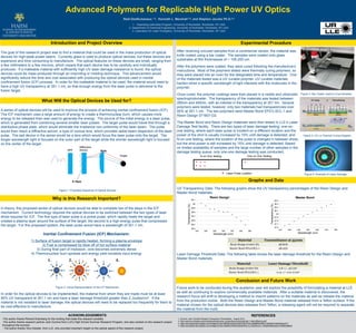
UV Transparency Data: The following graphs show the UV transparency percentages of the Resin Design and
Master Bond materials.
Laser Damage Threshold Data: The following table shows the laser damage threshold for the Resin Design and
Master Bond materials.
Graphs and Data
Figure 1: Proposed Sequence of Optical Devices
Figure 2: Visual Representation of the ICF Mechanism
Figure 3: Bar Coater Used to Coat Samples
Figure 4: UV vs Thermal Curing Diagram
Laser Pulse Location
One on One testing N on One testing:
N on One Testing One on One Testing
Figure 5: Example of Laser Damage
98.4
98.5
98.6
98.7
98.8
98.9
99
99.1
344 346 348 350 352 354 356
Transparency(%)
Wavelength (nm)
Resin Design
97.6
97.7
97.8
97.9
98
98.1
98.2
98.3
98.4
344 346 348 350 352 354 356
Transparency(%)
Wavelength (nm)
Master Bond
Material Transmittance at 351nm
Resin Design 071607-D2 98.80%
Master Bond EP21LSCL-1 98.05%
Material Laser Damage Threshold
Resin Design 071607-D2 2.8 +/- .5J/cm2
Master Bond EP21LSCL-1 0.14 +/- 0.01 J/cm2