1. Mesa College Art Gallery: Wall Mounting Display Owner’s Manual - R. Powell
1
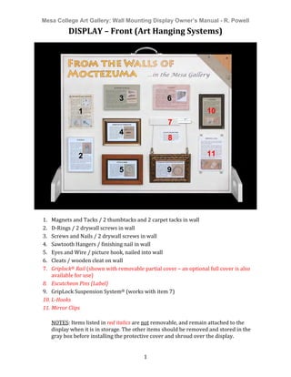
DISPLAY
–
Front
(Art
Hanging
Systems)
1. Magnets
and
Tacks
/
2
thumbtacks
and
2
carpet
tacks
in
wall
2. D-‐Rings
/
2
drywall
screws
in
wall
3. Screws
and
Nails
/
2
drywall
screws
in
wall
4. Sawtooth
Hangers
/
finishing
nail
in
wall
5. Eyes
and
Wire
/
picture
hook,
nailed
into
wall
6. Cleats
/
wooden
cleat
on
wall
7. Griplock®
Rail
(shown
with
removable
partial
cover
–
an
optional
full
cover
is
also
available
for
use)
8. Escutcheon
Pins
(Label)
9. GripLock
Suspension
System®
(works
with
item
7)
10. L-Hooks
11. Mirror
Clips
NOTES:
Items
listed
in
red
italics
are
not
removable,
and
remain
attached
to
the
display
when
it
is
in
storage.
The
other
items
should
be
removed
and
stored
in
the
gray
box
before
installing
the
protective
cover
and
shroud
over
the
display.
1
2
3
4
3
5
3
6
3
7
9
10
11
8
2. Mesa College Art Gallery: Wall Mounting Display Owner’s Manual - R. Powell
2
DISPLAY
–
Rear
(Wall
Construction
&
Hardware
Info)
1. Wall
Construction
–
Removable
descriptive
plaque
explaining
basic
wall
construction,
types,
and
materials.
2. Wall
Cross-‐section
–
Removable*,
compressed,
cut-‐away
view
of
a
wall
from
the
top,
with
gallery
wall
sheathing
on
left
and
drywall
only
on
right.
Right
side
also
shows
embedded
drywall
anchors.
3. Drywall
Anchors
–
Removable*
plaque
showing
drywall
anchors
and
descriptions.
Wires
connect
the
anchors
to
their
counterparts
in
the
Wall
Cross-‐section.
4. Common
Threaded
Fasteners
–
Removable
plaque
with
common
threaded
fasteners
and
brief
descriptions,
grouped
by
major
types
and
features.
NOTES:
*Wires
will
need
to
be
removed
to
detach
these
two
elements.
Wall
cross-‐
section
has
a
sliding
flush-‐mount
bracket
underneath
the
wooden
2x4,
but
a
screw
under
the
metal
2x4.
All
other
elements
are
connected
only
by
flush-‐mounts
–
slide
upward
and
lift
to
remove.
2 3
4
1
3. Mesa College Art Gallery: Wall Mounting Display Owner’s Manual - R. Powell
3
Supplemental
Box
Contents
(Removable
Display
Items)
1. Owner’s
Manaual
(this
document)
2. Small
tub
containing
4
magnets
and
1
optional
hole
plug
for
use
on
GripLock®
rail
3. “Magnets
and
Tacks”
display
item
4. “D-‐Rings”
display
item
5. “Screws
and
Nails”
display
item
6. “Sawtooth
Hangers”
display
item
7. “Eyes
and
Wire”
display
item
8. Bubblewrap-‐lined
box
for
storage
of
these
items
(includes
spare
red
vinyl
lines)
9. “Cleats”
display
item
10. Full
length
face
cover
for
GripLock®
Rail
11. Partial
face
cover
for
GripLock®
Rail
(shortened
length
and
bevel
cut
allow
details
of
rail
to
be
seen
without
needing
to
remove
cover)
12. “GripLock®”
display
item
13. Wooden
shim
for
dis/mounting
base
supports.
To
use,
lift
one
end
of
display,
and
slide
shim
under
it.
Taking
weight
off
of
an
end
makes
alignment
and
seating
of
base
supports,
and
securing
them
to
the
display
with
the
screw
knob
much
easier.
1
2
4
3
7
6
5
8
12
10
9
13
11
4. Mesa College Art Gallery: Wall Mounting Display Owner’s Manual - R. Powell
4
Storage
&
Assembly
Display
packed
for
storage
Removable
items
are
packed
separately
in
the
gray
box
as
previously
shown.
This
cardboard
“box”
is
a
shroud
–
it
has
no
bottom.
Do
not
try
to
lift
or
carry
the
display
by
holding
onto
the
cardboard!
An
opening
in
the
shroud
top
allows
the
display
to
be
carried
like
a
suitcase
using
the
top
handle.
Remove
the
shroud
by
sliding
it
straight
up.
Align
the
offset
opening
on
top
with
handle
when
replacing
the
shroud.
Front
side
of
display
with
foamboard
protector
in
place
Underneath
the
shroud,
a
foamboard
protector
covers
the
front
of
the
display.
Also
note
the
two
base
supports
that
are
attached
vertically
to
the
sides
of
the
display.
The
foamboard
protector
has
recesses
cut
into
it
to
provide
clearance
and
protection
for
the
non-‐
removable
items
on
the
display
front
during
storage.
It
also
has
a
perpendicular
cardboard
panel
with
an
opening
for
the
handle
along
its
top
(where
the
blue
tape
can
be
seen).
To
remove
the
protector,
pull
it
away
from
the
front
of
the
display
so
it
clears
the
non-‐
removable
items,
and
then
lift
it
straight
up
over
the
handle.
To
install
it,
do
the
reverse,
making
sure
that
all
of
the
recesses
are
aligned
with
the
non-‐
removable
items,
and
that
the
protector
is
centered
on
the
front
of
the
display
and
flat
against
its
top.
The
side
edges
should
align
with
the
edges
of
the
attached
base
supports.
The
black
knobs
extend
beyond
those
edges.
5. Mesa College Art Gallery: Wall Mounting Display Owner’s Manual - R. Powell
5
Display
in
storage
configuration
with
foamboard
protector
removed
This
is
the
same
view
of
the
display
with
the
foamboard
protector
removed.
The
“missing”
items
can
be
found
in
the
gray
box.
While
the
display
itself
is
relatively
stable,
it
does
weigh
50
lbs
and
could
fall
over
if
it
is
accidentally
bumped.
The
base
supports
should
be
removed
from
their
storage
configuration
(as
shown
here)
and
be
reattached
to
the
bottom
in
the
Display
Configuration
before
installing
the
removable
items
or
using
the
display.
Lift
&
Carry
Configuration
(Optional)
Here,
the
base
supports
are
shown
in
the
optional
Lift
&
Carry
Configuration.
To
reconfigure
the
supports,
completely
unscrew
the
black
knobs
and
pull
the
supports
away
from
the
display.
There
are
two
pegs
on
the
inside
face
of
each
support.
The
pegs
align
the
supports
with
holes
in
the
display
in
2
locations
and
3
different
configurations
for
various
purposes.
For
this
use,
remove
and
rotate
the
supports
90°
as
shown,
inserting
the
pegs
into
the
appropriate
holes
to
achieve
the
perpendicular
angle.
Firmly
seat
the
supports
flush
against
the
side
of
the
display,
and
then
screw
in
the
black
knobs
until
they
are
tight
and
the
supports
cannot
be
moved.
In
this
configuration,
the
supports
are
above
the
display’s
center
of
gravity
and
can
be
easily
grasped.
Since
the
display
weighs
50
lbs,
the
supports
allow
it
to
be
easily
lifted
by
two
people
onto
a
table
or
other
raised
surface.
This
is
also
a
convenient
way
for
two
people
to
move
the
display
over
short
distances.
6. Mesa College Art Gallery: Wall Mounting Display Owner’s Manual - R. Powell
6
A
single
individual
with
adequate
strength
can
also
lift
or
carry
the
display
using
only
the
“suitcase”
handle
on
top,
but
the
Lift
&
Carry
Configuration
requires
much
less
effort.
Display
Configuration
In
this
view,
the
display
is
shown
configured
for
use.
The
base
supports
are
now
securely
attached
to
the
display
sides
in
the
lower
screw
and
peg
holes,
as
previously
described.
By
temporarily
placing
the
wooden
shim
from
the
gray
box
under
the
display
(not
the
base
support)
near
one
end,
the
weight
is
removed
from
that
end.
Thus
using
the
shim
will
make
aligning
and
seating
the
supports,
as
well
as
screwing
in
the
black
knobs,
much
easier.
The
shim
should
also
be
used
when
removing
the
supports
from
the
Display
Configuration.
Ready
for
use
–
Front
Side
View
This
image
shows
all
of
the
removable
display
items
from
the
gray
box
mounted
in
their
appropriate
places
on
the
front
of
the
display.
Those
display
items
can
be
easily
removed
by
students
to
inspect
the
components
or
used
by
the
instructor
to
illustrate
an
overview
of
the
art
hanging
techniques
and
associated
hardware
used
in
the
Mesa
College
Art
Gallery.
7. Mesa College Art Gallery: Wall Mounting Display Owner’s Manual - R. Powell
7
Ready
for
use
–
Back
Side
View
The
reverse
side
of
the
display,
features
“interior”
views
of,
and
information
on
wall
construction,
common
drywall
anchors
(shown
both
embedded
and
with
application
information),
and
samples
of
common
threaded
fasteners
with
descriptions.
This
side
has
an
acrylic
cover
and
requires
no
preparation.
Specifications
and
Additional
Notes
Dimensions:
Display
structure
-‐
30”
H
x
34”
W
x
6”
D
(incl.
hardware
protrusions)
With
base
supports
deployed
for
display,
the
footprint
is
36”
W
x
20”
D
Configured
for
storage
in
cover
and
shroud
-‐
30”
H
x
37”
W
x
6½”
D
Weight:
Display,
not
including
removable
items
–
50
lbs
The
back
side
of
the
display,
shown
here
with
the
display
items
removed,
has
flush-‐
mount
cleats
and
brackets
to
secure
them
to
the
plywood.
After
removing
the
acrylic
cover,
most
of
the
items
can
be
slid
upward
and
pulled
out.
A
screwdriver
is
needed
only
for
the
cover
and
a
single
screw
securing
the
bottom
of
the
wall
cross-‐section
display.
Note
that
the
plywood
panel
is
actually
only
3/8”
thick
(see
following
item).
8. Mesa College Art Gallery: Wall Mounting Display Owner’s Manual - R. Powell
8
The
apparently
3/4”
thick
plywood
panel
is
only
3/8”
thick.
To
reduce
weight,
one
full
3/8”
panel
and
one
3/8”
by
2”
wide
edge
façade
were
laminated
together.
The
3/8”
façade,
behind
the
drywall
on
the
front
of
the
display,
has
two
large
voids
that
are
filled
with
sheets
of
foamboard
and
cardboard.
Thus
any
hardware
passing
through
the
drywall
(front
of
the
display)
will
only
engage
plywood
between
the
depths
of
7/8”
and
11/4".
The
hardware
samples
are
secured
to
the
platforms
using
epoxy
and
small
stand-‐off
cradles
I
designed
in
SketchUp
and
printed
on
a
3D
printer.
Randy
Powell
Feb.
2015
–
powell_randy@sbcglobal.net
ADDITIONAL
CREDITS:
Professor
Alessandra
Moctezuma
–
Notes,
reference
material,
tour
of
gallery
mounting
systems,
and
requirements
for
the
project.
Pat
Vine
–
Samples
of,
and
information
on,
mounting
hardware
used
in
the
gallery.
Also
provided
general
information
regarding
Mesa
Art
Gallery
practices.
Vijay
Hingorani
–
Assisted
in
optimizing
3D
model
of
hardware
stand-‐off
cradle
for
3D
printing
and
printed
out
initial
prototype
on
his
3D
printer.
SD
Public
Library
Fab
Lab
–
Printed
second
prototype
and
production
run
of
stand-‐off
cradles.
Also
provided
use
of
vinyl
cutter
for
graphics
on
front
side
of
display.
Home
Depot
(Lauren
at
Pt.
Loma
store)
–
Donated
the
metal
stud
used
in
the
display.