How to Assemble a Sink Base Vanity
•
0 likes•153 views

How to Assemble a Sink Base Vanity

Recommended
Recommended
More Related Content
What's hot
Viewers also liked
Viewers also liked (11)
Similar to How to Assemble a Sink Base Vanity
Similar to How to Assemble a Sink Base Vanity (20)
Recently uploaded
Recently uploaded (20)
How to Assemble a Sink Base Vanity
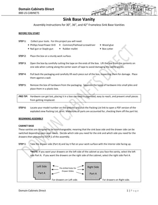
- 1. Domain Cabinets Direct 888-US-CABINETS Domain Cabinets Direct 1 | P a g e Sink Base Vanity Assembly Instructions for 30”, 36”, and 42” Frameless Sink Base Vanities BEFORE YOU START STEP 1: Collect your tools. For this project you will need: • Phillips head Power Drill • Nail gun or Staple gun • Common/Flathead screwdriver • Rubber mallet • Wood glue • Box cutter STEP 2: Place the box on a sturdy work surface. STEP 3: Open the box by carefully cutting the tape on the ends of the box. Lift the box from the contents on one side when cutting along the center seam of tape to avoid damaging the vanity pieces. STEP 4: Pull back the packaging and carefully lift each piece out of the box, inspecting them for damage. Place them against a wall. STEP 5: Remove the box of hardware from the packaging. Separate the types of hardware into small piles and place them in a plastic box. PRO TIP: Hardware can get lost, placing it in a box can keep it organized, easy to reach, and prevent small pieces from getting misplaced. STEP 6: Locate your model number on the website and click the Packing List link to open a PDF version of the exploded view Packing List, print. Make sure all parts are accounted for, checking them off the part list. BEGINNING ASSEMBLY CABINET BASE These vanities are designed to be interchangeable; meaning that the sink base side and the drawer side can be switched depending upon your needs. Decide which side you need for the sink and which side you need for the drawers then proceed to STEP 1 of the assembly. STEP 1: Take the drawer side (Part A) and lay it flat on your work surface with the interior side facing up. *NOTE: If you want your drawers on the left side of the cabinet as you face the vanity, select the left side Part A. If you want the drawers on the right side of the cabinet, select the right side Part A. For drawers on Left side. For drawers on Right side. Left Side Part A Right Side Part A Pre-drilled holes for Drawer Glides
- 2. Domain Cabinets Direct 888-US-CABINETS Domain Cabinets Direct 2 | P a g e STEP 2: Locate the Drawer Slides and remove them from any packaging. Fully extend each slide. The furthest segment of each slide is the Drawer Box Segment. Pressing the black plastic pin of the Drawer Box Segment upward, pull it from the remaining segments of the Drawer Slide and place it aside for later. STEP 3: Place the flat side of the remaining Drawer Slide on Part A, aligning it with the pre- drilled holes ensuring that the slide extends to the front of the cabinet. To get access to the drill holes, you will need to slide the inner track until the holes are visible. Using the 12mm Slide Screws, gently screw the drawer slides to Part A. Repeat as needed. NOTE: For a 2 drawer vanity, you will only install two Drawer Slides on this section of Part A. For a 3 drawer, you will install three Drawer Slides. Save the remaining slides for Part C. STEP 4: Locate Part B (Bottom Panel). As an interchangeable model, find the side of Part B that correlates with your drawer base. For example, a vanity with the drawers on the left (as you face it) will have pre-drilled screw holes on the middle left section in order to meet Part C (Center Divider). STEP 5: With the Drawer Slides attached to Part A, attach Part A to Part B (Bottom Panel) fitting wood dowels into the dowel holes. Secure Part A to Part B using four 50mm screws and ensure that the grove at the back of Part A meets the groove on Part B. NOTE: The grooves must align as they serve as the track to slide in the back panel later in the assembly process. STEP 6: Once Part A is attached to Part B, attach the other side of Part A to the bottom and lay the unit on its back. STEP 7: Locate Part J (Toe Kick) and fit it between the two Part As, aligning the pre-drilled screw holes. Using four 50mm screws, secure the toe kick to Part A (Left) and Part A (Right). STEP 8: Set the unit aside. STEP 9: Locate Part C (Center Divider) and place it flat on your work surface. Note that the finished edge of Part C indicates the front of the cabinet. If you chose a left side drawer orientation, attach the remaining Drawer Slides to Pre-drilled Drawer Slide holes on the left side of Part C. If you chose a right side drawer orientation, attach slides to the right side of Part C as described in STEP 3. PRO TIP: Many assemblers use wood glue to secure the dowels and create added strength. Excess wood glue can be removed with a damp towel. The dowels serve as an assembly aid but aren’t necessarily needed to construct this part of the cabinet. If you wish to forego the use of dowels for Part C only you may, the 50mm screws are more than sufficient to construct this part of the cabinet. Part B (Bottom Panel) Pre-drilled Screw Holes Pre-drilled Dowel Holes Back Panel Groove Part C (Center Divider) Part A (Side Panel) Part B (Bottom Panel) Left side drawer base orientation shown.
- 3. Domain Cabinets Direct 888-US-CABINETS Domain Cabinets Direct 3 | P a g e STEP 10: With the remaining Drawer Slides attached to Part C, place the wood dowels in the pre-drilled dowel holes located on the bottom of Part C. Placing the finished edge of Part C facing frontwards, secure Part C to Part B using wood dowels and two 50mm screws. STEP 11: Locate the two Part Ds (the Drawer Side Connecting Beams). Part D is a support bridge between the drawers. Using a small bead of wood glue, place wood dowels in the dowel holes on the side of each of the Part Ds. NOTE: When using wood glue to secure dowels for Part D, Part E, Part H, and Part G, remember to also add a bead of glue to their corresponding holes in Part A and Part B. Remember – what you do on one side, do on the other. STEP 12: With the finished edge facing the front of the unit, fit each Part D between Part A and Part C of the drawer side of the cabinet and secure 50mm. STEP 13: Locate Part E (Sink Side Connecting Beam). Using a small bead of wood glue, place the wood dowels in the dowel holes located at the ends of both sides of Part E. STEP 14: On the sink side, fit Part E between Part C and Part A (you may need a gentle tap of the mallet to fit it snugly) and secure using two 50mm screws just as you did with Part D on the drawer side. STEP 15: Locate Part H and place it on the top of the unit with the finished edge facing the front of the cabinet. Note that the pre-drilled holes on the top of Part H will match with the top of Part C on the drawer side. STEP 16: Using six 50mm screws, secure Part H to Part A (drawer side), Part C (drawer side), and Part A (sink side). PRO TIP: Securing Part H can be a little awkward by yourself. If you’re assembling the cabinet alone, secure Part H to Part C (the middle screws) first and then secure it on the sides at Part A (both sides). STEP 17: Locate Part F (Back Panel). IF YOU CHOOSE NOT TO INSTALL PART F, PROCEED TO STEP 19. NOTE: Many RTA assemblers/installers choose not to use the back panel due to the need to cut the panel to fit plumbing or plumbing inconsistencies. Omitting the back panel doesn’t compromise the strength of your cabinet. If you do choose to install the back panel, be sure to measure and cut a generous hole to accommodate your pipes for the sink base side. STEP 18: To install the back panel, face the finished side of Part F towards the front of the cabinet and carefully slide it along the groves at the rear of the unit. Be sure that the panel sits securely in the groves along the base as well as the sides. Part D Part E Part H Part A Part G Part F (Back Panel)
- 4. Domain Cabinets Direct 888-US-CABINETS Domain Cabinets Direct 4 | P a g e STEP 19: Locate Part G (Top Back Connecting Beam) and place it at the top of the unit over the back section just as you did with Part H in STEP 15 matching the pre-drilled holes in the midsection of Part G with those at the top of Part C. NOTE: IF YOU INSTALLED THE BACK PANEL, make sure to fit the groves of Part G over the top edge of the back panel. STEP 20: Using six 50mm screws, secure Part G to Part A (drawer side), Part C (drawer side), and Part A (sink side) as in STEP 16 for Part H. STEP 21: Locate the two Part Is (Back Reinforcement Beam). These support beams secure the cabinet to the wall and (if you install the back panel) secures the back panel in place. Fit one Part I along the back of the cabinet at the top with the angled pre-drilled hole in the center pointed upwards and secure it using one of the 30mm screws. Use 50mm screws to attach Part I at the sides. STEP 22: Repeat STEP 21 for the second Part I, securing it at the lower back section of the unit and ensuring the angled pre-drilled hole points downward. STEP 23: Locate the Sink Side False Panel (not shown in the exploded view). This panel allows you to connect the false drawer front to the sink side of the cabinet, above the sink base doors. Although there are no pre- drilled holes for this section, it can be easily installed using a staple gun or nail gun. Slide the sink side false panel into the hole between Part H and Part E so that it is framed, flush against the front edges of Parts A, C, E, and H and attach. This completes the cabinet base assembly. For door and drawer assembly & instructions, set the cabinet base aside and please continue. Part I (Back Reinforcement Beams) Sink Side False Panel
- 5. Domain Cabinets Direct 888-US-CABINETS Domain Cabinets Direct 5 | P a g e DOOR ATTACHMENT STEP 1: Locate the cabinet door(s) and door hinges and place them on a sturdy work surface. STEP 2: With the door facing down, insert the body of the hinge into the pre-cored holes on the door and secure using the screws included in the hinge kit. NOTE: Although the doors come pre-cored you should use a pocket level to align the hinges and make sure they are straight. STEP 3: Attach the door to the cabinet base on the sink side using the screws included in the hinge kit and aligning the hinges with the pre-drilled holes located on Part C and Part A. STEP 4: After setting the cabinet doors, they can be aligned (top to bottom, left to right) using the hinge position screws. The rear hinge position screw aligns top to bottom, the front position screw aligns the door from side to side. This concludes the door attachment instructions, for information on drawer assembly please continue. DRAWER ASSEMBLY Drawer assembly is simple yet precise. As all of the drawers use dovetail joining, it is important to be very careful during assembly and not to use unnecessary force as it could cause damage to the joiners. Each drawer consists of 2 Drawer Sides (Part K), 2 Drawer Aprons (Part L – for soft closing drawers the rear and back drawer aprons will vary slightly – the rear apron will have a notch at the base of each side whereas the front apron has a straight base and will contain two pre-drilled holes in order to attach the Door Face), 1 Drawer Bottom (Part M), and the Drawer Front (not shown in the exploded view of the part list). STEP 1: Collect your tools. For this project you will need: • Power Drill with Phillips screwdriver tip • Wood glue • Rubber mallet • 2 x 4 piece of scrap wood STEP 2: For each drawer, locate 2 Drawer Sides (Part K), 2 Drawer Aprons (Part L – one notched as well as one straight bottom with pre-drilled holes), 1 Drawer Bottom (Part M), and the Drawer Front and set them on a secure work surface bottom groove side facing upward. STEP 3: Set aside one of the drawer aprons (Part L) and one of the drawer sides (Part K). Place a small bead of wood glue between the dovetail joiners on one side of the front drawer apron (Part L). Cabinet Door Hinges Part L (Drawer Apron) Part K (Drawer Side)
- 6. Domain Cabinets Direct 888-US-CABINETS Domain Cabinets Direct 6 | P a g e Part L (Drawer Apron) Drawer Front STEP 4: Align the drawer side (Part K) with the glued side of the front drawer apron (Part L), ensuring the groves at the base of each piece align, and that the dovetail joiners align. Tap gently with the rubber mallet. PRO TIP: To fit the pieces together and avoid damage to the box and joiners, use the scrap 2 x 4 by placing it over the dovetail joint. Tap the mallet firmly but carefully. The 2 x 4 distributes the pressure of the mallet evenly and also keeps the mallet from leaving impressions in the wood. Remember – Although dovetail makes a very secure joining the dovetail tongues are vulnerable to damage until the sides are assembled, be careful and try not to force pieces together. STEP 5: Locate Part M (Drawer Bottom). Slide the drawer bottom into place along the grooves. STEP 6: Place a small bead of wood glue between the dovetail joiners on opposite side of the front drawer apron (Part L) already joined to the drawer side (Part K). Take the other drawer side (Part K) and slide it into place, aligning it with the glued dovetail joiners and the drawer base. Tap gently with the rubber mallet as described in STEP 4 and as listed in the above PRO TIP. STEP 7: Locate Part K (the back Drawer Side). Apply small beads of wood glue on both dovetail joiner sides. Align the back drawer apron (Part K) to the drawer sides (Part L) and drawer base, gently tapping it into place with the mallet. Repeat the instructions listed in the above PRO TIP. Repeat for all drawers STEP 2 – STEP 7 for all drawers. STEP 8: Locate the Drawer Box Segment of the drawer glides set aside earlier during the cabinet base assembly. STEP 9: Placing the assembled drawer box on its side, positioning the drawer box segment of the drawer glides so that the break end faces the front of the box and the pinched end faces the rear. Be sure to align the pre-drilled holes on the drawer sides with holes on the drawer slide. Secure using the 12mm slide screws. Repeat for each side of each drawer. STEP 10: Attaching Drawer Fronts: Use a piece of scribe molding as a spacer to align the fronts then attach from the back, inside the drawer, using 30mm screws. Clamps come in handy to hold the pieces in place during drilling. Repeat for each drawer and for the sink side false panel. Keep in mind you won’t necessarily attach the drawer fronts to the drawer aprons at the pre-drilled holes. Each style is different. As a rule, ALWAYS attach aprons to the “meat” of the drawer front to avoid drawer front damage. NOTE: When attaching handles, be sure not to over-tighten screws as it could damage the front. You may wish to attach hardware to the “meat” of the drawer front (such as the frame on a shaker-style cabinet). Part K (Drawer Side) Part L (Drawer Apron) Drawer Glide (End) Part L (Front Drawer Apron)
- 7. Domain Cabinets Direct 888-US-CABINETS Domain Cabinets Direct 7 | P a g e FINISHING UP Congratulations, you have just assembled your sink base vanity! To finish up, place the adhesive plastic stoppers at the corners of the drawers and doors to keep them from banging upon closing. Before assembling, take a moment to re-inspect your work a final time, looking for any screws that could be tightened or hinges that could be adjusted slightly.