SlideShare a Scribd company logo
1 of 10
Download to read offline
Trajectory Generation for FLS Functionality Validation
Priyasloka Arya, Tarali Bora & Madhava Gadicherla
Abstract
Safe landings contribute largely towards every successful aircraft flight. Electronic
instrumentation systems provide lateral and vertical guidance relative to the center of the
runway for landing. Electronic instrumentation systems which aid in landing are generally
Landing System Receivers. So, a landing system receiver’s capability should be validated for
different approaches and landing paths. In this paper we will discuss mainly how to generate
different simulated flight paths to check the lateral and vertical guidance functionalities provided
by the navigation receivers for FLS (Flight Management System (FMS) Based Landing System)
mode.
Introduction
There are various phases of flight of an aircraft, namely Preflight, Takeoff, Departure,
En-route, Descent, Approach and Landing. Approach and Landing are the most critical phases of
flight. Various landing systems are in use currently e.g. ILS (Instrument Landing System), GLS
(GNSS (global navigation satellite systems) based Landing System), MLS (Microwave Landing
System), VOR/DME (VHF Omni directional Range/Distance Measuring Equipment), VOR,
NDB(Non directional Beacon), and RNAV(Area Navigation).These landing systems can be
broadly classified depending on the type of guidance they provide. The possible approaches
available are precision approaches, which provide both lateral and vertical guidance (e.g. ILS,
MLS and GLS) and non-precision approaches, which provide only lateral guidance (e.g. GPS,
VOR/DME, VOR, NDB and RNAV).
Figure (1): Various Phases of Flight
A non precision approach has guidance only in horizontal direction whereas as precision
approach has guidance in both horizontal and vertical direction.
FLS Approach
Different landing systems use different methods to compute the vertical and lateral
guidance. Conventional landing systems like ILS and MLS depend on RF signals from the
ground, GLS uses GPS/GLONASS signals and pseudo range corrections from ground-based
systems, Optical landing systems use Fresnel lenses and Image-based landing systems
incorporate image sensors to generate the image of the runway and then correlate predicted
coordinates and the detected edge of the runway image to compute the guidance.
A new approach to landing – FLS - is proposed by Airbus to augment the landing system
capabilities. FLS is considered as a non-precision approach because it derives deviation
information from non-precision sources like INS, GPS, DME and ADF. But, FLS still provides
lateral and vertical deviation similar to a precision approach landing system.
While the other landing systems use some “physical” form of a representation of the
runway centerline (RF- or optical-based), FLS and GLS use a “synthetic” representation of the
same. They calculate lateral and vertical guidance using mathematical models and proprietary
algorithms. The accuracy of the computed guidance depends on the computational efficiency
and effectiveness of the algorithm.
In this paper we will talk about how to generate a descent path and landing scenario to
verify the FLS landing system capabilities and the FLS algorithm functionalities.
Glossary of FLS terms
• The Anchor Point is a reference point defined on the Approach path. FMS
calculates/defines this point for a particular runway.
• The Runway Threshold is defined as the touch down point of the a/c on the runway.
• The Runway Threshold Altitude is defined by the following formula:
Runway Threshold Altitude = AP Altitude –H0
Where, H0= a predefined height (usually 50 ft.)
• Local Vertical for the approach path is defined as a plane normal to the WGS-84 ellipsoid
at the Runway Threshold (RT).
• The Local Ground Plane for the approach is defined as a plane perpendicular to the local
vertical and passing through the Runway Threshold.
• The Vertical Plane is defined as a plane containing the projected point of AP on ground
and the AP and the line which is in direction of the FLS Beam Course.
• The final Approach Path is defined as a line in the vertical plane passing through the AP
with an inclination (defined by the Slope) relative to the local ground plane.
• The Approach Angle (AA) is defined as the absolute value of the Slope or inclination.
• The FLS Beam Course is obtained by the following formula:
FLS Beam Course =Local Magnetic Variation + Magnetic Course of the Runway
Figure (2): A Typical Descent Path
Figure (3): Virtual Beam Formation
RT
AP
A/C
AP1
H
PAP
β G
AA
α
O
The aircraft (a/c) tries to maintain its descent along the approach path (RT-AP line). This
approach line makes an angle (equal to approach angle) with local ground plane. The A/C-RT
line makes a deviation angle β with the RT-AP line. H is the projection of the a/c position on the
ground level plane at RT, along a line parallel to the normal at RT. The line HO subtends an
angle α with the runway line.
A virtual FLS beam is defined as a line passing through the anchor point and making an
angle to the horizontal plane at RT equal to the angle of approach. In the FLS mode, the landing
receiver receives the anchor point ident, anchor point latitude, longitude and altitude, the latitude,
longitude and altitude of the runway threshold, the slope of the FLS beam, the local magnetic
variation, and the magnetic course of the FLS beam, latitude, longitude and altitude of the
aircraft from the FMS system via Arinc-429 port. Thereafter the landing receiver calculates
lateral DDM (Difference in Depth of Modulation) and vertical DDM using this set of inputs. The
lateral and vertical DDMs are directly proportional to lateral deviation angle α and vertical
deviation angle β (see figure (2) above).
Flight Configuration of MMR
INPUTS OUTPUTS
Figure (4): An On Flight MMR configuration
The MMR O/Ps the lateral and vertical DDM on the ILS look-alike Arinc-429 buses,
where one is connected to the EFIS (Electronic Flight Instrument System) and other is connected
to the FMS (Autopilot).
* Anchor point indent
* Anchor point lat, long and alt
* Lat and long of runway threshold
* Slope of the FLS beam
* Local magnetic variation
* Magnetic course of the FLS beam
* Aircraft Lat, long and alt
* Aircraft Lat, long (fine)
MMR
* Lateral and Vertical dev
* Distance to Anchor Point
*Aircraft Lat, long and alt
* Distance to Anchor Point
L DDM
EFIS
INS
GNSS(GPS)
FMS
Autopilot
VOR
DME
V DDM
Simulation of Landing Phase In a Test Bench:
For the validation of the FLS function, we need to use multiple sets of input parameters
like aircraft latitude, longitude and altitude. The remaining parameters, which are specific to the
airport and runway, are considered to be constant. To simulate the landing phase, we need to
provide latitude, longitude and altitude for different positions along the descent path. Depending
on the aircraft position and runway selection, the MMR outputs DDM and the status of the DDM
(i.e. SSM (Sign/Status Matrix) is set to NO (Normal operation) or NCD (No computed Data)). If
the distance between the aircraft position and anchor point is within some predefined limit, DDM
status show NO, otherwise it indicates NCD.
A typical Test Bench set up
INPUTS OUTPUTS
Test Report
Figure (5): Test Bench configuration of MMR
TEST
BENCH
* Anchor point indent
* Anchor point lat, long and alt
* Lat and long of runway threshold
* Slope of the FLS beam
* Local magnetic variation
* Magnetic course of the FLS beam
MMR* Aircraft Lat, long and alt
* Lateral and Vertical Deviation
* Distance to Anchor Point
* Aircraft Lat, long and alt
* Distance to Anchor Point
* Aircraft Lat, long (fine)
Pass/Fail Criteria
There can be different methods to generate test points along the chosen descent path. One
such approach is where we consider a set of discrete points along the path.
An approach path can be chosen which is above/below and/or to the right/left of the ideal
approach path. The distance from the anchor point and the required lateral and vertical DDM are
inputs. From the lateral DDM the lateral deviation angle can be computed. Using standard
navigation algorithms e.g., Sodano or Vincenty direct equations the latitude and longitude can be
computed; and given the vertical DDM, the altitude of the a/c can be computed. Similarly other
points can be chosen along the path. These points can also be fed to the MMR during testing and
DDM outputs from the MMR can be compared to the expected theoretical DDMs as computed
above. The pros and cons of this kind of approach are given below.
Pros:
• We can generate different discrete points by a piece of software program.
Cons:
• The discrete points generated could be unrealistic considering aircraft dynamics, i.e., it
may be impossible for the aircraft to move from one test point to the next test point with
given speed and acceleration.
Another approach is to use a third party tool like Spirent SimGEN© which simulates the GPS
signals, corrections and aircraft dynamics like acceleration, turn, climb and speed. It has the
provision for defining different way points on the flight path. A trajectory can be generated by
connecting all the waypoints. A typical motion or aircraft command file looks like:
Figure (6): A Snapshot of an Aircraft Motion file
Figure (7): A Simulated Trajectory in SimGen
Pros:
• By providing the discrete waypoints, a trajectory can be generated connecting all the
given points.
Cons:
• It is a very good way for simulating all possible paths of all phases except landing phase
where we have to again calculate discrete points. The discrete points may be unrealistic
as proper dynamics of the aircraft during landing should be known before hand.
Proposed Way of Trajectory Generation
So a different methodology is proposed for a realistic path generation for landing phase.
Microsoft Flight Simulator© (FS) 2004 is chosen for flight model selection (Boeing/Airbus),
airport selection, flight parameter selection (engine command, autopilot command, radio
command, Instrument command, and view command).Using this Simulator an appropriate path
can be generated .The details of this scheme are given below.
(Flight Simulator)
(FSUIPC)
Test Report
Flight Parameter
Extraction Program
TEST
BENCH
(FLS ALGO
IMPLEMENTED)
MMR
Trajectory File
Visualization Tool
(With FLS Algo implemented)
Joystick
Approach
Volume
Pass/Fail Criteria
--- Dotted Line shows proposed plan
Figure (8): Schematics of Proposed Plan
Flight Simulator provides ample scope for generating a test flight path. It lets the user
choose an aircraft model from a pool of available models, the flight plan can be prepared
depending on the source and destination airport and different navigation schemes can be chosen
e.g., GPS and VOR. The aircraft can be controlled by a joystick and a flight path is generated.
A data extraction program is written to extract data (latitude, longitude, altitude, heading,
roll, pitch, yaw etc.) from Flight Simulator’s common memory and provide it to another
visualization tool in near-real time. This proposed tool is developed in VC++ IDE with OpenGL
API. Using this visualization tool, the user can visualize the aircraft and its path in three
dimensions with source, destination airports and the approach volume (see Figure (8)) for the
landing. Viewing the flight path in three dimensions using the visualization tool, the engineer can
fly the path in Microsoft Flight Simulator to generate a test path along waypoints that have been
predefined in the visualization tool, thus generating a more realistic flight path.
This novel approach is suggested for realistic flight path generation for testing of the FLS
function. The generated trajectory file consisting of aircraft latitude, longitude and altitude can
be provided as an input to the MMR. The DDMs computed by the MMR are then fed to the test
bench for comparison with theoretically generated values and generation of a pass/fail report
Here, it must be ensured that the FLS algorithm implemented in the Test Bench should be
the same as the algorithm implemented in MMR.
The salient features of the proposed methodology are furnished below.
• The aircraft dynamics are taken care of in Microsoft Flight Simulator (FS).
• FS has a huge database of airports and their facilities related to communication and
navigation at ATC (Air Traffic Control).
• FS has various a/c models. So, a particular aircraft type can be selected for flight.
• FS gives graphic instrument panel to control different instruments, various indicators
(e.g. Airspeed, Altimeter, Heading etc) for display and radios (e.g. VOR, DME, ILS etc)
for navigation.
• Flight trajectories can be generated by using joystick controls.
• The visualization tool helps as a manual feedback so that we can restrict the aircraft in the
approach volume.
• The actual position of the aircraft and its relative position to the destination airport can be
easily comprehended by using the visualization model.
In this proposed implementation there are some limitations which are to be addressed.
• Flying an aircraft in FS using the visual model needs a minimum required skill.
• The data update from the flight simulator is around 1 sec.
Conclusion and Scope:
These above issues are not serious constraints for the proposed implementation. With a
little dedicated effort, a good flight path can be generated in Flight Simulator. Also, solutions
could be worked out to increase the data update rate, but the1 sec update rate is deemed to be
sufficient for testing.
The deviation data (DDMs) can be compared with respect to other legacy landing system like
ILS for accuracy verification of FLS algorithm.
Acknowledgement:
The authors express their deep gratitude towards their colleagues Ashish, Naina
Anupama and Nagmani for proof reading the manuscript and giving their feedbacks. We are
grateful to Mr.George Koilpillai for his encouragement while carrying out this work. Special
thanks for Rajnikant for resolving proprietary issue and his support and motivation.
References:
1. Avionics Navigation Systems, Myron Kayton and Walter, A Wiley-International
Publication
2. Windows Sockets Network Programming by B. Quinn & D. Shute, Addison-Wesley
Publishing Company
3. Arinc-755-3(Multi Mode Receiver (Digital)
4. Redbook(The official guide to learn OpenGL) Version 1.1
5. VC++,COM and Beyond, Yeshvant P Kanetkar,Sudesh Saoji,BPB Publication
6. FSUIPC Documentation
7. United States-Patent Application Publication Pub. No.: US2004/0199304A1
AIRCRAFT PILOTING SYSTEM, AT LEAST FOL PILOTING THE AIRCRAFT
DURING A NON PRECISION APPROACH WITH A VIEW TO A LANDING
Inventors: Gilles Tatham, La Salvetat, Saint Gilles (FR), Eric Peyrucain, Saint
Genies, Bellevue

More Related Content

What's hot

Site surveying 1 - done
Site surveying 1 - done Site surveying 1 - done
Site surveying 1 - done w ss
 
Site surveying-almost-1
Site surveying-almost-1Site surveying-almost-1
Site surveying-almost-1Lam Yu
 
Airport runway By Nikhil Pakwanne
Airport runway By Nikhil PakwanneAirport runway By Nikhil Pakwanne
Airport runway By Nikhil PakwanneNIKHIL PAKWANNE
 
Site surveying-report-leveling
Site surveying-report-levelingSite surveying-report-leveling
Site surveying-report-levelingXinYee Khoo
 
Levelling report-1
Levelling report-1Levelling report-1
Levelling report-1tfkc1212
 
Site surveying report1
Site surveying report1Site surveying report1
Site surveying report1Est
 
Project 1- Levelling
Project 1- Levelling Project 1- Levelling
Project 1- Levelling seenyee
 
Field work 1 (1)
Field work 1 (1)Field work 1 (1)
Field work 1 (1)Chee Lee
 
Site Surveying Report 1 (Levelling)
Site Surveying Report 1 (Levelling)Site Surveying Report 1 (Levelling)
Site Surveying Report 1 (Levelling)Haziq1511
 
Airport drainage
Airport drainageAirport drainage
Airport drainagejagadish108
 
Assignment 1 - Levelling
Assignment 1 - LevellingAssignment 1 - Levelling
Assignment 1 - LevellingKai Yun Pang
 

What's hot (18)

Typical electronic
Typical electronicTypical electronic
Typical electronic
 
Airport marking
Airport markingAirport marking
Airport marking
 
Site surveying 1 - done
Site surveying 1 - done Site surveying 1 - done
Site surveying 1 - done
 
Site surveying-almost-1
Site surveying-almost-1Site surveying-almost-1
Site surveying-almost-1
 
Levelling
LevellingLevelling
Levelling
 
Airport runway By Nikhil Pakwanne
Airport runway By Nikhil PakwanneAirport runway By Nikhil Pakwanne
Airport runway By Nikhil Pakwanne
 
Site surveying-report-leveling
Site surveying-report-levelingSite surveying-report-leveling
Site surveying-report-leveling
 
Levelling report-1
Levelling report-1Levelling report-1
Levelling report-1
 
Autopilot Technology
Autopilot TechnologyAutopilot Technology
Autopilot Technology
 
Site surveying report1
Site surveying report1Site surveying report1
Site surveying report1
 
Project 1- Levelling
Project 1- Levelling Project 1- Levelling
Project 1- Levelling
 
Field work 1 (1)
Field work 1 (1)Field work 1 (1)
Field work 1 (1)
 
Airfield ground lighting (AGL)
Airfield ground lighting (AGL)Airfield ground lighting (AGL)
Airfield ground lighting (AGL)
 
Site Surveying Report 1 (Levelling)
Site Surveying Report 1 (Levelling)Site Surveying Report 1 (Levelling)
Site Surveying Report 1 (Levelling)
 
Airport drainage
Airport drainageAirport drainage
Airport drainage
 
Levelling
LevellingLevelling
Levelling
 
Assignment 1 - Levelling
Assignment 1 - LevellingAssignment 1 - Levelling
Assignment 1 - Levelling
 
Digitam
DigitamDigitam
Digitam
 

Similar to Trajectory Generation for FLS Functionality Validation

B737NG FMC
B737NG FMCB737NG FMC
B737NG FMCtheoryce
 
Quick reference guide ans
Quick reference guide  ansQuick reference guide  ans
Quick reference guide ansZameer Basha
 
AREA NAVIGATION (RNAV) System Description.docx
AREA NAVIGATION (RNAV) System Description.docxAREA NAVIGATION (RNAV) System Description.docx
AREA NAVIGATION (RNAV) System Description.docxCyprianObota
 
737 ng fmc guide toohey
737 ng fmc guide toohey737 ng fmc guide toohey
737 ng fmc guide tooheyJim Toohey
 
5.1 Electronic Instrument Systems
5.1 Electronic Instrument Systems5.1 Electronic Instrument Systems
5.1 Electronic Instrument Systemslpapadop
 
Instrument landing system.docx
Instrument landing system.docxInstrument landing system.docx
Instrument landing system.docxCyprianObota
 
Introduction to aircraft communicating system
Introduction to aircraft communicating systemIntroduction to aircraft communicating system
Introduction to aircraft communicating systemRosy Satwe
 
Radio and Radar: Radar Continued - systems
Radio and Radar: Radar Continued - systemsRadio and Radar: Radar Continued - systems
Radio and Radar: Radar Continued - systemsJess Peters
 
Media Object File Flt Ops Sop Seq02
Media Object File Flt Ops Sop Seq02Media Object File Flt Ops Sop Seq02
Media Object File Flt Ops Sop Seq02syed viquar
 
Visualizing the Flight Test Data and its Simulation
Visualizing the Flight Test Data and its SimulationVisualizing the Flight Test Data and its Simulation
Visualizing the Flight Test Data and its SimulationIRJET Journal
 
aircraft navigation equipment
aircraft navigation equipmentaircraft navigation equipment
aircraft navigation equipmentAbhishekLalkiya
 
Aircraft navigation system
Aircraft navigation systemAircraft navigation system
Aircraft navigation systemKrishikesh Singh
 

Similar to Trajectory Generation for FLS Functionality Validation (20)

B737NG FMC
B737NG FMCB737NG FMC
B737NG FMC
 
Quick reference guide ans
Quick reference guide  ansQuick reference guide  ans
Quick reference guide ans
 
AREA NAVIGATION (RNAV) System Description.docx
AREA NAVIGATION (RNAV) System Description.docxAREA NAVIGATION (RNAV) System Description.docx
AREA NAVIGATION (RNAV) System Description.docx
 
737 ng fmc guide toohey
737 ng fmc guide toohey737 ng fmc guide toohey
737 ng fmc guide toohey
 
5.1 Electronic Instrument Systems
5.1 Electronic Instrument Systems5.1 Electronic Instrument Systems
5.1 Electronic Instrument Systems
 
SGD 2016 - Systems explanation DEMO#1
SGD 2016 - Systems explanation DEMO#1SGD 2016 - Systems explanation DEMO#1
SGD 2016 - Systems explanation DEMO#1
 
Formation control
Formation controlFormation control
Formation control
 
Instrument landing system.docx
Instrument landing system.docxInstrument landing system.docx
Instrument landing system.docx
 
Introduction to aircraft communicating system
Introduction to aircraft communicating systemIntroduction to aircraft communicating system
Introduction to aircraft communicating system
 
Radio and Radar: Radar Continued - systems
Radio and Radar: Radar Continued - systemsRadio and Radar: Radar Continued - systems
Radio and Radar: Radar Continued - systems
 
Media Object File Flt Ops Sop Seq02
Media Object File Flt Ops Sop Seq02Media Object File Flt Ops Sop Seq02
Media Object File Flt Ops Sop Seq02
 
Avionics
AvionicsAvionics
Avionics
 
Flight landing Project
Flight landing ProjectFlight landing Project
Flight landing Project
 
Flight Instrument .
Flight Instrument .Flight Instrument .
Flight Instrument .
 
Visualizing the Flight Test Data and its Simulation
Visualizing the Flight Test Data and its SimulationVisualizing the Flight Test Data and its Simulation
Visualizing the Flight Test Data and its Simulation
 
F04 06 4451
F04 06 4451F04 06 4451
F04 06 4451
 
Gain scheduling automatic landing system by modeling Ground Effect
Gain scheduling automatic landing system by modeling Ground EffectGain scheduling automatic landing system by modeling Ground Effect
Gain scheduling automatic landing system by modeling Ground Effect
 
aircraft navigation equipment
aircraft navigation equipmentaircraft navigation equipment
aircraft navigation equipment
 
A320 auto flight
A320  auto flightA320  auto flight
A320 auto flight
 
Aircraft navigation system
Aircraft navigation systemAircraft navigation system
Aircraft navigation system
 

Recently uploaded

What are the features of Vehicle Tracking System?
What are the features of Vehicle Tracking System?What are the features of Vehicle Tracking System?
What are the features of Vehicle Tracking System?Watsoo Telematics
 
Cloud Management Software Platforms: OpenStack
Cloud Management Software Platforms: OpenStackCloud Management Software Platforms: OpenStack
Cloud Management Software Platforms: OpenStackVICTOR MAESTRE RAMIREZ
 
Russian Call Girls in Karol Bagh Aasnvi ➡️ 8264348440 💋📞 Independent Escort S...
Russian Call Girls in Karol Bagh Aasnvi ➡️ 8264348440 💋📞 Independent Escort S...Russian Call Girls in Karol Bagh Aasnvi ➡️ 8264348440 💋📞 Independent Escort S...
Russian Call Girls in Karol Bagh Aasnvi ➡️ 8264348440 💋📞 Independent Escort S...soniya singh
 
KnowAPIs-UnknownPerf-jaxMainz-2024 (1).pptx
KnowAPIs-UnknownPerf-jaxMainz-2024 (1).pptxKnowAPIs-UnknownPerf-jaxMainz-2024 (1).pptx
KnowAPIs-UnknownPerf-jaxMainz-2024 (1).pptxTier1 app
 
Professional Resume Template for Software Developers
Professional Resume Template for Software DevelopersProfessional Resume Template for Software Developers
Professional Resume Template for Software DevelopersVinodh Ram
 
The Essentials of Digital Experience Monitoring_ A Comprehensive Guide.pdf
The Essentials of Digital Experience Monitoring_ A Comprehensive Guide.pdfThe Essentials of Digital Experience Monitoring_ A Comprehensive Guide.pdf
The Essentials of Digital Experience Monitoring_ A Comprehensive Guide.pdfkalichargn70th171
 
Project Based Learning (A.I).pptx detail explanation
Project Based Learning (A.I).pptx detail explanationProject Based Learning (A.I).pptx detail explanation
Project Based Learning (A.I).pptx detail explanationkaushalgiri8080
 
XpertSolvers: Your Partner in Building Innovative Software Solutions
XpertSolvers: Your Partner in Building Innovative Software SolutionsXpertSolvers: Your Partner in Building Innovative Software Solutions
XpertSolvers: Your Partner in Building Innovative Software SolutionsMehedi Hasan Shohan
 
Salesforce Certified Field Service Consultant
Salesforce Certified Field Service ConsultantSalesforce Certified Field Service Consultant
Salesforce Certified Field Service ConsultantAxelRicardoTrocheRiq
 
buds n tech IT solutions
buds n  tech IT                solutionsbuds n  tech IT                solutions
buds n tech IT solutionsmonugehlot87
 
Short Story: Unveiling the Reasoning Abilities of Large Language Models by Ke...
Short Story: Unveiling the Reasoning Abilities of Large Language Models by Ke...Short Story: Unveiling the Reasoning Abilities of Large Language Models by Ke...
Short Story: Unveiling the Reasoning Abilities of Large Language Models by Ke...kellynguyen01
 
Building Real-Time Data Pipelines: Stream & Batch Processing workshop Slide
Building Real-Time Data Pipelines: Stream & Batch Processing workshop SlideBuilding Real-Time Data Pipelines: Stream & Batch Processing workshop Slide
Building Real-Time Data Pipelines: Stream & Batch Processing workshop SlideChristina Lin
 
EY_Graph Database Powered Sustainability
EY_Graph Database Powered SustainabilityEY_Graph Database Powered Sustainability
EY_Graph Database Powered SustainabilityNeo4j
 
why an Opensea Clone Script might be your perfect match.pdf
why an Opensea Clone Script might be your perfect match.pdfwhy an Opensea Clone Script might be your perfect match.pdf
why an Opensea Clone Script might be your perfect match.pdfjoe51371421
 
Advancing Engineering with AI through the Next Generation of Strategic Projec...
Advancing Engineering with AI through the Next Generation of Strategic Projec...Advancing Engineering with AI through the Next Generation of Strategic Projec...
Advancing Engineering with AI through the Next Generation of Strategic Projec...OnePlan Solutions
 
BATTLEFIELD ORM: TIPS, TACTICS AND STRATEGIES FOR CONQUERING YOUR DATABASE
BATTLEFIELD ORM: TIPS, TACTICS AND STRATEGIES FOR CONQUERING YOUR DATABASEBATTLEFIELD ORM: TIPS, TACTICS AND STRATEGIES FOR CONQUERING YOUR DATABASE
BATTLEFIELD ORM: TIPS, TACTICS AND STRATEGIES FOR CONQUERING YOUR DATABASEOrtus Solutions, Corp
 
Engage Usergroup 2024 - The Good The Bad_The Ugly
Engage Usergroup 2024 - The Good The Bad_The UglyEngage Usergroup 2024 - The Good The Bad_The Ugly
Engage Usergroup 2024 - The Good The Bad_The UglyFrank van der Linden
 
cybersecurity notes for mca students for learning
cybersecurity notes for mca students for learningcybersecurity notes for mca students for learning
cybersecurity notes for mca students for learningVitsRangannavar
 
Unit 1.1 Excite Part 1, class 9, cbse...
Unit 1.1 Excite Part 1, class 9, cbse...Unit 1.1 Excite Part 1, class 9, cbse...
Unit 1.1 Excite Part 1, class 9, cbse...aditisharan08
 

Recently uploaded (20)

What are the features of Vehicle Tracking System?
What are the features of Vehicle Tracking System?What are the features of Vehicle Tracking System?
What are the features of Vehicle Tracking System?
 
Cloud Management Software Platforms: OpenStack
Cloud Management Software Platforms: OpenStackCloud Management Software Platforms: OpenStack
Cloud Management Software Platforms: OpenStack
 
Russian Call Girls in Karol Bagh Aasnvi ➡️ 8264348440 💋📞 Independent Escort S...
Russian Call Girls in Karol Bagh Aasnvi ➡️ 8264348440 💋📞 Independent Escort S...Russian Call Girls in Karol Bagh Aasnvi ➡️ 8264348440 💋📞 Independent Escort S...
Russian Call Girls in Karol Bagh Aasnvi ➡️ 8264348440 💋📞 Independent Escort S...
 
KnowAPIs-UnknownPerf-jaxMainz-2024 (1).pptx
KnowAPIs-UnknownPerf-jaxMainz-2024 (1).pptxKnowAPIs-UnknownPerf-jaxMainz-2024 (1).pptx
KnowAPIs-UnknownPerf-jaxMainz-2024 (1).pptx
 
Professional Resume Template for Software Developers
Professional Resume Template for Software DevelopersProfessional Resume Template for Software Developers
Professional Resume Template for Software Developers
 
Call Girls In Mukherjee Nagar 📱 9999965857 🤩 Delhi 🫦 HOT AND SEXY VVIP 🍎 SE...
Call Girls In Mukherjee Nagar 📱  9999965857  🤩 Delhi 🫦 HOT AND SEXY VVIP 🍎 SE...Call Girls In Mukherjee Nagar 📱  9999965857  🤩 Delhi 🫦 HOT AND SEXY VVIP 🍎 SE...
Call Girls In Mukherjee Nagar 📱 9999965857 🤩 Delhi 🫦 HOT AND SEXY VVIP 🍎 SE...
 
The Essentials of Digital Experience Monitoring_ A Comprehensive Guide.pdf
The Essentials of Digital Experience Monitoring_ A Comprehensive Guide.pdfThe Essentials of Digital Experience Monitoring_ A Comprehensive Guide.pdf
The Essentials of Digital Experience Monitoring_ A Comprehensive Guide.pdf
 
Project Based Learning (A.I).pptx detail explanation
Project Based Learning (A.I).pptx detail explanationProject Based Learning (A.I).pptx detail explanation
Project Based Learning (A.I).pptx detail explanation
 
XpertSolvers: Your Partner in Building Innovative Software Solutions
XpertSolvers: Your Partner in Building Innovative Software SolutionsXpertSolvers: Your Partner in Building Innovative Software Solutions
XpertSolvers: Your Partner in Building Innovative Software Solutions
 
Salesforce Certified Field Service Consultant
Salesforce Certified Field Service ConsultantSalesforce Certified Field Service Consultant
Salesforce Certified Field Service Consultant
 
buds n tech IT solutions
buds n  tech IT                solutionsbuds n  tech IT                solutions
buds n tech IT solutions
 
Short Story: Unveiling the Reasoning Abilities of Large Language Models by Ke...
Short Story: Unveiling the Reasoning Abilities of Large Language Models by Ke...Short Story: Unveiling the Reasoning Abilities of Large Language Models by Ke...
Short Story: Unveiling the Reasoning Abilities of Large Language Models by Ke...
 
Building Real-Time Data Pipelines: Stream & Batch Processing workshop Slide
Building Real-Time Data Pipelines: Stream & Batch Processing workshop SlideBuilding Real-Time Data Pipelines: Stream & Batch Processing workshop Slide
Building Real-Time Data Pipelines: Stream & Batch Processing workshop Slide
 
EY_Graph Database Powered Sustainability
EY_Graph Database Powered SustainabilityEY_Graph Database Powered Sustainability
EY_Graph Database Powered Sustainability
 
why an Opensea Clone Script might be your perfect match.pdf
why an Opensea Clone Script might be your perfect match.pdfwhy an Opensea Clone Script might be your perfect match.pdf
why an Opensea Clone Script might be your perfect match.pdf
 
Advancing Engineering with AI through the Next Generation of Strategic Projec...
Advancing Engineering with AI through the Next Generation of Strategic Projec...Advancing Engineering with AI through the Next Generation of Strategic Projec...
Advancing Engineering with AI through the Next Generation of Strategic Projec...
 
BATTLEFIELD ORM: TIPS, TACTICS AND STRATEGIES FOR CONQUERING YOUR DATABASE
BATTLEFIELD ORM: TIPS, TACTICS AND STRATEGIES FOR CONQUERING YOUR DATABASEBATTLEFIELD ORM: TIPS, TACTICS AND STRATEGIES FOR CONQUERING YOUR DATABASE
BATTLEFIELD ORM: TIPS, TACTICS AND STRATEGIES FOR CONQUERING YOUR DATABASE
 
Engage Usergroup 2024 - The Good The Bad_The Ugly
Engage Usergroup 2024 - The Good The Bad_The UglyEngage Usergroup 2024 - The Good The Bad_The Ugly
Engage Usergroup 2024 - The Good The Bad_The Ugly
 
cybersecurity notes for mca students for learning
cybersecurity notes for mca students for learningcybersecurity notes for mca students for learning
cybersecurity notes for mca students for learning
 
Unit 1.1 Excite Part 1, class 9, cbse...
Unit 1.1 Excite Part 1, class 9, cbse...Unit 1.1 Excite Part 1, class 9, cbse...
Unit 1.1 Excite Part 1, class 9, cbse...
 

Trajectory Generation for FLS Functionality Validation

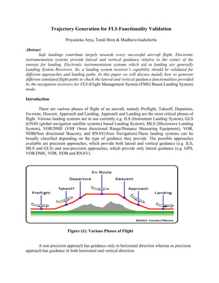
  • 1. Trajectory Generation for FLS Functionality Validation Priyasloka Arya, Tarali Bora & Madhava Gadicherla Abstract Safe landings contribute largely towards every successful aircraft flight. Electronic instrumentation systems provide lateral and vertical guidance relative to the center of the runway for landing. Electronic instrumentation systems which aid in landing are generally Landing System Receivers. So, a landing system receiver’s capability should be validated for different approaches and landing paths. In this paper we will discuss mainly how to generate different simulated flight paths to check the lateral and vertical guidance functionalities provided by the navigation receivers for FLS (Flight Management System (FMS) Based Landing System) mode. Introduction There are various phases of flight of an aircraft, namely Preflight, Takeoff, Departure, En-route, Descent, Approach and Landing. Approach and Landing are the most critical phases of flight. Various landing systems are in use currently e.g. ILS (Instrument Landing System), GLS (GNSS (global navigation satellite systems) based Landing System), MLS (Microwave Landing System), VOR/DME (VHF Omni directional Range/Distance Measuring Equipment), VOR, NDB(Non directional Beacon), and RNAV(Area Navigation).These landing systems can be broadly classified depending on the type of guidance they provide. The possible approaches available are precision approaches, which provide both lateral and vertical guidance (e.g. ILS, MLS and GLS) and non-precision approaches, which provide only lateral guidance (e.g. GPS, VOR/DME, VOR, NDB and RNAV). Figure (1): Various Phases of Flight A non precision approach has guidance only in horizontal direction whereas as precision approach has guidance in both horizontal and vertical direction.
  • 2. FLS Approach Different landing systems use different methods to compute the vertical and lateral guidance. Conventional landing systems like ILS and MLS depend on RF signals from the ground, GLS uses GPS/GLONASS signals and pseudo range corrections from ground-based systems, Optical landing systems use Fresnel lenses and Image-based landing systems incorporate image sensors to generate the image of the runway and then correlate predicted coordinates and the detected edge of the runway image to compute the guidance. A new approach to landing – FLS - is proposed by Airbus to augment the landing system capabilities. FLS is considered as a non-precision approach because it derives deviation information from non-precision sources like INS, GPS, DME and ADF. But, FLS still provides lateral and vertical deviation similar to a precision approach landing system. While the other landing systems use some “physical” form of a representation of the runway centerline (RF- or optical-based), FLS and GLS use a “synthetic” representation of the same. They calculate lateral and vertical guidance using mathematical models and proprietary algorithms. The accuracy of the computed guidance depends on the computational efficiency and effectiveness of the algorithm. In this paper we will talk about how to generate a descent path and landing scenario to verify the FLS landing system capabilities and the FLS algorithm functionalities. Glossary of FLS terms • The Anchor Point is a reference point defined on the Approach path. FMS calculates/defines this point for a particular runway. • The Runway Threshold is defined as the touch down point of the a/c on the runway. • The Runway Threshold Altitude is defined by the following formula: Runway Threshold Altitude = AP Altitude –H0 Where, H0= a predefined height (usually 50 ft.) • Local Vertical for the approach path is defined as a plane normal to the WGS-84 ellipsoid at the Runway Threshold (RT). • The Local Ground Plane for the approach is defined as a plane perpendicular to the local vertical and passing through the Runway Threshold. • The Vertical Plane is defined as a plane containing the projected point of AP on ground and the AP and the line which is in direction of the FLS Beam Course. • The final Approach Path is defined as a line in the vertical plane passing through the AP with an inclination (defined by the Slope) relative to the local ground plane. • The Approach Angle (AA) is defined as the absolute value of the Slope or inclination. • The FLS Beam Course is obtained by the following formula: FLS Beam Course =Local Magnetic Variation + Magnetic Course of the Runway
  • 3. Figure (2): A Typical Descent Path Figure (3): Virtual Beam Formation RT AP A/C AP1 H PAP β G AA α O
  • 4. The aircraft (a/c) tries to maintain its descent along the approach path (RT-AP line). This approach line makes an angle (equal to approach angle) with local ground plane. The A/C-RT line makes a deviation angle β with the RT-AP line. H is the projection of the a/c position on the ground level plane at RT, along a line parallel to the normal at RT. The line HO subtends an angle α with the runway line. A virtual FLS beam is defined as a line passing through the anchor point and making an angle to the horizontal plane at RT equal to the angle of approach. In the FLS mode, the landing receiver receives the anchor point ident, anchor point latitude, longitude and altitude, the latitude, longitude and altitude of the runway threshold, the slope of the FLS beam, the local magnetic variation, and the magnetic course of the FLS beam, latitude, longitude and altitude of the aircraft from the FMS system via Arinc-429 port. Thereafter the landing receiver calculates lateral DDM (Difference in Depth of Modulation) and vertical DDM using this set of inputs. The lateral and vertical DDMs are directly proportional to lateral deviation angle α and vertical deviation angle β (see figure (2) above). Flight Configuration of MMR INPUTS OUTPUTS Figure (4): An On Flight MMR configuration The MMR O/Ps the lateral and vertical DDM on the ILS look-alike Arinc-429 buses, where one is connected to the EFIS (Electronic Flight Instrument System) and other is connected to the FMS (Autopilot). * Anchor point indent * Anchor point lat, long and alt * Lat and long of runway threshold * Slope of the FLS beam * Local magnetic variation * Magnetic course of the FLS beam * Aircraft Lat, long and alt * Aircraft Lat, long (fine) MMR * Lateral and Vertical dev * Distance to Anchor Point *Aircraft Lat, long and alt * Distance to Anchor Point L DDM EFIS INS GNSS(GPS) FMS Autopilot VOR DME V DDM
  • 5. Simulation of Landing Phase In a Test Bench: For the validation of the FLS function, we need to use multiple sets of input parameters like aircraft latitude, longitude and altitude. The remaining parameters, which are specific to the airport and runway, are considered to be constant. To simulate the landing phase, we need to provide latitude, longitude and altitude for different positions along the descent path. Depending on the aircraft position and runway selection, the MMR outputs DDM and the status of the DDM (i.e. SSM (Sign/Status Matrix) is set to NO (Normal operation) or NCD (No computed Data)). If the distance between the aircraft position and anchor point is within some predefined limit, DDM status show NO, otherwise it indicates NCD. A typical Test Bench set up INPUTS OUTPUTS Test Report Figure (5): Test Bench configuration of MMR TEST BENCH * Anchor point indent * Anchor point lat, long and alt * Lat and long of runway threshold * Slope of the FLS beam * Local magnetic variation * Magnetic course of the FLS beam MMR* Aircraft Lat, long and alt * Lateral and Vertical Deviation * Distance to Anchor Point * Aircraft Lat, long and alt * Distance to Anchor Point * Aircraft Lat, long (fine) Pass/Fail Criteria
  • 6. There can be different methods to generate test points along the chosen descent path. One such approach is where we consider a set of discrete points along the path. An approach path can be chosen which is above/below and/or to the right/left of the ideal approach path. The distance from the anchor point and the required lateral and vertical DDM are inputs. From the lateral DDM the lateral deviation angle can be computed. Using standard navigation algorithms e.g., Sodano or Vincenty direct equations the latitude and longitude can be computed; and given the vertical DDM, the altitude of the a/c can be computed. Similarly other points can be chosen along the path. These points can also be fed to the MMR during testing and DDM outputs from the MMR can be compared to the expected theoretical DDMs as computed above. The pros and cons of this kind of approach are given below. Pros: • We can generate different discrete points by a piece of software program. Cons: • The discrete points generated could be unrealistic considering aircraft dynamics, i.e., it may be impossible for the aircraft to move from one test point to the next test point with given speed and acceleration. Another approach is to use a third party tool like Spirent SimGEN© which simulates the GPS signals, corrections and aircraft dynamics like acceleration, turn, climb and speed. It has the provision for defining different way points on the flight path. A trajectory can be generated by connecting all the waypoints. A typical motion or aircraft command file looks like: Figure (6): A Snapshot of an Aircraft Motion file
  • 7. Figure (7): A Simulated Trajectory in SimGen Pros: • By providing the discrete waypoints, a trajectory can be generated connecting all the given points. Cons: • It is a very good way for simulating all possible paths of all phases except landing phase where we have to again calculate discrete points. The discrete points may be unrealistic as proper dynamics of the aircraft during landing should be known before hand.
  • 8. Proposed Way of Trajectory Generation So a different methodology is proposed for a realistic path generation for landing phase. Microsoft Flight Simulator© (FS) 2004 is chosen for flight model selection (Boeing/Airbus), airport selection, flight parameter selection (engine command, autopilot command, radio command, Instrument command, and view command).Using this Simulator an appropriate path can be generated .The details of this scheme are given below. (Flight Simulator) (FSUIPC) Test Report Flight Parameter Extraction Program TEST BENCH (FLS ALGO IMPLEMENTED) MMR Trajectory File Visualization Tool (With FLS Algo implemented) Joystick Approach Volume Pass/Fail Criteria --- Dotted Line shows proposed plan Figure (8): Schematics of Proposed Plan
  • 9. Flight Simulator provides ample scope for generating a test flight path. It lets the user choose an aircraft model from a pool of available models, the flight plan can be prepared depending on the source and destination airport and different navigation schemes can be chosen e.g., GPS and VOR. The aircraft can be controlled by a joystick and a flight path is generated. A data extraction program is written to extract data (latitude, longitude, altitude, heading, roll, pitch, yaw etc.) from Flight Simulator’s common memory and provide it to another visualization tool in near-real time. This proposed tool is developed in VC++ IDE with OpenGL API. Using this visualization tool, the user can visualize the aircraft and its path in three dimensions with source, destination airports and the approach volume (see Figure (8)) for the landing. Viewing the flight path in three dimensions using the visualization tool, the engineer can fly the path in Microsoft Flight Simulator to generate a test path along waypoints that have been predefined in the visualization tool, thus generating a more realistic flight path. This novel approach is suggested for realistic flight path generation for testing of the FLS function. The generated trajectory file consisting of aircraft latitude, longitude and altitude can be provided as an input to the MMR. The DDMs computed by the MMR are then fed to the test bench for comparison with theoretically generated values and generation of a pass/fail report Here, it must be ensured that the FLS algorithm implemented in the Test Bench should be the same as the algorithm implemented in MMR. The salient features of the proposed methodology are furnished below. • The aircraft dynamics are taken care of in Microsoft Flight Simulator (FS). • FS has a huge database of airports and their facilities related to communication and navigation at ATC (Air Traffic Control). • FS has various a/c models. So, a particular aircraft type can be selected for flight. • FS gives graphic instrument panel to control different instruments, various indicators (e.g. Airspeed, Altimeter, Heading etc) for display and radios (e.g. VOR, DME, ILS etc) for navigation. • Flight trajectories can be generated by using joystick controls. • The visualization tool helps as a manual feedback so that we can restrict the aircraft in the approach volume. • The actual position of the aircraft and its relative position to the destination airport can be easily comprehended by using the visualization model.
  • 10. In this proposed implementation there are some limitations which are to be addressed. • Flying an aircraft in FS using the visual model needs a minimum required skill. • The data update from the flight simulator is around 1 sec. Conclusion and Scope: These above issues are not serious constraints for the proposed implementation. With a little dedicated effort, a good flight path can be generated in Flight Simulator. Also, solutions could be worked out to increase the data update rate, but the1 sec update rate is deemed to be sufficient for testing. The deviation data (DDMs) can be compared with respect to other legacy landing system like ILS for accuracy verification of FLS algorithm. Acknowledgement: The authors express their deep gratitude towards their colleagues Ashish, Naina Anupama and Nagmani for proof reading the manuscript and giving their feedbacks. We are grateful to Mr.George Koilpillai for his encouragement while carrying out this work. Special thanks for Rajnikant for resolving proprietary issue and his support and motivation. References: 1. Avionics Navigation Systems, Myron Kayton and Walter, A Wiley-International Publication 2. Windows Sockets Network Programming by B. Quinn & D. Shute, Addison-Wesley Publishing Company 3. Arinc-755-3(Multi Mode Receiver (Digital) 4. Redbook(The official guide to learn OpenGL) Version 1.1 5. VC++,COM and Beyond, Yeshvant P Kanetkar,Sudesh Saoji,BPB Publication 6. FSUIPC Documentation 7. United States-Patent Application Publication Pub. No.: US2004/0199304A1 AIRCRAFT PILOTING SYSTEM, AT LEAST FOL PILOTING THE AIRCRAFT DURING A NON PRECISION APPROACH WITH A VIEW TO A LANDING Inventors: Gilles Tatham, La Salvetat, Saint Gilles (FR), Eric Peyrucain, Saint Genies, Bellevue