4. OVERVIEW OF SEZ
REFINERY CPP
COMPLEX, RIL,
JAMNAGAR
Prepared by:
NIKHIL KUNDNANEY
Pre Final Year
Undergraduate Student
Department of Mechanical Engineering
Atmiya Institute of Technology,
Rajkot
5. CERTIFICATE
This is to certify that Mr. Nikhil Kundnaney has successfully completed three
weeks training in Reliance Industries Limited, Jamnagar. The project entitled,
‘Overview of SEZ CPP’ is an authentic work carried out by him under my
supervision and guidance.
Nayan Manavadaria
(Mechanical Lead, SEZ CPP)
6. PREFACE
To get a practical knowledge is the motto of every student during his
technical study. Teaching in classroom gives fundamental knowledge of
various subjects but industrial training provide visual observation of
what actually is happening practically. Teaching gives important
knowledge but training develops habits.
Theory of any subject is important but without practical knowledge it
becomes useless particularly for the technical students. The principal
objective of this training for me as a mechanical engineering student was
to know what a mechanical engineer needs to do in the industry.
This training also helped in linking my classroom to the practical world
outside. This industrial training really filled gaps between practical and
theoretical knowledge.
7. ACKNOWLEDGEMENTS
On this successful completion of my training report, I would like to acknowledge
the support and timely help of some of the personalities, who have really helped
me a lot during this period.
First of all I would like to thank Reliance Industries Limited for giving such a
wonderful opportunity and exposure to industrial environment by giving summer
trainings to engineering students.
I would like to thank my mentor Mr. Nayan Manavadaria for his technical
guidance throughout my training period. I would also like to thank other engineers
of the plant Mr. Jayanta Kalita, Mr. Jainish Jain, Mr. Amit Mandora, Mr.
Sravankumar Pulikam, Mr. Hitesh Munjapara, Mr. Anurag Ajudiya and Mr. Mitul
Unagar for sharing their experiences and knowledge which has really helped in
solving my doubts and concepts.
I would also like to thank The HOD and other faculty members of the mechanical
department of our college for encouraging me to go out and explore the industrial
world.
8. Reliance Industries Limited (RIL) is an Indian conglomerate holding
company headquartered in Mumbai, Maharashtra, India. The company
operates in five major segments: exploration and production, refining
and marketing, petrochemicals, retail and telecommunications.
RIL is the second-largest publicly traded company in India by market
capitalisation and is the second largest company in India by revenue
after the state-run Indian Oil Corporation. The company is ranked No.
107 on the Fortune Global 500 list of the world's biggest corporations, as
of 2013. RIL contributes approximately 14% of India's total exports.
The company's petrochemicals, refining, and oil and gas-related
operations form the core of its business; other divisions of the company
include cloth, retail business, telecommunications and special economic
zone (SEZ) development. In 2012–13, it earned 76% of its revenue from
Refining, 19% from Petrochemicals, 2% from Oil & Gas and 3% from
other segments.
In July 2012, RIL informed that it was going to invest US$1 billion over
the next few years in its new aerospace division which will design,
develop, manufacture, equipment and components, including airframe,
engine, radars, avionics and accessories for military and civilian aircraft,
helicopters, unmanned airborne vehicles and aerostats. In July 2012, RIL
informed that it was going to invest US$1 billion over the next few years
in its new aerospace division which will design, develop, manufacture,
equipment and components, including airframe, engine, radars, avionics
and accessories for military and civilian aircraft, helicopters, unmanned
airborne vehicles and aerostats.
9. OVERVIEW OF TRAINING
I was placed in the Captive Power Plant unit of the refinery. Being a
mechanical engineering student I was placed in the maintenance
department of the plant.
My mentor and his colleagues gave me the overview of the plant and
what the plant does. They explained me the job of a mechanical engineer
there. Then they gave me knowledge of mechanical components of the
plant. They took me in the field area and explained all the processes and
working of the equipment’s practically.
All of the engineers shared their knowledge and experiences for my
better understanding of the processes and concepts regarding the
equipment’s.
10. CONTENTS
Introduction
Process Flow Diagram
Gas Turbine
Steam Supply System
Heat Recovery Steam Generator
Auxiliary Boiler
Balance of Plant
1.Compressed Air System
2.Demineralized Water (DM Water) System
3.De-aerator System
4.Feed Water System
Conclusion
11. INTRODUCTION TO CAPTIVE
POWER PLANT UNIT
CPP produces and distributes power, steam and process boiler feed
water for Jamnagar Export Refinery Project. All these products are
distributed to the different units of refinery as per process requirements.
CPP consists of Gas Turbines and Steam Turbines for power generation
and Heat Recovery Steam Generators and Auxiliary Boilers for steam
generation. Design power generating capacity of CPP is 752 MW. It
consists of 6 nos. of gas turbines and 2 nos. of steam turbines. Design
capacity of each Gas Turbine is 116 MW and steam turbine is 28 MW.
The installed steam generating capacity of CPP is 2990 TPH and is met
by 6 nos. of HRSGs and 4 nos. of Auxiliary Boilers. HRSGs and
Auxiliary Boilers are designed to generate 315 TPH & 275 TPH of
steam respectively at 43.2+1 kg/cm2g pressure and 391oC+5oC
temperature. Power distribution to the refinery plants is done at 33 KV
level. In normal operation it is expected that Reliance power system will
operate in islanded mode. One Emergency Diesel generator (EDG)
having design generating capacity of 4.2 MW, supply emergency power
to the CPP critical equipment in case of power failure. Internal power
distribution in CPP is done at 6.6 KV and 415 V levels. Feed water for
steam generation is made available through 7 nos. of de-aerators in CPP
(3 nos. for CPP, 3 nos. for Process & 1 no. Common for maintenance
purpose). Capacity of each de-aerator is 750 TPH. Process feed water is
distributed at HP, MP and LP pressure levels to the refinery. Each level
has 3 nos. of pumps with 1 no. turbine driven & 2 nos. motor driven.
The installed capacities of HP, MP& LP process feed water is 2249
TPH, 575 TPH & 507 TPH respectively. Process steam to refinery is
supplied at three pressure levels, namely HP, MP& LP. There are
process steam generators in the refinery complex also. All consumers
and producers of steam are connected to a common header at each level
12. of pressure. HP and MP steam from CPP are normally in the export
mode and while LP steam can be in import or export mode. All header
pressures are monitored and maintained by CPP on continuous basis. HP
steam generated is used in back pressure Steam Turbine (HP to MP).
CPP gets Fuels from other refinery units. DM water, Instrument air,
Plant air, Nitrogen, Utility water and potable water are supplied by
Utility plant. Dedicated air compressors at CPP end supply instrument
air for CPP in normal case. However CPP air system is connected to the
refinery air system so as to receive instrument air if required. Liquid
fuels are supplied by RTF. Refinery fuel gas is received from Refinery.
Natural Gas supply provision is made through GSPL pipe line which
will be used as normal fuel for CPP.
The Process Flow Diagram is as shown below:
13.
14. Major Equipment Features:
Gas Turbine
GE Frame 9E machines supplied by GE, France
GT 3 & 4 has “Black Start” capabilities
From cold start GT can be synchronized within 16.5 minutes and
fully loaded within 28 minutes
Fuel : Distillate/Gas Oil and Natural gas (Dual fuel nozzles)
Inlet guide vanes provided to support part load operation
Inlet air system designed for minimum inlet air pressure drop
Compressor section on-line and off-line water wash possible
Power output at
ISO Condition = 126 MW
30 Deg C = 112.7 MW
43 Deg C = 102.3 MW
Back Pressure Steam Turbine
Supplied by MAN TURBO, Germany
Back Pressure type with HP steam inlet and MP steam as exhaust
Maximum steam flow through each steam turbine is 543 TPH
Heat Recovery Steam Generator
6 nos. supplied by Thermax, Pune
Capacity : 315 TPH, 49.6 kg/cm2 & 396 0C + 50C
At GT base load & unfired mode : 200-210 TPH
Supplementary firing mode MCR : 315 TPH
Ramp up rate : 32 TPH per min
Number of Burners : 06
Heat input : 236.8 GJ/Hr (Supplementary firing)
Supplementary firing : Liquid fuel & gas fuel firing facility
HRSG performance and efficiency optimized at the predicted gas
turbine part load point.
15. DM Water preheater sections provided in each HRSG in order to
maintain stack temperatures < 1100C when firing natural gas.
The preheater sections can be by passed when firing liquid fuels to
maintain stack temperatures above the acid dew point to avoid
corrosion.
Total Heat Transfer Area : 68,150 m2
Overall Cogeneration Efficiency (GT + HRSG) : 86.6 %
Auxiliary Boiler
4 nos. supplied by Thermax, Pune
Capacity : 275 TPH, 49.33 kg/cm2, 397 + 50C
Ramp up rate : 38 TPH per min
Number of Burners : 06
Heat input @ MCR : 776.63 GJ/Hr (15.88 TPH)
Liquid fuel & gas fuel firing facility
Auxiliary boilers are designed to operate during power failure to
supply steam to refinery plants for safe shutdown
Drum coil pre-heating provided for flexibility of firing CSO fuels
Total Heat Transfer Area : 9,499 m2
Thermal Efficiency : 94.4%
Balance of Plant
7 nos. of Deaerators : 03 for CPP, 03 for Process and 01 common
5 nos. of CPP HP boiler feed water pumps, 9 nos. (3 HP Process
FW, 3 MP Process FW, 3 LP Process FW) of Process feed water
pumps.
2 nos. of dedicated Instrument air compressors & drier package 2
nos. of DM water tanks and 9 nos. Deaerator feed pumps (6 for
CPP Deaerator and 3 for Process Deaerator)
4 nos. of GT-HRSG fuel tanks, 2 nos. of FO tanks
Close Cooling Water system with 4 nos. of pumps and 6 nos. of
Plate Type Heat Exchangers
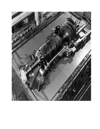
16. GAS TURBINE:
Gas Turbine is a Modern Power generating equipment. It takes the air
from atmosphere compresses it to sufficiently high pressure, same
pressurized air is then utilized for combustion, which takes place by in
combustion chamber by addition of fuel, there by hot combustion
products are generated which are expanded in the turbine where Heat
energy of hot combustion products is converted in to mechanical energy
of shaft which in turn utilized for generating power in Generator.
Compression is carried out by Axial Flow compressor, Heat addition is
done by Fuel in combustion chambers, Expansion of hot combustible
gases is carried out in Turbine and Burnt Gases are exhausted to
atmosphere or utilized for steam generation in GTs. All of these four
processes are carried out in only one Factory assembled Unit which is
called Gas Turbine. Drawing shows the typical Brayton cycle and also
shows the components of Gas Turbine. Gas Turbine operates on Brayton
Cycle. Brayton cycle is having divided in four segments namely
Compression, Heat addition, Expansion and Exhaust. In modern days
Gas Turbine Based power plants are becoming more and more popular
mainly because of its higher efficiency, Reliability, Quick response. In
the modern Power Plants Gas Turbine Exhaust is connected to Heat
Recovery Steam Generator where the steam is generated from hot gases
and Steam is utilized for running the Steam Turbine such system is
known as combined cycle power plants and where steam is utilized for
various processes such system is called as Co-generation system.
Normally combined cycle power plant efficiency is around 48-50 % and
co-generation system efficiency is around 80 % depending up on
application.
Reliance Petroleum Limited has 756 MW captive power plant, which we
can call a Combined Cycle Power Plant consists of 6 x 126 MW Frame-
9E (GE France) supplied by GE Energy Products France.
17. GT 3 & 4 have BLACK START Capabilities.
TYPE : PG 9171 E
GAS TURBINE APPLICATION : GENERATOR DRIVE
CYCLE : SIMPLE
TYPE OF OPERATION : BASE
ALTITUDE : Sea Level
COMPRESSOR : STAGES: 17 SPEED: 3000 R.P.M.
TURBINE : STAGES: 3 SPEED: 3000 R.P.M.
FUEL : Distillate/Gas Oil and Natural gas
POWER OUTPUT AT : 30 Deg C _ 112.7 MW, 43 Deg C 102.3
MW & ISO Cond 126MW
18. GAS TURBINE FUNCTIONAL DESCRIPTION:
When the turbine starting system is actuated and the clutch is engaged,
ambient air is drawn through the inlet plenum assembly, filtered, then
compressed in the 17th stage, axial flow compressor. For pulsation
protection during start-up, the 11th stage extraction valves are open and
the variable inlet guide vanes are in the closed position. When the speed
relay corresponding to 95 per cent speed actuates, the 11th stage
extraction bleed valves close automatically and the variable inlet guide
vane actuator energizes to open the inlet guide vanes to the normal
turbine operating position. Compressed air from the compressor flows
into the annular space surrounding the four-teen combustion chambers,
from which it flows into the spaces between the outer combustion
casings and the combustion liners. The fuel nozzles introduce the fuel
into each of the fourteen combustion chambers where it mixes with the
combustion air and is ignited by both (or one, which is sufficient) of the
two spark plugs. At the instant one or both of the two spark plugs
equipped combustion chambers is ignited, the remaining combustion
chambers are also ignited by crossfire tubes that connect the reaction
zones of the combustion chambers. After the turbine rotor approximates
operating speed, combustion chamber pressure causes the spark plugs to
retract to remove their electrodes from the hot flame zone. The hot gases
from the combustion chambers expand into the fourteen separate
transition pieces attached to the aft end of the combustion chamber liners
and flow towards the three stage turbine section of the machine. Each
stage consists of a row of fixed nozzles followed by a row of rotatable
turbine buckets. In each nozzle row, the kinetic energy of the jet is
increased, with an associated pressure drop, and in each following row
of moving buckets, a portion of the kinetic energy of the jet is absorbed
as useful work on the turbine rotor. After passing through the 3rd stage
buckets, the exhaust gases are directed into the exhaust hood and
diffuser which contains a series of turning vanes to turn the gases from
the axial direction to a radial direction, thereby minimizing exhaust hood
losses. Then, the gases pass into the exhaust. The resultant shaft rotation
is used to turn the generator rotor, and drive certain accessories.
19. GAS TURBINE CONSTRUCTION FEATURES –
Gas Turbine mainly divided in three section –
Compressor
Combustion system
Turbine
GAS TURBINE EQUIPMENT DATA SUMMARY
1. COMPRESSOR SECTION
Number of Compressor Stages : Seventeen (17)
Compressor Type : Axial Flow, Heavy
Duty
Casing Split : Horizontal, Flange
Inlet Guide Vanes Type : Modulated
The axial flow compressor is consisting compressor rotor and the
enclosing casing. The compressor casing consisting of Inlet Guide
vanes, 17 stages of rotor and stator balding, and 2 exit guide vanes. In
the compressor air is compressed in stages by series of alternate rotor
and stator airfoil-shaped blades. The rotor blade supply the force needed
to compress the air in each stage and stator blade guides the air so that it
enters the following rotor stage at proper angle. The compressed air exits
through the compressor discharge casing to the combustion chambers.
Air is extracted from the compressor for turbine cooling, bearing sealing
and during start-up pulsation control.
2. COMBUSTION SECTION
Type :Fourteen Multiple Combustors, Reverse
Flow Design
Fuel Nozzles : One Per Combustion Chamber
Spark Plugs : Two, Electrode Type. Spring-Injected Self
Retracting
20. The combustion system is the reverse flow type which includes 14
combustion chambers having the components like:
Combustion Liners
Flow sleeves
Transition pieces
Cross fire Tubes
Flame detectors
Fuel Nozzles
Spark plugs
Hot gases generated from burning the fuel in combustion chambers, are
used to drive the Turbine. The photograph shows outside look of
combustion system. In reverse flow system high pressure air from
compressor discharge is directed around the transition pieces and into
the annular spaces that surrounds each of 14 combustion liners.
Compressor discharge air which surrounds the liner, flows radially
inward through small holes in liner wall and impinges against rings that
brazed to liner wall. This air then flows right toward the liner discharge
end and forms a film of air that shields the liner wall from the hot
combustion gases. Fuel is supplied to each combustion chamber through
a nozzle that functions to disperse and mix the fuel with proper amount
of combustion air.
Combustion chambers - Discharge air from axial flow compressor
enters the combustion chambers from the cavity at the center of the
unit. The air flows upstream along the outside of combustion liner
towards liner cap. This air enters the combustion chamber reaction
zone through the fuel nozzle swirl tip and through metering holes
in both the cap and liner. The hot combustion gases from the
reaction zone passes through a thermal soaking zone and then in to
dilution zone where additional air is mixed with the combustion
21. gases. Metering holes in dilution zone allow the correct amount of
air to enter and cool the gases to the desired temperature. Along
the length of the combustion liner and in the liner cap are openings
whose function is to provide a film of air for cooling the walls of
the liner and cap. The transition pieces direct the hot gases from
the liners to the Turbine noz
Spark plugs - Combustion is initiated by means of the discharge
from two high voltage, retractable electrode spark-plugs installed
in adjacent combustion chambers. These spring -injected and
pressure retracted plugs receive their energy from ignition
transformers. At the time of firing, a spark at one or both of these
plugs ignites the combustion gases in the chamber, the gases the
remaining chambers are ignited by cross-fire through the tubes that
interconnect the reaction zones of remaining chambers. As rotor
speed increases, chambers pressure causes the spark plugs to
retract and the electrodes are removed from the combustion
zones.(spark plug locations at CC: 13 & 14)Ultraviolet flame
detectors - During the starting sequence , it is essential that an
indication of the absence of flame to be transmitted to control
system. For this reason, a flame monitoring system is used
consisting of four sensors which are installed on tow adjustment
combustion chambers and an electronic amplifier which is
mounted in the Turbine control panel. The ultraviolet flame sensor
consists of flame sensor, containing a gas filled detector. The Gas
within this flame sensor detector is sensitive to the presence of
ultraviolet radiation which is emitted by a hydrocarbon flame. A
DC voltage, supplied by amplifier, is impressed across the
detector terminals. If flame is present, the ionization of gas in the
detector allows conduction in the circuit which activates the
electronics to give an output defining flame. Conversely, the
absence of flame will generate an opposite output defining “No
flame ". The four flame detectors are located in the combustion
chamber No 4, 5, 10, and 11 out of total 14 combustion chambers.
22. Fuel nozzles - Each combustion chamber is equipped with a fuel
nozzle that emits a metered amount of fuel into the combustion
liner. Gases fuel is admitted directly into each chamber through
metering holes located at the outer edge of the swirl plate. When
liquid fuel is used, it is atomized in the nozzle swirl chamber by
means of high pressure air. The atomized fuel/air mixture is then
sprayed into the combustion zone. Action of the swirl tip imparts a
swirl to the combustion air with the result of more complete
combustion and essentially smoke free operation of the unit.
Crossfire tubes - The 14 combustion chambers are interconnected
by means of cross fire tubes, these crossfire tubes propagate the
flame to other combustion chambers.
GAS TURBINE FUELS - There are various kind of fuels can be fired in
the Gas Turbine, they are divided in two types
Liquid Fuels
High Speed Diesel ( HSD )
Light Distillate Oil ( LDO )
Light Cycle Oil ( LCO )
Naphtha
Kerosene
Gaseous Fuels
Natural Gas
Refinery Fuel Gas
LIQUID FUEL SPECIFICATIONS –
Specific Gravity of Fuel: The specific gravity indicates the
chemical composition of hydrocarbons. A distillate with low
23. specific gravity will be largely a paraffinic where as high specific
gravity will be high aromatics. The high aromatics has a greater
tendency to smoke. Specific gravity has an economic significance,
normally fuel is purchased by volume. The total heat value
decreases with the decreasing specific gravity. Washing of fuel
becomes difficult when specific gravity approaches to on higher
side i.e. near to the value of water.
Flash Point: It is the lowest temperature at which fuel produces
enough vapors to produce a flash in the presence of ignition
source. Flash point is the important from the fuel handling view
point, otherwise it is not critical to the turbine operation, It affects
the requirements of auxiliary equipment like motor , relay ,
heaters etc. i.e. they should be explosion proof. Naphtha has low
flash point, while HSD has comparatively high flash point. Lower
the flash point easier the burning of the fuel in Gas Turbine, hence
fuels having lower flash point is preferred.
Pour Point: It is the temperature of liquid where it starts flowing
freely. Pour point should be in the as minimum as possible
normally for HSD pour point is –20 deg C which is desirable.
Wax Content: Wax normally seen in heavy distillates. The wax is
the desirable fuel component from the stand point of high heat
content and high hydrogen content.
It can create problems in the fuel systems, it can clog the filters, or
it can clog the fuel transfer valve which needs high load for
change-over of filters, It can also clog the fuel lines, flow dividers,
warren pumps etc. The fuel contains high wax contents is normally
maintained at high temperatures to prevent the crystals clogging.
Viscosity: Viscosity of fuel is the measure of the fuel resistance to
flow, it is important in the fuel auxiliary equipment and it also
determines the pumping temperature, atomizing temperature and
24. fuel pressure. For the proper operation of the Gas Turbine
maximum viscosity of the fuel must not exceed 10 cst at 40 deg C ,
when this limit is exceeded the poor ignition , smoking ,
unsatisfactory combustion exit temperature , lower combustion
efficiency or formation of carbon etc. kinds of problems can occur.
Naphtha has the lowest viscosity, hence special kinds of
precautions are required. For maintaining sufficient viscosity,
heating of fuel is also one technique.
Sediments : Sediments in the fuel causes fouling in the fuel
handling system and also in Gas Turbine fuel system , hence they
should be kept as minimum as practicable
The sediments in the fuel can be gum, resins, asphaltic material,
carbon, scale, sand or mud. Poor handling of the fuel can increase
the level of sediments, i.e. poor washing of fuels, washing with
dirty water, improper blending etc. can lead to high concentration
of sediments. Normally gas turbine fuel systems are having with 5
microns filtration system which catches all dirt sediments etc.
Trace Metals: Trace metals are important to analyze from the view
point of deposition of particles on turbine internal parts. Normally
Sodium, Calcium, Potassium, Nickel and Vanadium and present in
the liquid fuels, these metals are causing hot corrosion in the Gas
Turbine components at the operating temperatures. These salts can
also form hard deposits on Gas Turbine blades, which are very
difficult to remove. Deposition of salt on turbine and nozzles lead
to reduced output of Gas Turbine. Sodium (Na), Potassium (K),
Calcium (Ca) are normally got separated by water washing process
and levels of these metals can be brought down to acceptable level.
But Nickel and Vanadium cannot be removed by water wash as
these metals are not soluble in water. These metals are present in
the complex oil soluble form. The corrosive effect of vanadium
can be prevented by suitable treatment of fuel by magnesium
additives. The magnesium compound inhibit the corrosive
characteristics of vanadium by forming high melting temperature
25. ash, consists of magnesium sulphate, magnesium oxide, and
vanadium pent oxides. Which are finally emitted along with
exhaust gases.
Boiling Range: Petroleum Products which consists of many
components do not have any specific boiling point, these products
have boiling range. The lowest temperature in the boiling range is
called as Initial Boiling Point (IBP). The maximum temperature
when all liquid is evaporated is the Final Boiling Point (FBP).
Sulphur Content: Sulphur is the highly corrosive substance in the
fuel. Sulphur reacts with fuel bound hydrogen and forms H2S (
Hydrogen sulfide ) which is poisonous gas which is harmful to
living substance , hence fuels having high sulphur contents are
normally emitted at very high level. Sulphur also reacts with
moisture and forms H2SO4 Sulfuric Acid at low stack temperatures
which is very corrosive. The stack temperatures are maintained at
sufficiently high enough to avoid stack corrosion.
3. TURBINE SECTION
Number of Turbine Stages : Three Single Shaft
Casing Splits : Horizontal
Nozzles : Fixed Area
The three stage turbine section is the area in which energy in the form of
high energy, pressurized gas produced by compressor and combustion
section is converted in to mechanical energy. The turbine rotor assembly
consists of two wheel shafts: the first, second, and third-stage turbine
wheels with buckets; and two turbine spacers. Concentricity control is
achieved with mating rabbets on the turbine wheels, wheel shafts, and
spacers. The wheels are held together with through bolts, Selective
positioning of rotor members is performed to minimize balance
26. corrections. The forward wheel shaft extends from the first-stage turbine
wheel to the aft flange of the compressor rotor assembly. The journal for
the no 02 bearing is a part of the wheel shaft. The aft wheel shaft
connects from the third-stage turbine wheel to the load coupling. It
includes no 03-bearing journal. Spacers between the first and second, and
between the second and third-stage turbine wheels determine the axial
position of the individual wheels. These spacers carry the diaphragm
sealing bands. The spacer forward face includes radial slots for cooling
air passages. The 1-2 spacer also has radial slots for cooling air passages
on the aft face. Turbine rotor must be cooled to maintain reasonable
operating temperatures and, therefore, assure a longer turbine service
life. Cooling is accomplished by means of a positive flow of cool air
radially outward through a space between the turbine wheel with buckets
and the stator, into the main gas stream. This area is called the wheel
space. The turbine rotor is cooled by means of a positive flow of
relatively cool (relative to hot gas path air) air extracted from the
compressor. Air extracted through the rotor, ahead of the compressor
17th stage, is used for cooling the 1st and 2nd stage buckets and the 2nd
stage aft and 3rd stage forward rotor wheel spaces. This air also
maintains the turbine wheels, turbine spacers, and wheel shaft at
approximately compressor discharge temperature to assure low steady
state thermal gradients thus ensuring long wheel life. The first stage
forward wheel space is cooled by air that passes through the high
pressure packing seal at the aft end compressor rotor. The 1st stage aft
and 2nd stage forward wheel spaces are cooled by compressor discharge
air that passes through the stage-1 shrouds and then radially inward
through the stage-2 nozzle vanes. The 3rd aft wheel space cooled by
cooling air that exits from the exhaust frame-cooling unit.
27. HEAT RECOVERY STEAM GENERATORS:
A heat recovery steam generator or HRSG is an energy recovery
heat exchanger that recovers heat from a hot gas stream. It
produces steam that can be used in a process (cogeneration) or
used to drive a steam turbine (combined cycle).
HRSGs are located in the downstream of GTs and produces
HP steam utilizing the GT exhaust gases. These HRSGs can
be run with or without supplementary firing according to the
steam demands. The total generating capacity of each HRSG
from 50% to base load of GT with supplementary firing is 315
TPH of HP steam at 3960C temperature and 49.3-kg/cm2
pressure.
These are horizontal, natural circulation, single drum, single
pressure, duct fired water tube type HRSGs. The capacity of
each HRSG in unfired mode at base load of GT is 218 TPH of
steam at above specified pressure and temperature.
28. Rated steam temperature in unfired mode is achievable above
60% of GT load, at the expected steam generation of about
142TPH.
HEAT RECOVERY STEAM GENERATORS FUNCTIONAL
DESCRIPTION:
The HRSG generates steam utilizing the energy in the exhaust flue
gas from the GT. Recent trends in the HRSG design include multiple
pressure units for maximum energy recovery, the use of high
temperature SH and auxiliary firing for efficient steam generation.
29. The quality and quantity of steam generates from HRSG depend on
the flow and temperature of the entering exhaust gas from GT.
GT can be run in open cycle with venting the exhaust gases to
atmosphere through the chimney but In this case the efficiency of the
system is very less and a lot of useful heat energy is wasted to the
atmosphere. So HRSGs are introduced at the down streamside of GT.
This mode of operation is called Co-generation mode (Fig. 1). In co-
generation mode steam generated is mainly used for process
requirements. But if the steam generated is used for further power
generation via Steam turbine then that cycle is called Combines cycle
operation (Fig. 2).
Each HRSG consists of preheater, economizers, evaporator, Drum and
Super heaters as major components. DM water before entering in to
the dearator pass through the preheater where it is pre heated. Feed
water from the boiler feed pump enters to economizers, flow through
economizer will increase the water temperature and this results in a
lower temperature at the stack inlet. The water then goes to the
drum, from drum flows to a down comer. At the bottom of the down
comer there are distribution pipes, which connect to all modules of
evaporator. The water in the evaporator will rise and change its phase
from water to vapor form and finally reaches the drum. In the drum
this saturated steam is separated from the water with the help of
cyclone separators. Strainers are also provided in the upper part of
the drum to prevent water droplets entering the super heater.
Saturated steam is then passing through super heaters in series with
attemperator in between. Attemperation is done through boiler feed
water itself. Other accessories of boiler include safety valves, soot
blowers, and blow down drum, emergency blow-down system, and
continuous blow down system, S0x/ N0x monitoring system and
steam & water analysis system.
30. CO-GENRATION MODE
Fig. 1
COMBINED CYCLE MODE
Fig. 2
COGENERATION MODE
COMPRESSOR GAS TURBINE
C
C
FUEL
GENERATOR
HRSG
HHP STEAM
FEED WATER
STACK
AIR
COMPRESSOR GAS TURBINE
C
C
FUEL
HRSG
FEED WATER
STACK
AIR
STG
EXTRACTION CONDENSATE
GENERATOR
GENERATOR HHP STEAM
COMPRESSOR GAS TURBINE
C
C
FUEL
HRSG
FEED WATER
STACK
AIR
STG
EXTRACTION CONDENSATE
GENERATOR
GENERATOR HHP STEAM
32. 1. STEAM TURBINES:-
CPP has 6 identical steam turbines. Steam turbine is single shaft, axial flow,
single cylinder and condensing type impulse reaction turbine with two stage
extractions at different pressure. The turbine has three sections called HP
section, MP section and LP section. HP section has 7 stages of rotating blades,
MP section has 8 stages of rotating blades and LP section has 16 stages of
rotating blades. All the three sections are housed in a single cylinder.
Maximum flow limit is given to protect the steam turbine against overloading.
Extraction pressure high and low trips are provided to protect turbine against
overloading. To ensure the blade cooling of different sections of the turbine,
required minimum flow through each of the turbine section blades must be
maintained. The turbine is having single shaft supported by two journal
bearings at each end and held axially by double acting tilting type thrust
bearing. The bearings are forced feed lubrication type. The turbine casing is
horizontally split and via two brackets integrally cast to the casing top part,
rests on the bearing housing. The bearing housing rests on supports and is
guided axially by longitudinal keys on the foundation such that to allow
thermal expansion in axial direction. The turbine exhaust end is bolted to
condenser. An expansion bellow is provided between turbine and condenserto
take care of the thermal expansion. The exhaust steam casing rests on laterally
arranged bracket supports to which it is axially fixed such that transverse
expansion is not restricted. Drawing shows line diagram of turbine with
design values.
33. 2. PRESSURE REDUCING AND DESUPERHEATING STATIONS: -
Six pressure reducing / de-superheating stations are provided to supply HP,
MP & LP steam for the refinery process plants. One pressure reducing / de-
superheating station is provided for initial start up of the HRSGs / Aux.
Boilers. The PRDS system is sized to provide redundancy for meeting refinery
steam demand for limited failure or non-availability of the steam turbine. The
PRDS is sized to meet the demand normally met by two steam turbines on the
basis that one trips while another is out of service for the maintenance. All let
down stations and de superheating stations are located adjacent to the north
wall of steam turbine building.
AUXILLARY BOILER:
There are four auxiliary boilers in Reliance Jamnagar JERP CPP. They are
supplied by M/S Thermax India Ltd. They have a capacity of supplying 275 t/hr of
steam at 49.3 kg /cm2 and 397 + / - 5 OC. These boilers will normally be operated
at 90 t/hr load and ready to ramp up to MCR (Maximum Continuous Rating) in
case of disturbance in steam supply. The auxiliary boilers are designed for the
combustion of fuel oil and refinery fuel gas (dual fuel). These boilers are mainly
designed to supply steam for the safe shut down of the refinery in the event of total
power failure. So it is imperative that the boiler operation not only be efficient but
also reliable. The support system of the boiler has to be equally reliable to face
such an eventuality (meaning, turbine drives for fuel oil pumps, forced draft air fan
and emergency instrument air supply).
The Auxiliary Boiler here is a water tube, forced draft, natural circulation, bottom
supported, bi drum and four pass boiler.
Boilers can be classified as a water tube or a fire tube boiler depending upon
whether the flue gas or water is passing through the boiler tubes. In a fire tube
boiler the flue gas passes through the boiler tubes and water surrounds the tubes.
Hence the name fire tube boilers. The locomotive engine is a fine example of this.
But these boilers are not available in the higher capacity ranges owing to their
design limitations. Whereas in the water tube boiler, the water passes through the
tubes and the flue gas envelopes the water tubes. And hence the name water tube
boilers. Owing to their design the water tube boilers are available.
35. In higher capacities of pressures and steam flow. The JERP Auxiliary boiler is a
water tube boiler. The flue gases in the auxiliary boilers pass through an enclosure
of water tube panels that is called the furnace.
Boiler can be classified as induced, forced or balanced depending upon the nature
of admission of air and exit of flue gasses in the boiler. In a forced draft boiler the
fan that supplies air to the boiler is located in the up-stream direction of the boiler.
The figure 1 gives a clear indication of the forced draft system. It is termed as
forced draft as the air is forced into the system (boiler). The induced draft boilers
have a fan at the downstream end of the boiler. In this the air and flue gases are
induced in and out of the boiler respectively. The balanced draft boiler have both,
the forced draft fan that forces air into the boiler and induced draft fan that induces
or sucks out the flue gases from the boiler and throws them in to the stack. Boilers
burning solid fuel and of higher capacities are of balanced type (mainly because, in
solid fuel firing boilers the Increment in flue gas volume is higher as compared to
gas fired or oil fired boilers). Induced draft type boilers are of lower capacity. As
the auxiliary boiler burns liquid and gas fuel the forced draft system in it is
adequate enough to force in the air required for combustion and force out the flue
gases after combustion.
Boilers can be either supported at the top or bottom. The water walls of top
supported boilers are hung or suspended from the top. These types of boilers
expand downwards. The structures for these types of boilers are heavier and hence
higher initial cost is incurred. The bottom-supported boiler expands upwards. The
membrane walls are not hung (supported) from the top but are supported at the
bottom. The Auxiliary boiler is a bottom supported type. The initial cost, as
compared to that of the top supported boiler is lesser owing to lighter supports.
The water circulation in the boiler is either natural or forced. Meaning, the
circulation is based upon the density difference arising due to the heat generated
from burners. The water that is in the tubes located away from the burner zone is
colder and hence is heavier. They are heavier in comparison to the water in the
tubes that is closer to the burner zone. It shows Natural circulation in a boiler.
(Arrows represent direction of water flow).The illustration clearly indicates that the
water wall that is furthest away from the burner is colder. Hence the water in it is
heavier. This causes a downward flow. Whereas the water wall that is closer to the
burner is hotter and hence the water in it is lighter. Hence the upward flow is
established. In this way owing to density difference there is natural circulation of
water from the drum and back to the drum. This type of circulation is termed as
natural circulation. But this density difference ceases for boilers operating at
36. pressures greater than 220.9 atmospheres, At this pressure the difference in density
(between water vapor and water) is zero. For circulation of water in such boilers an
external energy in the form of a pump is required to establish circulation within the
boiler. Such boilers are called forced circulation boilers. The auxiliary boilers at
CPP are of “natural circulation type.
Auxiliary boiler is a bi-drum boiler if it has two drums namely Steam drum and
Mud drum or bottom drum. The bi-drum boilers cannot ramp as fast as the single
drum. This is because the drums are directly in the flue gas path. Because of this,
they undergo a lot of thermal stress during ramping. The single drum boilers ramp
up faster because, the single drum is outside the flue gas path and hence lesser
thermal stresses. The time taken for alkali boil out for a bi-drum boiler is lesser as
compared to the single drum boiler. Because most of the debris to be removed after
alkali boil out is done by opening the mud drum manholes in case of a bi-drum
boiler.
The boiler is a water tube boiler, forced draft, bi-drum, bottom supported, and
natural circulation type of boiler. It is a water tube type of boiler as the water is in
the tube and the flue gasses are outside it. The boiler is forced draft because there
is a positive draught in the furnace and the exit of the flue gases is dependent on
the draught created by the temperature differences of flue gas and air and also
because of the height of the chimney. The boiler is supported at the bottom and
therefore the expansion of the boiler is upwards i.e. vertical. The main advantage
of such a (bottom supported) design is the reduction in the capital cost needed
towards the heavier support structure which would have been needed if the boiler
was to expand downward (as in case of top supported or freely hanging boilers)
direction. The water circulation in the boiler is natural meaning no external force is
required for inward movement or travel in the boiler.
CPP Boiler Design Parameters
The boiler has been designed for site conditions having a maximum dry bulb
temperature of 43 deg. C and maximum wet bulb temperature of 28 deg. C. The
design surface temperature is at 65 deg. C. the boiler is designed for a max. RH
(Relative Humidity) of 92.8 % and a minimum RH of 27 %.Evaporation capacity
of the boiler is 275 t/hr. Out let superheated steam at a pressure of 49.3 kg / cm sq.
and 397 + / _ 5 O C. The total surface area of the boiler is 9499 sq. meters. The
auxiliary boiler has been designed for earthquake of class three type. The boiler
has six burners which are mounted in the front wall of the furnace. These burners
37. are of dual type as they are capable of burning fuel oil and fuel gas. The boiler has
a turn down ratio of 1: 4. The boiler being a forced draft one has two forced draft
fans (2 x 100 %). It also has two scanner fans (2 x 100 %) which help in sealing
and cooling peep holes, soot blowers and scanners. Two phosphate dosing pumps
help in maintaining the water quality of the boiler. The boiler has three super
heaters. The super heaters help in increasing the temperature of steam from
saturation point. There is a single attemperator that helps in controlling the steam
outlet temperature at any load. The attemperator is of a spray type.
The super heater has three passes. The attemperator is situated between the second
and the third pass. The boiler consists of two economizers 1A and 1B. The
economizers boost up the feed water temperatures by absorbing heat from the flue
gases. There is also a drum coil pre- heater (DCPH), situated in the mud drum,
which plays an important role in control of flue gas exit temperature.
Soot blower is a device for removing the sootthat is deposited on the furnace tubes
of a boiler during combustion. There are twenty seven numbers of soot blowers of
which three are located in the super heater zone, twelve in the convective bank or
generating bank zone and twelve in the economizer zone. The boiler consumes HP
steam to the tune of around 5.5 TPH in the turbine driven FD fan, MP steam in
soot blowers and burners for atomizing steam (1.4 t/hr – 10.6 t/hr). The boiler also
consumes LP steam for oil tracing. The boiler uses dry air at a pressure of 7 – 8
kg/cm sq for pneumatic valves and for emergency cooling of scanners in case of
total power failure. The boiler motor driven fan consumes a maximum of around
325 KW power at 6.6 KV.
AUXILLARY BOILER FUNCTIONAL DESCRIPTION:
The Boiler is divided into a furnace section and a second pass by a division
membrane wall. The furnace section is made by tube walls and refractory wall. The
furnace comprises of the furnace side wall, roof, floor & rear walls and the front
refractory wall. The furnace side, roof and floor, rear walls are of membrane panel
construction. The furnace front wall is of refractory construction. The second part
comprise the super heater, convection bank tubes. The second pass is enclosed by
the rear wall & boiler side wall. Entire array of tubes in the furnace and second
pass is designed for convective heat transfer and is fully drainable. Feed water
from plant is admitted to the drum coil heater and then to the economizer through a
feed water control station. The feed water is then feed led to the steam drum.
Steam is generated in the convective bank tubes. In the riser tubes partial
38. evaporation takes place due to heating. The resulting water stream mixture returns
drum where the separation of the steam from water takes place. The saturated
steam is led to the super heater and then through the main steam stop valve to the
process plant.
Combustion of fuel takes place in the furnace with the help of the burner mounted
on the furnace front refractory wall. Combustion air is sucked from the plant
environment by the FD fan. Flue gases generated are passed through the
convection bank and is led to the economizer through the flue gases duct and
finally through the steel stack into the atmosphere. Six burner are provided on the
burner front wall in three elevations for burning fuel oil and gas. The starting and
stopping are monitored by the PLC based burner management system. DCS based
controllers are provided by the contractor for the control loops. Six long retractable
and nine rotary soot blowers are provided in the second pass and twelve short
retractable soot blower are provided for economizer to periodically clean the soot
and other deposits which may accumulate in the super heater, boiler tanks and
economizer surface when the burner are in service. Soot blowing is done to keep
up the heat transfer efficiency at maximum level. Safety walls have been provided
in the drum and in the main stream line of the boiler. Suitable insulation around the
drum and the membrane panels, steam lines, feed water lines, hot air and flue ducts
have been provided to minimize heat loss and for operators safety.
BALANCE OF PLANT TRAINING:
The balance of plant system of the CPP consists of the following parts:
5. Compressed Air System
6. Demineralised Water (DM Water) System
7. Deaerator System
8. Feed Water System
9. Chemical Dosing System
10. Nitrogen System
39. 1. COMPRESSED AIR SYSTEM
CPP has an instrument air system which provides bothinstrument and plant air.
All air supply will be oil free. Plant air is distributed from the receiver
dried to the various Utility Stations.
COMPRESSED AIR SYSTEM DESIGN:
Air Compressor - 2 Nos.
Capacity: - 2421 Nm3/hr
Discharge Pressure/temperature: - 10.2 kg/cm2, 36oc
Driver: - 380 KW, 6.6 KV
Plant Air Receiver – 1 Nos.
Capacity: - 20.0m3
Design Pressure/temperature: - 15 kg/cm2, 65oc
Instrument Air Dryer Skid - 1 Nos.
Pressure/temperature: - 15 kg/cm2, 65oc
Normal flow rate: - 1600 Nm3/hr
Operating pressure/temperature: - 10 kg/cm2, 40oc
Instrument Air Receiver – 2 Nos.
Capacity: - 60.0m3 each
Design Pressure/temperature: - 15 kg/cm2, 65oc
COMPRESSED AIR SYSTEM FUNCTIONAL DESCRIPTION:
Both the compressors are Screw compressors of non-lubricated type.
Compressor skid consists of a lube oil pump and its cooler within the
base plate limit. Compressors are of two stages with an intercooler in
between in order to get high compression ratio and efficiency. A motor
driven auxiliary startup pump is provided for each unit .Its operation is a
part of the startup sequence such that compressor drive motor is only
energized once the compressor oil pressure has reached the required
setting. There are two dryers installed for drying of wet air discharged
40. from compressor packages. Each compressor package outlet air goes
through the respective dryer and the common outlet is routed to
Instrument air receivers. Both air dryers are of adsorption type. Dryers
can operate either on timer or dew point control. In a two stage
compressor about 45% of the energy is lost in the after cooler. This
energy is used as a source of hot air in adsorption air drying system. In
an adsorption dryer there are two factors to be considered, one is
adsorption and the other is regeneration. In adsorption the air goes
through an activated bed where moisture is adsorbed and air goes out in
regeneration we bring the desiccant back to its original adsorption
capacity so that it can be reused in the next cycle by flowing a stream of
hot air through the bed.
2. DEMINERALISED WATER (DM WATER) SYSTEM:
41. Each Demineralised Water Storage Tank will be supplied with three
100% pumps (one motor and one turbine driven operating, one motor
driven standby), making up the feed to the CPP deaerators via the HRSG
condensate Preheater sections. The DM water tanks receive DM water
from utility on continuous basis. Apart from DM water deaerator feed
pumps spill back also comes back to DM water tanks. The deaerator
feed pumps supply DM water to deaerators. Demineralised water is
produced in the Water Treatment Plant (WTP) portion of the refinery
Utility Block. Output from the WTP will be pumped to the CPP
Demineralised Water Storage Tanks. Two tanks will be provided for the
CPP demand. This provides the required minimum level of capacity to
allow for upset conditions or problems in reaching water spec. within the
WTP. The principle requirement is high purity low conductivity water
suitable for use in the CPP high pressure boilers and for water injection
into the Gas Turbines for NOx control.
DM water tanks (2 Nos.)
Size: - 36 M x 20 M height
Gross capacity: - 20350 M3 (each)
Operating temperature: - 450c
Design pressureand temperature: - 18.1 kg/cm2, 65 oc
Hydro test Pressure: - 29.1 kg/cm2
Deaerator Feed pumps (9 Nos.)
Normal flow: - 587.9m3/hr.
Pump discharge pressure: - s 15.7 kg/cm2 abs.
Rated suction pressure: - 1.1kg/cm2
NPSH required: - 3.5 meter of water
Working temperature Normal: - 45 deg C
Maximum temperature: - 65 deg c
Minimum continuous flow: - 225 m3/hr
Pump speed: - 1480 rpm
Hydraulic power: – 308 kW
Driver motor: - 371.77 kW
Driver: -1500 rpm
42. DEMINERALISED WATER SYSTEM FUNCTIONAL
DESCRIPTION:
DM Water tanks:
The DM water tanks are vertical cylindrical with truss supported cone
roof type of tanks. On tank overflow line of 24 inch diameter is also
provided which extends to ground level. Two atmospheric vents of 8
inch diameter are provided to protect the tank from pressurization and
vacuum. The pumping IN and pumping OUT rate of the tank is 2300
m3/hr. Each tank will be provided with nitrogen blanketing to limit and
control the amount of dissolved oxygen in the Demineralised water. The
nitrogen for blanketing will be provided from the refinery utilities block.
Deaerator Feed Pumps:
To supply DM water to deaerators, each DM tank is provided two motor
driven and one turbo driven deaerator feed pumps. Process deaerator
feed pumps are connected with both the tanks through a common
header. So there are total nine deaerator feed pumps each of capacity
794m3/hr design flow. The DM water from utility is supplied to both
tanks, DM water level control valves LV410 and LV420 maintains the
DM water tank levels , normally 18.00meters as the set point is given by
panel engineer. However on both these controllers, 10% minimum open
locking is provided to protect the utility DM water supply pump
operating against shut off pressure.
44. There are 3 deaerators each sized for 750 TPH. The deaerators receive
feed water makeup from the Demineralised Water Storage Tanks. Prior
to the deaerators, the feed water is routed through the condensate
preheater sections of the HRSGs. The pre heater serves to preheat the
feed water, reducing the amount of LP steam required for deaeration and
improving cycle efficiency. A spare deaerator is located between the
deaerators and the Process deaerators that serve the refinery process feed
water system. This swing deaerator can be valve into service on either
the side or the Process Feed water to allow inspection, maintenance or
repair of a deaerator without impacting operation of either system. There
are 3 process deaerators each sized for 750 TPH. The process deaerators
receive feed water from the process condensate by utility. Located at the
same elevation and alongside the deaerators are three further deaerators
which have no function for CPP but are dedicated to supply of feed
water to the refinery process. The deaerators are installed at a suitable
location to ensure the minimum NPSH requirement of the BFP's is
achieved. The deaerators serving the refinery are to be mounted adjacent
to the deaerators and are to be of similar size. The spare deaerator is a
common spare. Selection of this location rationalizes steam pipe routing
and minimizes cost by permitting use of a single spare deaerator to cover
removal from service of either a CPP or Process Deaerator. This
arrangement avoids the need to construct separate supporting steelwork
and assists in lying out and support of the pump suction and discharge
manifolds. The Process boiler feed water system is ideally isolated from
the feed water supply to prevent potential contamination of feed water.
However, a cross connection will be provided to allow Demineralised
water to feed the process deaerators under upset conditions. Similarly, a
separate cross connection will be provided to allow condensate return to
feed the deaerators under upset conditions, but only if the condensate
returns is of Demineralised water quality.
45.
46. DEAERATION SYSTEM FUNCTIONAL DESCRIPTION:
Deaeration is process to remove non condensable gases from the water.
To remove non-condensable gases from water, the water temperature
must be raised to the boiling point. The solubility of the gases is
dependent upon the temperature of the water. When the temperature of
the water is at the boiling point for the operating pressure, the solubility
of the gases is zero. In order to escape insoluble gases from the mass of
the water, the gas must diffuse through the surface film surrounding the
particle of the water. Repeated agitation and breaking up of the water by
passing it through spray and over trays and through a steam atmosphere
causes rapid diffusion and elimination of the gases. Deaerator is an
equipment used for the Deaeration of the boiler feed water. DM water is
supplied to deaerator through deaerator feed water pump. LLP steam is
used for the deaeration, which is taken through heat recovery system and
by desuperheating the LP steam to 1.2-1.5 kgcm2. Process deaerator get
the feed water from the process condensate from utility.
47. 4. FEED WATER SYSTEM:
The conceptual design includes for common boiler feed water pumps
and deaerators for supply of feed water to all HRSGs and Auxiliary
Boilers. It is intended to utilize 3 deaerators and 3 BFWPs sized to meet
the full boiler feed water flow requirements. Boiler feed water is also
supplied to the HP/MP and MP/LP Pressure Reducing Stations and all
boiler attemporators for desuperheating. The design basis for sizing the
deaerators and BFP's is the requirement that there should be no boiler
trip leading to interruption in steam output during transients caused by
an upset condition resulting in tripping of a BFP or deaerator. The
transient upset condition will be of relatively short duration as the
control system will automatically start the standby pump. Process heat
developed in various refinery units is utilized to generate steam. For
steam generation, process units required feed water at different
condition. The design basis of the BOP - CPP is developed for overall
summary of refinery requirement for power, steam, process feed water,
condensate, desalination water, and cooling water. Three dedicated
Process Condensate Deaerators are provided within the CPP. Three sets
of BFWP (i.e. HP, MP and LP pressure levels) are provided to pump
feed water back to the Refinery. In order to ensure safe shutdown of the
FCC and other critical process units, two of the BFW pumps are turbine
driven, the others are motor driven. Normal operation would be with two
turbine pumps in service with one electric if demand warranted running
a third pump. This combination provides the advantage of rapid run up
characteristic of an electric pump, following the trip of any running
pump. All CPP deaerators and pumps are manifold together under
normal service conditions.
48. FEED WATER SYSTEM FUNCTIONAL DESCRIPTION:
A centrifugal pump is one of the simplest pieces of equipment in any
process plant. Its purpose is to convert energy of a prime mover (an
electric motor or turbine) first into velocity or kinetic energy and then
into pressure energy of a fluid that is being pumped. The energy changes
occur by virtue of two main parts of the pump, the impeller and the
volute or diffuser. The impeller is the rotating part that converts driver
energy into the kinetic energy. The volute or diffuser is the stationary
part that converts the kinetic energy into pressure energy. The process
liquid enters the suction nozzle and then into eye (center) of a revolving
device known as an impeller. When the impeller rotates, it spins the
liquid sitting in the cavities between the vanes outward and provides
centrifugal acceleration. As liquid leaves the eye of the impeller a low-
pressure area is created causing more liquid to flow toward the inlet.
Because the impeller blades are curved, the fluid is pushed in a
tangential and radial direction by the centrifugal force. This force acting
inside the pump is the same one that keeps water inside a bucket that is
rotating at the end of a string.
49. CONCLUSION
As stated in my report the SEZ CPP is the power hub of JERP. It is capable of
supplying sufficient power to this plant as well as to DTA plant. It incorporates
both, the generation and the distribution systems of the plant.
The plant has the most advanced world class systems as per the needs. It has been
designed with the environmental sustainability and protection in mind. The well
maintenance and proper protection of the machines is always taken care of. The
safety is always considered the first priority in RIL.
I have gained a lot of knowledge in the field of electrical industrial applications.
I’m very much thankful to the finest industrial systems and the friendly and most
organized working environment in RIL which has transformed my mere theoretical
knowledge into solid understanding which is sure to be helpful throughout my life.