3. Lecture-6
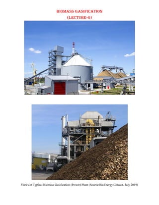
BIOMASS GASIFICATION
(Lecture-6)
Biomass Feedstock for Gasification
biomass feedstocks are classified based on several factors, such as : moisture content,
material, and form as shown in Table-1.
biomass is broadly divided into three groups: dry, wet, and others
dry biomass is classified as woody or herbaceous and wet biomass as sludge/excreta,
common food, or other
each classification has three sub-categories: waste, unutilized, and produced
Table-1: Classification of Biomass Feedstocks
among these, dry woody/herbaceous biomasses are used as feedstocks for BG plants in
Japan
woody biomasses contain waste woods (construction wastes and timber off cuts) and
unutilized woods (forest thinning, remaining timbers, and damaged trees) composed of
cedar, cypress, pine, etc.
short-rotation woody crops (eucalyptus, willow, etc.) are categorized as produced woods
energy crops such as willow may be cultivated in land fallow and used as biomass
for unutilized herbaceous biomass, crop residues such as rice/wheat straw and rice husks
while for produced herbaceous biomass, grasses such as Napier grass, sorghum, and
Miscanthus are usable
above all, rice husks contain abundant silica
the ash byproduct from gasifiers has potential use in nanomaterials
Chemistry of Gasification
the reactions taking place in the gasifier can be summarized as given below:
Partial oxidation:
C + O2 ↔ CO ΔH = − 268 kJ/mol (1)
Complete oxidation:
C+O2 ↔ CO2 ΔH = − 406 kJ/mol (2)
Water gas phase reaction:
Page-2
4. Lecture-6
C + H2O ↔ CO + H2 ΔH = 118 kJ/mol (3)
Boudouard reaction:
C + CO2 ↔ 2CO ΔH = 170.7 kJ/mol (4)
the heat required for water gas phase and Boudouard reactions is provided by complete
and partial oxidation reactions, and complete oxidation provides around 60% of the heat
requirements during gasification
in addition to the previous reactions that are common in combustion and gasification,
hydrogen, steam, and carbon monoxide undergo further reactions as shown below:
Water gas shift reaction:
CO + H2O ↔ CO2 + H2 ΔH = − 42 kJ/mol (5)
Methane formation:
CO + 3H2 ↔ CH4 + H2O ΔH = − 88 kJ/mol (6)
the water gas shift and methane formation reactions are in equilibrium and the governing
parameters are: pressure, temperature, and concentration of reaction species
the possible gasification reaction may also be summarized and shown by the following
diagram
Overall Steps Involved in Biomass Gasification
the main steps involved can be categorized as upstream processing, the gasification
process in the gasifier and the downstream processing as shown in Figure-1
Upstream Processing
upstream processing includes processing of the biomass to make it suitable for
gasification operations
size reduction is needed to obtain appropriate particle sizes
drying is needed to achieve appropriate moisture so that the process can work efficiently
densification also may be necessary due to the low density of biomass
Gasification
this is the second step where the gasification process is carried out under specified
conditions in order to achieve optimum product yield, i.e. the producer gas
different types of gasifiers are used for the purpose
Down Stream Processing
Page-3
5. Lecture-6
this is the third step where the cleaning (purification ) of the gaseuos products take place
as per the desired sopecifications
unit operations are applied foe the purpose
Figure-1: Processes involved in overall biomass gasification.
The Biomass Gasification Process (Mechanisms of Gasification)
the biomass gasification process consists in the conversion of a solid/liquid organic
compound in a gas/vapor phase and a solid phase
the principal reactions of gasification are endothermic and the necessary energy for their
occurrence is, generally, granted by the oxidation of part of the biomass, through an allo-
thermal or an autothermal phase
in the auto-thermal process, the gasifier is internally heated through partial combustion,
while in the allo-thermal process the energy required for the gasification is supplied
externally
considering the auto-thermal system, gasification can be seen as a sequence of several
stages
a simplified schematic representation of the gasification is demonstrated in Figure-2
the main steps of the gasification process are:
i. oxidation (exothermic stage)
ii. drying (endothermic stage)
iii. pyrolysis (endothermic stage)
iv. reduction (endothermic stage)
Figure-2: Main stages of the gasification process.
Page-4
6. Lecture-6
Oxidation
in order to obtain the thermal energy required for the endothermic reaction and to
maintain the operative temperature, the oxidation of part of the biomass is necessary
the oxidation is carried out in conditions of lack of oxygen with respect to the
stoichiometric requirement
despite the partial oxidation involving all carbonaceous species (tars included), it is
possible to simplify the system considering that only char and the hydrogen contained
in the gas produced participate in the partial oxidation
the main reactions that take place during the oxidation phase are given in Figure-2
and also discussed in the chemistry of biomass gasification
as evident, the main product of this step is the thermal energy necessary for the whole
process, while the combustion product is a gas mixture of CO, CO2 and water
in this mixture nitrogen can be present if the biomass oxidation is performed with air,
otherwise nitrogen is practically absent if only oxygen is used
Drying
drying consists in the evaporation of the moisture contained in the feedstock
the amount of heat required in this stage is proportional to the feedstock moisture
content
generally, the heat required derives from the other stages of the process
drying can be considered complete when a biomass temperature of 150 °C is achieved
Pyrolysis
pyrolysis leads to the thermochemical decomposition of the matrix carbonaceous
materials
the cracking of chemical bonds takes place with the formation of molecules with a
lower molecular weight
by pyrolysis, it is possible to obtain different fractions: a solid, a liquid/condensed gas
and non-condensed gas
the solid fraction, which can range from 5–10 wt% for fluidized bed gasifiers to 20–
25 wt% for fixed bed gasifiers, has a high carbon content and is characterized by a
high heating value
the solid fraction includes the inert materials contained in the biomass in the form of
ashes and a high carbon content fraction, called “char”
the liquid fraction, usually called "tars", varies according to the gasifier type, such as
lower than 1 wt% for downdraft gasifiers, 1– 5 wt% for bubbling bed gasifiers, 10–20
wt% for updraft gasifiers and
is constituted by complex organic substances, condensable at relatively low
temperatures
the gaseous fraction is typically 70–90 wt% of the fed material and is a mixture of
gases that are non-condensable at ambient temperature
the gaseous fraction is called "pyrolysis gas" and consists mainly of hydrogen, carbon
monoxide, carbon dioxide and light hydrocarbons such as methane and other C2, C3
hydrocarbons; minor constituents are acid or inert gases
the pyrolysis reactions take place with a temperature in the range 250–700 °C
they are endothermic and, as in the drying step, the heat required comes from the
oxidation stage of the process
Page-5
7. Lecture-6
Reduction
the reduction step involves all the products of the preceding stages of pyrolysis and
oxidation
the gas mixture and the char react with each other resulting in the formation of the
final gaseous mixture
main reactions occurring in the reduction step have been shown in ‘Chemistry of
Biomass Gasification’ and also demonstrated in Figure-2
Conceptual diagram with respect to the mechanism of gasification demonstrated in
multiple steps fixed-bed (a) updraft and (b) downdraft gasifiers
Figure-3: Conceptual diagram of multiple steps in fixed-bed (a) updraft and (b)
downdraft gasifiers
Factors Affecting the Gasification Process
the biomass gasification units may be divided into small-, medium-, and large-scale
biomass gasification and power generation units
pretreatment of biomass is needed which includes size reduction, size screening,
separation of magnetic materials, and storing as wet biomass
then prior to gasification, drying and storing as dry material are accomplished to reduce
the moisture content
feedstock type and feedstock preparation are important factors affecting the yield and
quality of produced gaseous mixture or the syngas
shredding and drying are two processes conducted to prepare the biomass raw material
for gasification process
the main parameters affecting the gasification are: equivalence ratio (ER), biomass
characteristics, moisture content, moisture content, Superficial velocity, Operating
temperature, gasifying agent, residence time, pressure, catalyst, effect of biomass/steam
ratio
Page-6
8. Lecture-6
Equivalence Ratio (ER)
the equivalence ratio (ER), Φ is defined as the ratio of the actual air supplied to that
of the stoichiometric/theoretical air used for gasification, i.e.
Combustion
for
Air
of
t
requiremen
metric
l/Stoichio
Theoretica
Combustion
for
System
the
to
supplied
Air
Actual
Φ
the efficiency, of a gasifier is defined as
Biomass
the
from
input
Energy
C
Gasat15
Producer
dry
the
in
output
energy
Chemical 0
it may be seen from the following Figure-4 that total energy in the gaseous phase
increases with the increase of equivalence ration, Φ .
Figure-4: Producer gas composition with variable stoichiometric variation.
increasing ER decreases the heating value of the produced gas due to decreasing H2
and CO concentration and increasing CO2 concentration
higher ER helps in reducing tars and provides more O2 to react with volatiles
typical values of ER ranges between 0.2 and 0.4.
it was reported that increasing ER decreases the concentration of combustible gases
CO, CH4, and CnHm, however H2 increases till the value goes to 0.4 and then it
decreases
increasing ER improves the reaction temperature and carbon conversion, and reduces
the tar yield
Biomass Characteristic
biomass characteristic is a major factor affecting produced gases during gasification
the physical properties that may have major effect are: absolute and bulk density, and
particulate size
Page-7
9. Lecture-6
the chemical composition parameters that are of major importance to define the
quality including volatile matter, moisture content, fixed carbon, ash content, and
gross calorific
the ultimate analysis comprises the carbon, oxygen, nitrogen, and sulfur of the dry
biomass on a weight% are also highly significant
Moisture Content
the moisture content can be determined by complete drying of biomass sample
the moisture content is calculated by subtracting the sample weight after drying from
fresh sample weight
maximum allowable moisture content in downdraft gasifier is 40% on dry weight
basis
updraft gasifier can handle biomass with higher moisture content
the higher moisture content in biomass will increase the consumed energy for drying,
and will reduce the pyrolysis of biomass
as a general rule, increasing moisture content decreases the conversion
Superficial Velocity
it is the ratio of the biogas production rate at normal conditions and the narrowest
cross-sectional area of gasifier
lower superficial velocity is linked with high yield of char, and large quantities of
unburned tars, which may deactivate catalyst, plug lines, and destroy compressors
higher superficial velocity results in reduced amount of char and low overall process
efficiency
Operating Temperature
operating temperature affects conversion, tar content, gas composition, gas heating
value, and char conversion
in order to select the optimum temperature, gasifier type, and biomass source is
considered
generally, temperature higher than 800°C should be used to obtain high conversion
and low tar content in the produced biogas
low temperature is associated with low tar content, low H2 and CO content in the
produced biogas
increasing temperature will increase gas yield, hydrogen, heating value, and ash
agglomeration
the ash agglomeration problem can be overcome by keeping the temperature below
750°C
Gasifying Agent
gasifying agents in use are air, steam, steam/oxygen mixture, and CO2
they affect the heating value of the produced gas
the heating value increases with increasing steam content of the gasifying agent,
whereas heating value decreases as air increases in the gasifying agent
the steam/oxygen mixture represents a zero nitrogen-gasifying agent which increases
the heating value and allows liquefying the produced gas after proper treatment
Residence Time
it has a significant impact on the composition and produced tars in biomass
gasification
oxygen-containing compounds may be decreased by increasing the residence time
Page-8
10. Lecture-6
increasing residence time decreases yield of one and two atomic ring compounds,
Pressure
in gasification processes, either atmospheric or and higher pressures are commonly
used
selection of the optimum pressure depends on the application of the produced gaseous
product
if it is used for production of methanol or synthetic auto-fuels, higher pressures are
preferred to improve the process yield and to reduce tar content
for generating burnable gases, atmospheric pressure should be used
high pressure applications are recommended for large scale gasification
however, atmospheric pressure is recommended for small-scale gasification
high pressure gasification is still not well developed and further research is needed to
commercialize such processes
Catalyst
The type of the catalyst is an important factor affecting gasification quality and the
product
catalyst affects the composition of the syngas by manipulating the percentage volume
of hydrogen, carbon dioxide, methane, and carbon monoxide
optimum quantity of catalyst plays a significant role in minimizing the gas content of
carbon dioxide and maximizing the useful gases in the gaseous products such as
hydrogen, carbon monoxide, and methane
Technologies of Biomass Gasification
Introduction
gasification process converts biomass, a low-energy density material, into a gaseous
product mixture containing mainly CO, H2, CH4 and CO2 .
gasification is a partial oxidation process and it is commonly operated at 800–900 0
C.
in some cases, steam is also used as the gasification agents
the gaseous products from the gasifier can be utilized in gas engines or gas turbines
for the generation of electricity
gasifier reactors are simple in construction, however the chemistry and physics
involved in their operation is not well understood
gasifiers designs are generally categorized into three types: downdraft, updraft and
fluidized bed
all of the gasification processes oxidize part of the biomass to generate energy and to
carry out the process
the selection of the gasifier depends on the end use and quantity of the producer gas
required
in fixed bed gasifier the biomass fuel is fixed or stable on the bed and does not move
fixed-bed biomass gasifiers are classified into two category: down draft and updraft
Downdraft Gasifier
in downdraft gasifier, fuel is fed near the top of the reactor
the schematic diagram of the system is shown in Figure-5
air can be introduced alongwith the fuel or at some intermediate level below
hot producer gas alongwith char and ash exit the bottom of the reactor vessel
a slight vacuum is usually applied at the gasifier exit to withdraw producer gas
Page-9
11. Lecture-6
the four different zones of drying, pyrolysis, combustion and reduction occur
sequentially from the top to the bottom of the gasifier, respectively
the top section of the gasifier acts as a surge vessel for fuel to br dried before entering
the pyrolysis zone
since the top of the downdraft gasifier is at ambient temperature and pressure, fuel
feeding is quite simple
Figure-5: Downdraft gasifier.
radiant and combustive heat transfer from the lower pyrolysis and the combustion
sections provide the heat for drying
water vapor from the drying zone flows downwards towards the pyrolysis and
combustion section where a portion is reduced to hydrogen
however, majoririty of water vapour remains in the final producer gas
a small amount of air may be added in the drying section to facilitat the downward
flow of gas, thereby sweeping out excess moisture
the dried solid fuel moves downward by gravity into the pyrolysis zone and is heated
such that volatile matter is evolved
resulting gas flows through the reduction zone on an ash support grate before before
exiting the reactor
gaseous products of the pyrolysis reactions are drawn downwards alongwith the char
into the combustion zone of the gasifier
a portion of the pyrolysis products and char are burned in the combustion zone as free
oxygen becomes available
at this point, an oxidizer gas, such as air or oxygen is injected
reactions with oxygen results in steep rise of temperature upto 1000 – 1200 0
C ,
depending on the moisture content of the fuel
some downdraf reactor reactor designs employ a restriction, commonly known as a
throat section, to increase the velocity of gas to promote heat and mass transfer
Page-10
12. Lecture-6
Updraft Gasifier
updraft gasification system has been shown by Figure-6
air is injected near the bottom of the reactor (in the combustion zone) with the
resulting producer gas flowing upwards through the interstitial spaces in the solid fuel
the producer gas exit the top of the reactor where incoming biomass fuel is added
hence the updraft producer gas exits at lower temperatur (130 – 150 0
C) than that of
the downdraft reactor due to the drying of the solid fuel
Figure-6: Updraft gasifier.
however, the gas is heavily contaminated by pyrolysis products (primarily tar, oils
and partculate) from the incoming fuel
Since the producer gas exits at the top, special precautions are taken to avoid air in-
leakage with the incoming biomass
the updraft gasification process is similar to that of the downdraft mode in that the
major reaction stages are present: drying, pyrolysis, combustion and reduction
however, with respect to the solids, the order of these stages is changed
most of the miosture evaporated from the fuel solids and products of the pyrolysis
reactions exit the top of the reactor with the producer gas
the charged solid migrates below to the reduction zone
heated combustion gases enter the reduction zone providing the required energy for
the endothermic reactions
finally, the remaining char reacts with oxygen or airinjected into the bottom of the
reactor vessel
ash is extracted from the bottom of the reactor
Fluidized-Bed Gasifier
shcematically, the fluidized-bed gasifier is shown in Figure-7
it makes the use of an inert medium such as sand to mix the solid fuel with the
Page-11
13. Lecture-6
gas phase
depending on the specific reactor design and average bed media particle size, the
superficial gas velocity typically ranges from 0.5 – 1.0 m/s
air is injected in the bottom of the reactor vessel through a distributor comprising of a
perforated plate and series of nozzles such that the bed material is suspended in a
fluid-like state as evident from the Figure – 7, below:
Figure-7: Fluidized-Bed Gasifier
gas bubbles form at the distributor, increasing in size as they rise upward toward the
bed surface due to the decreasing hydrostatic presuure
air within the bubbles exchanges with combustion and pyrolysis gases formed in the
dense phase as the fuel is converted to producer gas
fly ash, char, and inert bed materials are ejected from the dense phase bed as gas
bubbles erupt on the surface
the turbulent fluidized medium promotes high heat-transfer rates, and as a result the
bed-temperature is maintained in an essentially isothermal state
the maximum temperature obtained during gasification is only 800 0
C – 900 0
C which
is less than the temperature that of the fixed bed design (downdraft, updraft)
this is combined with the low gas residence time which increases the yields of tars,
oils, and light hydrocarbons
the tar/oil concentration in the producer gas is higher than that derived from the
downdraft gasifier
fuel is pneumatically conveyed into the bottom of the dense-phase bed
Entrained Flow Gasifier
entrained flow gasifier is a comparatively new design with high efficiency
it is normally employed for large-scale gasification of coal, biomass, and refinery
residues
however, fuel particles should be highly pulverized for this kind of gasifier, and
hence it is problematic when biomass is used as a feedstock
Page-12
14. Lecture-6
on the other hand, gasification in these gasifiers takes place above 1000 0
C which
helps in cracking tar
they are basically classified into two families, namely, top-fed gasifier and side-fed
gasifier as shown in the Figure-8, below:
Figure-8: Top-fed entrained flow gasifier. (B) Side-fed entrained flow gasifier.
top-fed entrained flow gasifiers are vertically aligned cylindrical shaped vessels
finely refined fuel particles and gasifying media come in the form of a jet from the
top end of the reactor (Figure-8A)
an inverted burner results in their combustion followed by gasification
Page-13
15. Lecture-6
product gas is taken out from the side of the lower section, whereas slag is deposited
at the bottom of the reactor
in side-fed gasifier, pulverized fuel and gasifying agent are fed through nozzles
present in the lower part of the reactor (Figure-8B)
this design results in appropriate mixing of fuel and oxygen
the product gas is collected from the top and the slag from the bottom of the vessel
other important issues that process designs need to deal with are slagging, fouling,
and corrosion
these issues arise out of the inorganic species present in the biomass and are,
therefore, dependent to a large part on the biomass composition
Advantages and Disadvantages of Various Biomass Gasification
Technologies (Gasifiers) used
Fixed Bed
Illutrated in the Table-2, below:
Table-2: Advantages and Disadvantages of Fixed Bed Gasifiers
Entrained Flow Gasifier
Reflected by the following Table-3:
Table-3: Advantages and Disadvantages of Entrained Flow Gasifiers
Page-14
16. Lecture-6
Fluidized Bed Gasifier
Summarized in the Table-4, below:
Table-3: Advantages and Disadvantages of Fluidized Bed Gasifiers
Page-15
17. Energies 2009, 2, 556-581; doi:10.3390/en20300556
energies
ISSN 1996-1073
www.mdpi.com/journal/energies
Review
Thermochemical Biomass Gasification: A Review of the Current
Status of the Technology
Ajay Kumar 1
, David D. Jones 2
and Milford A. Hanna 2,3,
*
1
Department of Biosystems and Agricultural Engineering, Oklahoma State University, Stillwater,
OK 74078, USA; E-Mail: ajay.kumar@okstate.edu
2
Department of Biological Systems Engineering, University of Nebraska-Lincoln, Lincoln, NE
68583, USA; E-Mail: djones1@unl.edu
3
Industrial Agricultural Products Center, University of Nebraska-Lincoln, Lincoln, NE 68583, USA
* Author to whom correspondence should be addressed; E-Mail: mhanna1@unl.edu;
Tel.: +1-402-472-1634; Fax: +1-402-472-6338
Received: 13 May 2009; in revised form: 15 July 2009 / Accepted: 16 July 2009 /
Published: 21 July 2009
Abstract: A review was conducted on the use of thermochemical biomass gasification for
producing biofuels, biopower and chemicals. The upstream processes for gasification are
similar to other biomass processing methods. However, challenges remain in the
gasification and downstream processing for viable commercial applications. The
challenges with gasification are to understand the effects of operating conditions on
gasification reactions for reliably predicting and optimizing the product compositions, and
for obtaining maximal efficiencies. Product gases can be converted to biofuels and
chemicals such as Fischer-Tropsch fuels, green gasoline, hydrogen, dimethyl ether, ethanol,
methanol, and higher alcohols. Processes and challenges for these conversions are also
summarized.
Keywords: review; thermochemical conversion; gasification; biomass; syngas; biofuel;
chemical; combined heat and power
OPEN ACCESS
18. Energies 2009, 2 557
1. Bioenergy and the Role of Biomass Gasification
The demand for energy sources to satisfy human energy consumption continues to increase. Prior to
the use of fossil fuels, biomass was the primary source of energy for heat via combustion. With the
introduction of fossil fuels in the forms of coal, petroleum and natural gas, the world increasingly
became dependent on these fossil fuel sources. Currently, the main energy source in the world is fossil
fuels. The use of plastics and other chemicals which are derived from these fossil fuels also have
increased. These tremendous increases have led to many concerns. Although it is not known how much
fossil fuel is still available, it is generally accepted that it is being depleted and is non-renewable.
Given these circumstances, searching for other renewable forms of energy sources is reasonable. Other
consequences associated with fossil fuel use include the release of the trapped carbon in the fossil fuels
to the atmosphere in the form of carbon dioxide which has led to increased concerns about global
warming. Also, fossil fuel resources are not distributed evenly around the globe which makes many
countries heavily dependent on imports.
Biomass combines solar energy and carbon dioxide into chemical energy in the form of
carbohydrates via photosynthesis. The use of biomass as a fuel is a carbon neutral process since the
carbon dioxide captured during photosynthesis is released during its combustion. Biomass includes
agricultural and forestry residues, wood, byproducts from processing of biological materials, and
organic parts of municipal and sludge wastes. Photosynthesis by plants captures around 4,000 EJ/year
in the form of energy in biomass and food. The estimates of potential global biomass energy vary
widely in literature. The variability arises from the different sources of biomass and the different
methods of determining estimates for those biomasses. Fischer and Schrattenholzer estimated the
global biomass potential to be 91 to 675 EJ/year for the years 1990 to 2060 [1]. Their biomass included
crop and forestry residues, energy crops, and animal and municipal wastes. Hoogwijk estimated these
to be 33 to 1135 EJ/year [2]. Biomass included energy crops on marginal and degraded lands,
agricultural and forestry residues, animal manure and organic wastes. Parikka estimated the total
worldwide energy potential from biomass on a sustainable basis to be 104 EJ/year, of which woody
biomass, energy crops and straw constituted 40.1%, 36% and 16.6%, respectively [3]. Only about 40%
of potential biomass energy is currently utilized. Only in Asia, does the current biomass usage slightly
exceed the sustainable biomass potential. Currently, the total global energy demand is about
470 EJ/year. Perlack estimated that, in the United States, without many changes in land use and
without interfering with the production of food grains, 1.3 billion tons of biomass can be harvested
each year on a sustainable basis for biofuel production [4]. 1.3 billion tons of biomass is equivalent to
3.8 billion barrels of oil in energy content. US equivalent energy consumption is about 7 billion barrels
per year [5]. However, harvesting, collecting and storage of biomass adds another dimension of
technical challenges to the use of biomass for production of fuels, chemicals and biopower [6].
Two main ways of converting biomass energy (solid fuel) into biofuels and biopower are
biochemical conversion and thermochemical conversion processes. Biochemical conversions convert
the biomass into liquid or gaseous fuels by fermentation or anaerobic digestion. Fermentation of the
biomass (starch and cellulose) produces primarily ethanol. Anaerobic digestion leads to the production
of gaseous fuel primarily containing methane. The details of biochemical conversions are outside the
intended scope of this manuscript.
19. Energies 2009, 2 558
Thermochemical conversion technologies include combustion, gasification and pyrolysis. While
combustion of biomass is the most direct and technically easiest process, the overall efficiency of
generating heat from biomass energy is low. Gasification has many advantages over combustion. It can
use low-value feedstocks and convert them not only into electricity, but also into transportation fuels.
In the upcoming years, it will serve as a major technology for complementing the energy needs of the
world [7]. Use of advanced technologies such as gas turbines and fuel cells with the syngas generated
from gasification results in increased efficiency [8]. For complete combustion of solid fuels, excess air
is needed, and high combustion temperatures generate more NOx and other emissions, as compared
with the combustion of products by gasification. During combined cycles for combined heat and power
generation, contaminants in the syngas such as sulfur and nitrogen species and trace elements are
removed efficiently resulting in much lower emissions [9]. Moreover, liquid and gaseous fuels are
more of interest because of their ease of handling and operations, and their applications as
transportation fuels.
High oxygen content in biomass reduces the energy density of the biomass. The production of
hydrocarbons, similar to petroleum transportation fuels, requires the removal of oxygen from the
carbohydrate structure. The oxygen may be removed in the forms of CO2 and H2O. Thermochemical
conversion of biomass to syngas is an attractive route to extract the oxygen from carbohydrate
structures to produce intermediate compounds having C1 (CO and CH4), which can be further
synthesized into hydrocarbons by catalysis or fermentation. Other thermochemical schemes of
decarboxylation (CO2 removal) and dehydration (H2O removal) from carbohydrates result in higher
hydrocarbons (higher than C2) having undesired properties which require further conversion to be
compatible with transportation fuels [10].
Thermochemical conversion technologies have certain advantages and disadvantages over
biochemical conversion technologies. The main advantages are that the feedstock for thermochemical
conversion can be any type of biomass including agricultural residues, forestry residues, non-
fermentable byproducts from biorefineries, byproducts of food industry, byproducts of any
bioprocessing facility and even organic municipal wastes; and the product gases can be converted to a
variety of fuels (H2, Fischer-Tropsch (FT) diesels, synthetic gasoline) and chemicals (methanol, urea)
as substitutes for petroleum-based chemicals; the products are more compatible with existing
petroleum refining operations. The major disadvantages are the high cost associated with cleaning the
product gas from tar and undesirable contaminants like alkali compounds, inefficiency due to the high
temperatures required, and the unproven use of products (syngas and bio-oil) as transportation fuels.
However, research on the optimization of gasifier operating conditions and heat recovery, syngas
cleaning, bio-oil stabilization, and efficient product utilization can make the process important for
sustainable production of biofuels. With life cycle assessment, Wu concluded that use of cellulosic
biofuels (ethanol via gasification and fermentation, FT diesel and dimethyl ether (DME) from biomass,
etc) in light duty locomotives results in significant savings of fossil fuel resources and reduction in
green house gases [11]. Co-production of cellulosic biofuels and power generation by GTCC
consumes the least fossil fuel resources and results in the greatest reduction in green house gas (GHG)
emissions on a per-mile basis, of the thermochemical conversion techniques.
There have been substantial efforts to generate both gaseous and liquid fuels from coal gasification
during the 1970s oil embargo. However, after that the continued low price of petroleum resources
20. Energies 2009, 2 559
halted the major research, development and commercialization of these technologies. Biomass
gasification differs from coal gasification. Biomass is a carbon-neutral and sustainable energy source
unlike coal. Because biomass is more reactive and has higher volatiles content than coal, biomass
gasification occurs at a lower temperature. Lower temperature reduces the extent of heat loss,
emissions and material problems associated with high temperatures. Biomass also has low sulfur
content, which results in lower SOx emission. But the high alkali contents in biomass, like sodium and
potassium, cause slagging and fouling problems in gasification equipment [12].
The main steps involved in the gasification process can be categorized as upstream processing,
gasification and downstream processing (Figure 1).
Figure 1. Processes involved in biomass gasification.
2. Upstream Processing
Upstream processing includes processing of the biomass to make it suitable for gasification
operations. Size reduction is needed to obtain appropriate particle sizes. Drying is needed to achieve
appropriate moisture so that the process can work efficiently. Densification also may be necessary due
to the low density of biomass.
2.1. Size reduction
Smaller particles have larger surface areas per unit mass and larger pore sizes which facilitate faster
rates of heat transfer and gasification [13]. Lv observed that smaller particles resulted in more CH4,
CO, C2H4 and less CO2 which led to higher gas yields, gas energy content (LHV) and carbon
conversion efficiency (Ceff) [14]. Rapagna reported increases in gas yield and gas compositions of CO,
CH4 and CO2, when the particle size was reduced from largest (1.090 mm) to smallest (0.287 mm) [15].
By decreasing the particle size from 1.2 mm to 0.075 mm, it was observed that H2 and CO contents as
well as gas yield and carbon conversion efficiencies increased whereas the CO2 decreased [16]. Higher
gas yields and energy efficiencies were attributed to the increased heat transfer in smaller size particles
due to the larger surface area.
Preprocessing
of biomass
Gasification Gas clean-up
& reforming
Gas utilization
Size reduction,
Drying,
Preparation of
gasifying agents
Heating,
Chemical
reactions,
Catalysis
Cleaning of tar
from syngas,
Reforming of
the syngas,
Catalysis
Gas turbine,
Gas burner,
Fuel cell,
Combined heat
and power
(CHP)
Upstream
processing
Gasification Downstream processing
21. Energies 2009, 2 560
Hammer-mills, knife mills and tub grinders are typical instruments used for reducing the particle
sizes of agricultural and forestry residues. Hammer mills are used both for dry agricultural and dry
forestry residues. Tub grinders are small, mobile hammer-mills. Screens are used in the mills to assure
the ground particles have certain maximum size [17]. Energy consumption during size reduction
depends on the moisture content, initial size of biomass, biomass properties, and screen size of the mill
and properties of the mill. Mani conducted tests of grinding performance on corn stover, barley straw,
wheat straw and switchgrass, and found that the corn stover consumed the least specific energy during
hammer mill grinding [18]. On the other hand, switchgrass used the most specific energy probably
because of its fibrous nature.
2.2. Drying
Biomass collected from farm and forest lands may contain high moisture. Drying is needed to
obtain a desired range of water content for the gasification processes. Drying is an energy intensive
process which may decrease the overall energy efficiency of the process. However, in case of
gasification, waste heat can be utilized to decrease the moisture content of the biomass which will
increase the overall efficiency of the process. Perforated bin dryers, band conveyor dryers and rotary
cascade dryers have been used to dry biomass [17]. In the case of generating combined heat and power,
biomass moisture should be as low as possible to increase the overall efficiency and decrease the net
cost of electricity. However, for low moisture raw biomass (less than 10%) drying stage may not be
needed [19].
3. Gasification
Gasification is the heart of the process. The main operating parameters of the gasifier include type
and design of gasifier, gasification temperature, flow rates of biomass and oxidizing agents (air or
steam), type and amount of catalysts, and biomass type and properties.
3.1. Types of gasifier
Gasifiers are categorized based on types of bed and flow. The gasifier bed can be a fixed-bed or a
fluidized bed. Fixed bed gasifier can be classified further as updraft (countercurrent) or downdraft
(concurrent). In the updraft gasifier, the feed (biomass) is introduced from the top and moves
downwards while gasifying agents (air, steam, etc.) are introduced at the bottom of the grate so the
product gas moves upwards. In this case, the combustion takes place at the bottom of the bed which is
the hottest part of the gasifier and product gas exits from the top at lower temperature (around 500 °
C).
Because of the lower exit temperature, the product gas contains large amounts of tar. In a downdraft
gasifier, both the feed and product gas moves downward and the product exits from the bottom at a
higher temperature, i.e., around 800 °
C. In this case, most of tars are consumed because the gas flows
through a high temperature region. However, heat needs to be recovered from high temperature
product gas to increase the energy efficiency. These two types of gasifiers, updraft and downdraft,
have been used most extensively in the past.
22. Energies 2009, 2 561
In the fluidized bed gasifier, the feed is introduced at the bottom, which is fluidized using air,
nitrogen and/or steam and the product gas then moves upward. There are more particulates in the
product gas from this gasifier [20]. Fluidization of the bed enhances the heat transfer to the biomass
particle leading to increases in reaction rates and conversion efficiencies. Fluidized beds also are able
to tolerate a wide variation in fuel types and their characteristics. A fluidized bed can be either a
bubbling fluidized bed or a circulating fluidized bed. In case of the bubbling fluidized bed gasifier, the
flow rate of the fluidizing agent is comparable to the minimum fluidizing velocity. Uniform
temperature across the bed can be maintained by fluidization resulting in uniform product gases. The
fluidizing mediums used are generally silica or alumina materials which have high specific heat
capacity and can operate at high temperature. Catalysts also can be added as fluidizing agents which
can increase the conversion efficiency and reduce tar formation. However, fluidized catalysts are more
susceptible to attrition and poisoning. There is a need for robust catalysts that are effective at high
temperature (800 °
C or more) in the fluidized medium. Some of the catalysts that have been
investigated are discussed in detail in the in-bed catalyst section. Circulating fluidized beds have
higher flow rates of the fluidizing agents which move most of the solid and ungasified particles to an
attached cyclone separator, from which the solids are re-circulated to the gasifier bed. The higher flow
of gasifying agent increases the heat transfer and conversion rate of the biomass.
The advantages and disadvantages of each type of gasifiers have been summarized by
Warnecke [21]. Gasifiers also can be categorized by the method of heat source provided for the
endothermic gasification reactions. Heat can be supplied to the gasifier indirectly or directly. In a
directly-heated gasifier, part of biomass is allowed to combust inside the gasifier. The combustion then
raises the temperature and provides the required heat for the endothermic gasification reactions. In the
case of an indirectly heated gasifier, biomass or ungasified char is combusted in a separate chamber
and heat exchanger tubes conduct the heat from the combustion chamber to the gasification
chamber [12].
3.2. Gasification process
Gasification takes place at high temperature in the presence of an oxidizing agent (also called a
gasifying agent). Heat is supplied to the gasifier either directly or indirectly which raises the
gasification temperature of 600–1,000 °
C. Oxidizing agents are typically air, steam, nitrogen, carbon
dioxide, oxygen or a combination of these. In the presence of an oxidizing agent at high temperature,
the large polymeric molecules of biomass decompose into lighter molecules and eventually to
permanent gases (CO, H2, CH4 and lighter hydrocarbons), ash, char, tar and minor contaminants. Char
and tar are the result of incomplete conversion of biomass.
The overall reaction in an air and/or steam gasifier can be represented by Equation 1, which
proceeds with multiple reactions and pathways. Equations 2–8 are common reactions involved during
gasification. Among these, Equations 4–7 occur when steam is available during gasification. Many
authors have studied the degradation kinetics of various biomass feedstocks (rice husk, pine chips,
wheat straw, rapseed straw, pigeon pea stalk, etc.) using thermogravimetric analyses (TGA). TGA
provides the weight loss of any material with change in temperature. The weight loss (or thermal
degradation) in a nitrogen atmosphere occurred in mainly three stages; with the first stage being
23. Energies 2009, 2 562
dehydration (below 125 °
C), the second stage being active pyrolysis (125–500 °
C) and the third stage
being passive pyrolysis above 500 °
C. The dehydration reflects loss of water, the active pyrolysis
reflects the loss of the hemicellulose, cellulose and part of lignin, and the passive pyrolysis reflects the
slow and continuous loss of residual lignin. The temperature ranges of these stages and the kinetic
parameters of the degradations depend primarily on the rate of heat transfer, the composition of the
biomass, and the degree of the oxidizing environment [22–25].
CHxOy (biomass) + O2 (21% of air) + H2O (steam)
= CH4 + CO + CO2 + H2 + H2O (unreacted steam) + C (char) + tar
(1)
2C + O2 = 2CO (partial oxidation reaction) (2)
C + O2 = CO2 (complete oxidation reaction) (3)
C + 2H2 = CH4 (hydrogasification reaction) (4)
CO + H2O = CO2 + H2 (water gas shift reaction) (5)
CH4 + H2O = CO + 3H2 (steam reforming reaction) (6)
C + H2O = CO + H2 (water gas reaction) (7)
C + CO2 = 2CO (Boudourd reaction) (8)
3.3. Effects of gasification operating conditions on the product properties
To obtain the desired product gas composition, the least amount of impurities, and to increase the
net energy conversion efficiency, the gasification operating conditions need to be optimized. The
following section describes the effects of the main operating conditions on the quantity and
composition of the product gas and its impurities.
3.3.1. Biomass flow rate, type and properties
Overfeeding of biomass can lead to plugging and reduced conversion efficiencies whereas starve-
feeding results in less gas yield. Hence, an optimum biomass flow rate is desired for the gasification
system to maximize energy efficiency. Optimum biomass flow rate is dependent primarily on the
design of the gasifier and the properties of the biomass.
The main constituents of lignocellulosic biomass are cellulose, hemicellulose and lignin. Cellulose
is a linear polymer of D-glucose (a six-carbon sugar) linked with β-1,4 linkages; hemicellulose is a
branched polymer with both five carbon and six-carbon sugars, and lignin is a randomly constructed
and highly aromatic cross-linked macromolecule. Herbaceous crops and wood contain 60–80% (db)
cellulose and hemicellulose, and 10–25% lignin [5]. The composition of these polymers in the biomass
affects the product composition. Hanaoka observed that at 900 °
C, carbon conversion efficiencies of
cellulose, xylan and lignin were 97.9%, 92.2% and 52.8%, respectively [26]. The product
compositions from gasification of xylan and lignin were similar. Cellulose resulted in higher CO
24. Energies 2009, 2 563
(35 vs. 25 mol %) and CH4 (6 vs. 5 mol %) but lower CO2 (27 vs. 36 mol %) and H2 (29 vs. 33 mol %)
yields than those of xylan and lignin. Barneto observed that composting of biomass increased the
lignin content in the compost, which resulted in up to 20% increased H2 production at a slow heating
rate as compared to the original biomass at a fast heating rate [27].
Co-firing of biomass with coal also is being studied. Kumabe observed that by varying the ratio of
coal to biomass for the gasification, the extent of the water gas shift reaction was maximal at the ratio
of 0.5 which they attributed to the synergy between the coal and biomass [28]. With increase in
biomass ratio, they observed increases in gas and CO2 yields, decreases in char, tar and H2 but CO, and
hydrocarbons (HCs) were unchanged. Gasification of coal with biomass reduces problems associated
with high ash and sulfur contents of the coal [29].
3.3.2. Air flow rate (equivalence ratio, ER or superficial velocity, SV)
Equivalence ratio (ER) and superficial velocity (SV) are measures of the air (or oxygen) flowrate.
ER is the ratio of air flow to the airflow required for stoichiometric combustion of the biomass, which
indicates extent of partial combustion. The SV is the ratio of air flow to the cross-sectional area of the
gasifier which removes the influence of gasifier dimension by normalization [30]. Hence, both ER and
SV are directly proportional to the airflow. Air flow influences the gasification products in different
ways. Air supplies the O2 for combustion (and fluidization in the case of fluidized bed) and effects the
residence time. By varying amount of the O2 supply, air flow rate controls the degree of combustion
which in turn, affects the gasification temperature. Higher airflow rate results in higher temperature
which leads to higher biomass conversion and a higher quality of fuel. But, an excess degree of
combustion, on the other hand, results in decreased energy content of the gas produced because a part
of biomass energy is spent during combustion. Higher airflow also shortens the residence time which
may decrease the extent of biomass conversion.
With an increase in ER (from 0.20 to 0.45), Narvá
ez observed an increase in gas yield, a decrease in
lower heating value (LHV) of the gas and decreased contents of H2, CO, CH4 and C2H2 and tar [31].
Lv reported that with an increase in ER from 0.19 to 0.27, the H2 content varied a little but gas yield
increased and then decreased with an optimal ER of 0.23 [32]. Wang found that with an increase in ER
from 0.16 to 0.26, the bed and freeboard temperatures increased resulting in a higher yield and higher
heating value (HHV) of the gas, an increase in cold gas efficiency from 57% to 74%, an increase in H2
content from 8.5% to 13.9%, and an increase in CO content from 12.3% to 14% [33]. Kumar observed
increases in gas yields, carbon conversion and energy efficiencies with an increase in ER from 0.07 to
0.25 [34]. All authors reported increases in gas yields with increases in ER (from 0.0 to 0.45).
However, contradictory results of decreases in H2 and CO yields with increases in ER also have been
reported [35]. The increase in gas yield with increase in ER implies that an increased airflow increases
conversion rate. Some of the contradictory results on the effects of ER on the contents of H2, CO and
CH4 (%) is logical because the percentage compositions of individual gases depend on both the yield
of individual gases and the overall gas yield. If the increase in overall gas yield is more pronounced
than the increase in individual gas yield, then the percentage composition of individual gas decreases,
even though the individual gas yield may actually have increased. Effects of ER on the product gas
composition also depend upon other factors such as temperature and steam to biomass ratio. During
25. Energies 2009, 2 564
steam gasification, at high temperature, the H2 yield is more pronounced than the increase in gas yield
which results in an increase in H2 content.
3.3.3. Steam flow rate (steam to biomass ratio, S/B)
Supplying steam as a gasifying agent increases the partial pressure of H2O inside the gasification
chamber which favors the water gas, water gas shift and methane reforming reactions (Equations 5–7),
leading to increased H2 production. However, the gasification temperature needs to be high enough
(above 750–800 °
C) for the steam reforming and water gas reactions to be favorable [34,36,37].
Catalysts can lower the operating temperature needed for the above reactions to occur. Higher S/B also
leads to higher biomass conversion efficiency [38].
Reduction in tar also is observed at higher steam to biomass ratios, which is attributed to steam
reforming of the tar with an increased partial pressure of steam. Narvá
ez found that with an increase in
H/C ratio (H and C from incoming biomass, moisture and steam) from 1.6 to 2.2, H2 content increased,
LHV increased from 4 to 6 MJ/Nm3
and tar content decreased from 18 to 2 g/Nm3
[31]. By varying
S/B from 0 to 4.04, Lv observed that with S/B higher than 2.7, the gas composition did not change
significantly but, with S/B between 0 and 1.35, CO yield decreased, and CH4, CO2 and C2H4 yields
increased [32]. With S/B of 1.35 and 2.70, the CO and CH4 yields decreased and CO2 and H2 yields
increased which implied higher steam reforming reactions. Turn observed that increasing S/B from 1.1
to 4.7 decreased CO, CH4, C2H2 yields, and increased H2 and gas yields [35]. H2 increased from 46 to
83 g per kg dry and ash-free (daf) biomass. Since the temperature of the steam supplied to the gasifier
is lower than the gasification temperature, a significant amount of heat is needed to raise the steam
temperature which, in turn, may lower the temperature of the gasifier bed. Hence an S/B ratio above a
threshold, steam had negative effects on the product.
Increasing the temperature of the gasifying agents led to an increase in the heating value of the fuel
gas, and reduces the tars, soot and char residues [36]. A preheater is recommended before the
introduction of gasifying agents (steam and air) to the gasifier to facilitate higher gasification
bed temperature.
3.3.4. Gasification temperature profile
Gasification temperature is one of the most influential factors affecting the product gas composition
and properties. Higher temperature results in increased gas yield because of higher conversion
efficiency. Since, the reactions (Equations 5–8) occur simultaneously, the contents and ratios of H2,
CO, CO2 and CH4 in the product gas are affected by temperature and partial pressures of reactants.
At temperatures above 750–800 °
C, the endothermic nature of the H2 production reactions (steam
reforming and water-gas reactions) results in an increase in H2 content and a decrease in CH4 content
with an increase in temperature. At temperatures above 850–900 °
C, both steam reforming and the
Boudouard reactions (Equations 6–8) dominate, resulting in increases in CO content. High temperature
also favors destruction and reforming of tar (Equations 9–10) leading to a decrease in tar content and
an increase in gas yield [31,34,37,39,40]. Gupta and Cichonski observed significant increases in H2
above 800 °
C for S/B between 0.5 and 1.08 [37]. Maximal H2 yield was obtained at 1,000 °
C for a
feedstock consisting of paper, and 900 °
C feedstocks consisting of cardboard and wood pellets.
26. Energies 2009, 2 565
Gonzá
lez observed that in air gasification contents of H2, CO increased from 700 to 900 °
C, whereas
contents of CH4 and CO2 decreased [40]. They also observed that the CO/CO2 ratio linearly increased
from 0.85 at 700 °
C to 2.7 at 900 °
C in two segments. At 700–800 °
C, the slope was 0.0067 and then
almost doubled to 0.113 at higher than 800 °
C which showed the predominance of the Boudouard
reaction at higher temperatures. It was also observed that higher temperatures (700 to 950 °
C)
increased the gas yield and overall energy content of the gas [38,41]. Kumar observed that an increase
in temperature (furnace set point from 750 to 850 °
C), led to increases in energy and carbon
conversion efficiencies and percent gas compositions of H2 [34]. Turn found that with an increase from
750 to 950 °
C, H2 increased from 31% to 45%, CH4 and CO remained fairly constant, CO2 decreased
and gas yield increased [35]. Boateng reported that with an increase in gasification temperature from
700 to 800 °
C, gas yield, gas HHV, energy efficiency, carbon conversion efficiency and H2 content
increased and CH4, CO and CO2 contents decreased [42]. The decrease in CO content may have been
due to the comparatively lower temperature (than 850–900 °
C) for the Boudouard reaction
to predominate.
CnHx = nC + x/2 H2 (9)
CnHx + mH2O = nCO + (m + x)/2 H2 (reforming reaction) (10)
4. Downstream Processing
The product gas from biomass gasification needs to be processed further for effective utilization.
The processes involved are, overall, termed as downstream processing. Cleaning of tar and other
contaminants from product gas, biopower generation, reforming and conversion to biofuels constitute
the downstream processing operations. The product gas contains particulates, tar, alkali compounds,
and nitrogen and sulfur containing compounds which typically need to be removed before the product
gas is used. Reforming reactions change the gas composition of the product gas as desired for the
specific syngas utilization. For example, high H2 content is desired for fuel cell applications, and
specific ranges of CO/H2 are desired for producing other fuels and chemicals from syngas. Tolerable
amounts of the contaminants in the syngas depend on the syngas applications. Combustion systems can
work with relatively high amounts of tar but hydrocarbon conversion catalysts and fuel cells need
syngas with low levels of tar.
4.1. Syngas cleaning
4.1.1. Particulate removal
The product gas stream from the gasifier typically contains particulates. The particulates consist of
unconverted biomass material (ash and char) and bed material. Ash materials are the mineral
components of the biomass; char is the unconverted portion of the biomass which is less reactive,
resulting in decreased carbon conversion efficiency, and the fines from the bed material also are
entrained with the gas stream. Particulate deposition in the downstream equipment causes plugging
and results in higher wear.
27. Energies 2009, 2 566
Cyclone separators are widely and routinely used to separate the larger particulates (above 5 μm in
diameter) at the initial cleaning stage with little pressure drop. These are inexpensive to build and
operate. The design methodology for cyclone separators is available [43–45]. Generally, multiple
cyclones are used to increase separation efficiency. Wet scrubbers, various barrier filters and
electrostatic precipitators subsequently separate smaller particulates.
Wet scrubbers remove particulates using liquid sprays (usually water) on the gas stream. These can
remove 95–99% of over 1 μm particle size and 99% of over 2 μm with pressure across the venturi of
2.5 to 25 kPa [46]. However, wet scrubbers are used at less than 100 °
C which results in loss of
sensible heat. Hotter gas is desired, especially, for many applications such as in gas turbines and
reforming reactions.
Electrostatic precipitators (ESP) apply electrical voltage to charge and then separate particulates.
The separation efficiency depends on particulate resistivity, and sulfur and alkali contents. Because of
its large size and high capital cost, it is suited for large-scale operations.
Barrier filters allow the gas to pass through various porous media collecting the particulates of
0.5 to 100 μm. Because of the smaller pore size, it increases the pressure differential across the filter.
Common types of barrier filters are (a) metal or ceramic porous candle filters, (b) bag filters, and (c)
packed bed filters. Candle filters can operate at high temperature (ceramic more than metallic) which
makes them attractive for hot gas cleaning. Ceramic filters have been tested in a gasifier operated at
about 700 °
C gas temperature. Bag filters are constructed of woven material which collect smaller
particles of even sub-micron size, and can operate at temperatures of about 350 °
C. Packed bed filters
use bed materials such as ceramic spheres and sawdust to capture the particulates as gas flows through
it [47].
4.1.2. Alkali removal
Significant amounts of alkali compounds (CaO, K2O, P2O5, MgO, Na2O, SiO2, SO3) are present in
biomass. These alkali compounds can vaporize at temperatures above 700°
C during gasification which,
when condensed (below about 650 °
C), form particles (<5 μm) in the downstream equipment (gas
turbine, heat exchanger), stick to the metal surfaces, and result in corrosion. Moreover, alkali salts
inactivate the catalysts used in tar cracking, reforming and converting syngas into hydrocarbons.
Removal of alkali can be performed by cooling the gas and then passing it through barrier filters. Hot
gas removal of alkali compounds holds promise, particularly for high temperature applications.
However, research on hot gas alkali removal is still in the experimental stage [47]. Turn reported that a
bauxite filter at 650–725 °
C removed most of the Na and K compounds [48].
4.1.3. Nitrogen compounds
When gasified, the nitrogen content of the biomass (0.5–3%) results primarily in ammonia (60–65%)
and molecular nitrogen. Unlike coal gasification, conversion to hydrogen cyanide is very low in
biomass gasification [49]. If not removed, combustion of part of ammonia (occurring at temperatures
above 1,000 °
C, typical of combustion) results mostly in NOx formation. If cold product gas is desired,
ammonia can be removed by wet scrubbing. Hot gas cleaning for ammonia can be performed by
28. Energies 2009, 2 567
destructing ammonia at higher temperature using dolomites, nickel-based catalysts and iron-based
catalysts [50].
4.1.4. Sulfur compounds
Most biomass contains very little sulfur (<0.5%), which, during gasification, is converted to H2S
and SO2. Because of the low sulfur content in biomass, as compared to coal, the gas sulfur content in
the gas is low enough to meet the needs of most applications. But for a few applications, such as
methanol synthesis, even a low sulfur level can irreversibly inactivate the catalysts. Fuels cells and
some tar catalysts also are sensitive to sulfur. SO2 in syngas can be removed by wet scrubbing. SO2 and
H2S are the predominant sulfur compounds in the exit gas, in the cases of coal combustion and
gasification, respectively. Limestone, dolomite or CaO are used for SO2 and H2S removal because of
their low cost and wide availability. Calcination processes are advantageous for SO2 removal whereas
cleaning at 600–900 °
C and regeneration of sorbents is the best scrubbing process for H2S removal
from hot gas [51].
4.1.5. Tar removal
Tar is a generic term used for all organic compounds found in the product gas with the exception of
gaseous hydrocarbons. Tar is the part of the biomass which does not decompose completely into
lighter gases. Removal of tar is one of the biggest technical challenges facing the commercialization of
gasification technology [52]. The high-temperature product gas from a gasifier contains tar. If not
removed, the tar condenses on the wall of the downstream equipment such as heat exchangers,
combustion engine, reactors or fuel cells [53]. Measurement of tar has been improved over the years to
maintain consistency among different tar measurement techniques [54,55].
The primary organic compounds in tar can be grouped as mixed oxygenates, phenolic ethers, alkyl
phenolics, heterocyclic ethers, poly-aromatic hydrocarbons (PAH) and larger PAH. The composition
shifts from larger molecules (e.g., larger PAH) to smaller molecules (e.g. mixed oxygenates) with
increased reaction severity [46,47]. During gasification, reaction severity can be increased by
increasing the temperature, flow of oxidizing agents or amount of catalysts.
Tar is less problematic for combustion of product gas because tar also can combust and add to the
calorific value of the fuel, although less readily and at higher temperatures. Other applications, wherein
the gas stream is cooled, result in condensation of the tar. Tars also are detrimental to catalysts used for
conversion of syngas and fuel cell applications.
Tar removal techniques are categorized as: (a) primary removal techniques and (b) secondary
removal techniques. Primary removal techniques refer to techniques that reduce the tar content in the
syngas and are employed inside the gasifier without the need of a secondary reactor. Primary removal
methods include design and optimization of the gasification operating conditions, and addition of
catalysts in the gasifier bed (called in-bed catalysts). Secondary tar removal techniques use a separate
reactor to destruct and reform the tar content below acceptable level in the product gas. Secondary tar
cleaning techniques are divided further into wet and hot gas cleaning. Devi reviewed the methods for
removing tar from syngas, with a focus on primary tar removal methodologies [56].
29. Energies 2009, 2 568
Effects of operating conditions (A primary removal technique)
Numerous studies have shown that the gasification operating parameters, primarily gasification
temperature profile, ER, type of gasifying agent, S/B, total gasifying agent to biomass ratio, and feed
rate are effective in reducing the amount of tar in the syngas. Effects of the operating conditions on the
amount of tar in the product gas have been described in the previous section. In general, higher
temperature, ER, and S/B results in product gas with less tar due to their contributions to destruction of
tar. Yamazaki found that, in a downdraft gasifier, a higher SV of 0.7 m/s resulted in higher amount of
tar as compared to a lower SV of 0.4 m/s [30]. According to them, higher SV resulted in shorter
residence time and channeling which may have led to higher amounts of tar. However, a SV of 0.4 to
0.6 m/s were able to produce gas suitable for use in internal combustion engines. Particle yield also
increased with increasing SV. Various gasifier designs, such as secondary injection of air or oxygen
into the gasifier and two-stage gasification systems, also can result in lower tar contents [56].
In-bed catalyst (A primary removal technique)
The addition of catalysts such as dolomite, limestone, olivine, alkali carbonates, Ni-based catalysts,
metal-oxide catalysts, zeolite or char in the gasifier bed, either with or without sand along with the
biomass feed, help reduce tar and increase the extent of reforming reactions in the gasifier, thereby
increasing overall carbon conversion efficiency.
Rapagna compared the performances of sand, dolomite and olivine particles as bed materials in a
bubbling fluidized bed lab-scale gasifier [57]. They observed that the gas yield increased by more than
50%, tar was reduced by 20 times and char was reduced by 30% when dolomite or olivine was used as
a bed material as compared to using sand. However, methane content was almost the same which
indicated that the olivine and dolomite catalyzed tar destruction, but not methane reforming.
Mechanical strengths of olivine and sand were similar but dolomite resulted in more fines. Asadullah
found the amount of tar was negligible when using Rh/CeO2/SiO2 catalysts as compared to 30, 113 and
139 g/m3
observed for commercial steam reforming catalyst G-91, dolomite and non-catalyst systems,
respectively, in the bed for low temperature (823–973 K) fluidized-bed gasification [58,59].
Deactivation was not severe in the 20 h test probably because carbon conversion efficiency was high
leaving less char in the bed.
In-bed catalysts reduce tar content but complete tar removal (satisfactory for downstream
processing) is not achieved without the use of secondary reactors [52]. Also, it should be noted that the
optimized operating conditions, gasifier designs and the application of in-bed catalysts for tar
reduction using primary methods may not be optimum conditions for yield, composition, and energy
content of the syngas. Therefore, the process efficiencies also need to be considered in determining the
best operating conditions and gasifier design for obtaining desired product composition.
Wet cleaning (A secondary removal technique)
Cold gas cleaning uses water scrubbing and venturi scrubbing to condense the tar compounds from
the syngas and simultaneously removing the particulates. It has been demonstrated that tar
concentrations below 20–40 mg/Nm3
can be achieved using a venturi scrubbing system [53]. This
30. Energies 2009, 2 569
technology has been used extensively in coke-oven and gas processing industries, whose details can be
found in Baker [46]. The exit gas temperature from wet cleaning methods is 35–60 °
C, which results in
loss of sensible heat and water condensate which requires treatment before disposal.
The use of barrier filters and cyclone separators have not been effective for tar removal since tar
aerosol particles are less than 1μm in size and are sticky in nature which makes them difficult to
remove from walls of the cyclone and filter. Electrostatic precipitator (ESP) wet scrubbers can remove
most of the tar up to about 150 °
C but are more expensive. The tar collected using these physical
techniques can be burned to produce heat or re-injected into a gasifier. Bergman developed a wet
scrubbing (scrubbing liquid was other than water which was regenerated and recycled) based cleaning
technology called “OLGA” [52]. Tar components, which condensed above 25 °
C, were heavy poly-
aromatic hydrocarbons (PAH) (≥4 rings), light PAH (2–3 rings) and heterocyclic compounds. By
removing these three tar components selectively, based on their dew points, the dew point of the
resulting tar was less than normal temperature. Hence, the cleaned syngas can be acceptable for most
syngas applications.
The disadvantages of wet cleaning are: (a) that since the product gases are at a high temperature,
reducing the temperature, during wet cleaning, decreases the net energy efficiency of the process, (b)
that the waste water needs to be treated extensively before discharge which is a capital-intensive
process, and (c) if the product gas is used for high temperature applications, there will be a net loss of
energy in cooling and heating the product gas stream [53].
Reforming for secondary tar removal and increased H2 production
The drawbacks of wet cleaning have encouraged extensive research on hot gas cleaning
technologies. The aim of hot gas cleaning is to crack the tar using high temperature. Without a catalyst,
the temperature required for tar cracking is above 850 °
C which reduces efficiency, causes material
problems and produces soot [12]. Hot gas cleaning also results in increased hydrogen production in the
product gas because the destruction of tar yields hydrogen, and the higher temperature and catalysts
provide favorable conditions for reforming and shift reactions [53]. Non-catalytic reforming performed
by Wang at 800–950 °
C indicated that supplying air to the reformer decreased the HHV of the product
gas by partial combustion and dilution of the reformed gas [33]. With an increased ER from 0.15 to
0.21, tar concentration decreased from 5.7 to 1.0 Ng/m3
. Supplying steam (up to S/B of 0.5) to the
reformer increased the HHV and cold gas efficiency of the reformed gas. H2, and CH4 contents
increased but CO and tar contents decreased with increasing S/B into the reformer. Supplying steam
or/and air to the secondary reactor, in presence of catalysts, enables the tar to react and form CO, H2,
CO2 and CH4.
Tar removing catalysts are grouped into mineral and synthetic catalysts. The mineral-based
catalysts are naturally occurring minerals and inexpensive. They also have fewer disposal problems.
Calcined rocks (calcined dolomite, magnesite and calcite), olivine, clay materials and iron ores are
mineral-based catalysts. Among these, calcined rocks are the most efficient catalysts. However,
calcined rocks are suited only for fixed-bed secondary reactors as they erode in fluidized bed reactors.
Olivine has more mechanical strength for attrition but is less efficient than dolomite. Clay materials
generally do not withstand temperatures of 800–900 °
C, whereas iron ores are rapidly deactivated.
31. Energies 2009, 2 570
Fluid catalytic cracking (FCC), char, alkali metal-based, activated alumina, and transition metal-based
(Pt, Zr, Rh, Ru, Fe, and Ni) catalysts are synthetic catalysts. Transition metals (Ni, Rh, etc.), as well as
other synthetic catalysts, are relatively expensive as compared to the mineral catalysts. FCC deactivate
rapidly, alkali metals agglomerate in the bed, and transition metals, although very active (8–10 times
than dolomite), need gas with low levels of sulfur, tar and char [60].
Numerous efforts have been made to design catalysts for destructing tar and increasing the extents
of reforming reactions at the same time. Using calcined dolomite (120 g per kg/h of biomass) in the
gasification fluidized bed and a nickel based catalyst (weight hourly space velocity, WHSV of 2.7 to
10.7 h-1
) in a secondary fixed-bed reactor, Lv observed that decreasing WHSV had a positive impact
on H2 content and H2/CO. CH4 content decreased by half, H2 content increased up to 49% (v/v), and
H2/CO increased up to 3.32 at a WHSV of 2.7 h-1
[39]. WHSV was defined as the ratio of biomass
flow rate to catalyst mass in the secondary reactor. With an increase in catalytic reactor temperature
(650 to 850°
C), H2 content increased, CH4 CO2, C2 yields decreased but CO content remained the
same. Maximal H2 yield was 130.28 g H2/kg biomass.
Wang found that activity of Ni/dolomite catalysts in the secondary catalytic reactor were
comparable to commercial steam reforming catalysts [61]. Ni/dolomite catalysts are relatively cheaper
than steam reforming catalysts and have anticoking properties. With a space time of 0.02 kg of
catalyst (m3
/h) and a temperature of 850 °
C, the catalysts were able to convert 98% of the tar while
increasing H2 content. By comparing commercial steam reforming catalysts for naphtha and natural
gas, Aznar and Corella concluded that catalysts for naphtha were more effective in destructing tar than
catalysts for natural gas reforming [62,63]. A 2 g/m3
level of tar did not poison the catalysts. Operating
conditions such as temperature, space time (mass of catalyst per unit flow rate of product gas), catalyst
particle size and gas compositions affected tar conversion efficiencies. Inaba compared two types of
supports for production of hydrogen over Ni catalysts [64]. They found that metal oxides produced
large quantities of dark-colored tar while zeolite-based support produced carbon deposition without tar
formation. Higher temperatures led to higher rates of gasification and H2 production, and decreased
depositions of tar and char on the catalysts. Nordgreen reported improved gas yield, decreased tar
(most pronounced decline was for toluene), increased CO, CO2, H2 yields and decreased CH4 yield by
using elemental iron as a tar removal and reforming catalyst in a secondary reactor [65]. Corella
concluded that the performances of expensive Ni-based monoliths were comparable to cheaper
dolomite for tar elimination [66]. The development of more robust and efficient catalysts can improve
the tar conversion efficiency. Resistance to coking and sulfur poisoning were reported after adding
WO3 as sulfur-resistant promoter to Ni/MgO-CaO catalysts supported on dolomite [67]. Kimura found
that a co-impregnation method resulted in higher performance of the catalysts for steam reforming of
tar (Ni/CeO2/Al2O3) than sequential impregnation (Ni/Al2O3 and Ni/CeO2/Al2O3) due to strong
interaction between Ni and CeO2 [68].
4.2. Conversion of syngas to biofuels, bioproducts and biopower
Syngas, primarily a mixture of CO and H2, is a building block for synthesizing a variety of fuels and
chemicals [69]. The main routes of converting syngas to fuels and chemicals, and generating
biopower follow.
32. Energies 2009, 2 571
4.2.1. Biopower
The product gas from biomass gasification can be used to produce heat and electricity using a
combined heat and power (CHP) system called integrated gasifier combined cycle (IGCC or BIGCC,
Biomass-fired IGCC). The main advantages of producing heat and electricity using gasification over
direct combustion are (a) fuel-gas based technologies such as gas engines or gas turbines can achieve
higher efficiencies than combustion efficiency, (b) the overall efficiency of gasification is higher
because gaseous fuels, having improved combustion characteristics, burn more efficiently than solid
fuel, and (c) production of gas provides an opportunity to remove contaminants that ultimately produce
NOx and SOx emissions [9,70,71]. With an overall efficiency of 35%, 7 billion tons of globally
available biomass, with an energy content of 124 EJ, could produce 44 EJ of electricity [72].
Several demonstration and commercial CHP plants have been developed around the world as
alternatives to the use of fossil fuel for electricity production [72]. Most remarkable and first BIGCC
was demonstrated at Varnamo, Sweden producing 6 MW of electricity and 9 MW of heat primarily
from wood chips. This facility operated between 1993 and 1999, and was closed due to unfavorable
economic conditions. The 8,500 h of gasification runs and about 3,600 h as a fully operational
integrated plant provided valuable experiences. The demonstration proved that the producer gas from a
high-pressure circulating bed gasifier could be cleaned using hot cleaning technique and could be
burned in a gas turbine under stable conditions even with low-energy of 3.8 MJ/kg. More research
initiatives are underway to restart the demonstration plant for increased H2 production using municipal
wastes [73]. Yin reported that a circulating fluidized-bed (CFB) gasifier attached to gas engines and a
capacity of 150 t/d of rice husk, located in China, reliably provided 1 MW of electricity at a rice mill
with an overall electrical efficiency of 18% with a payback period of less than 2 years [74]. Wu
reported that after 8,000 h of operation, the overall efficiency improved to 28% for demonstration plant
of BIGCC at the scale of 5.5 MWe [75]. The operating and capital costs were estimated to be
0.079 USD/kWh and 1,200 USD/kW with a biomass price of 35.7 USD/ton.
With an increase in size of the gasification system, the cost of electricity production decreases.
Brammer and Bridgwater estimated the cost of electricity (coE) was 8.67 Euro c/kWh for a 2 dt/h
system at cost of €30/dt with a rotary dryer reducing the moisture from 50% to 10% [18]. Craig and
Mann estimated cost of electricity production to be 0.0655 to 0.0820 USD/kWh, depending on the
gasifier design, including high or low pressure, and directly or indirectly heated [76]. Uddin and
Barreto, and Rhodes and Keith found that biomass-fired cogenerations systems such as BIGCC, with
carbon capture, were energy efficient, emission efficient and cost competitive with natural gas
cogeneration systems with carbon capture [77,78]. Tiffany concluded that, for ethanol production from
corn, the use of biomass (corn stover and fermentation byproduct such as distillers grains and corn
syrup) to produce heat and/or electricity might require high capital cost but the profitability of the
process was more resilient to the change in prices of commodities (corn, oil, natural gas, electricity),
and these were competitive with the conventional natural gas and purchased electricity [79]. However,
issues related to biomass collection and utilization, and commercialization of CHP-BIGCC need to be
resolved. High capital costs associated with first generation large-scale gasification of biomass, the
technical risks involved, and the unproven technologies of tar cleaning are the main hindrance to the
33. Energies 2009, 2 572
commercialization efforts. The heating value of the product gas needs to be increased, especially in air-
blown gasification, to power gas turbines [7,80].
CHP generation from biomass is especially beneficial for rural electrification in developing
countries where diesel is the primary fuel. Abe, in a case study of Cambodia, estimated that with the
current technology, the cost of electricity from gasification of locally available biomass (agricultural
residue, planted trees) was lower than the cost of electricity from diesel engine at the scale of
13.3 kWh electricity usage per household [81]. Gasification has potential to provide electricity to more
than 60% of the villages which currently are without electricity. However, the major challenges in the
commercialization of small-scale gasification systems are to effectively clean the product gas, at this
scale, for proper operation of gas engines; to design the system flexible enough to operate using
varying biomass qualities; and to decrease the capital cost [82,83].
4.2.2. Hydrogen
H2 can be used as a transportation fuel in fuel-cell based automobiles, as a zero-emission fuel. It
should be realized that H2 is not an energy carrier, but rather an energy source. Hence, sources of
energy are needed to produce hydrogen. H2 has the highest energy content on a mass basis. Use of H2
in fuel cells has gained attention because of its high efficiency (around 60%) as compared to efficiency
of IC engines (20–38%). However, more research is needed in the areas of production, storage,
transportation and utilization of H2 for its viable use as an energy carrier [84,85]. Currently, the total
production of H2 is about 9 million tons, 95% of which is produced by steam reforming of natural gas.
The H2 is used for the production of chemicals and intermediate products with 95% being used to
produce ammonia (50%), petroleum products (37%), and methanol (8%) [86,87].
Biomass gasification results in H2 production. As described in the previous sections, changes in
gasifier and reformer operating conditions influence the H2 content of the product gas. Higher
temperature, ER, S/R and catalysts all lead to higher H2 production. However, additional reforming
reactions may be needed to further increase the H2 content in the product gas.
4.2.3. Catalytic synthesis of methanol and higher alcohols
Methanol, produced in large quantity, is used for making various fuels and chemicals. Currently, it
is used primarily for making formaldehyde, dimethyether, MTBE (methyl tert-butyl ether, additive for
gasoline) and acetic acid. Methanol also is used for converting fats and oil to biodiesel. CO, H2, CO2
and H2O are used to produce methanol using methanol synthesis reactions in the temperature range of
220 to 300 °
C and pressures of 50 to 100 bars using Cu/ZnO catalysts (Equations 11 and 12) [12].
CO + H2O = H2 + CO2 (11)
CO2 + 3H2 = CH3OH + H2O (12)
Optimum operating conditions such as temperature, pressure and space velocity (ratio volumetric
flow and reactor volume) for the maximal selectivity of methanol from syngas depend heavily on the
composition of the syngas. Using a commercial Cu/ZnO/Al2O3 catalyst, Gerber showed that methanol
34. Energies 2009, 2 573
yield was affected by ratio of H2 to CO+CO2 but methanol selectivity was more affected by the
CO2/CO ratio [88]. Removal of CO2 improved both the selectivity and yield of methanol.
In Europe, a number of efforts have been made to produce methanol from biomass. In France and
Sweden, methanol production by pressurized biomass gasification was developed and tested [83].
However, the low cost of petroleum-based feedstocks (natural gas and coal) have been detrimental to
use of biomass for this application. Recently, increase in the price of fossil fuels and increased
awareness about the global warming have led to amplified research efforts for biomass utilization for
production of biofuels and chemicals.
Syngas can be converted to higher alcohols using catalysts. After a survey, Gerber reported that
catalysts for mixed alcohol synthesis are not commercially available except for one available for
methanol synthesis [88]. By comparing 10 catalysts from different classes, they observed that
Rh/Mn/Fe/SiO2 catalysts and two modified FT based catalysts had high STY (space-time yields,
g/Lcat/h) of C2+ oxygenates (predominantly C2 to C5 alcohols, acetic acid, acetaldehyde, and ethyl
acetate) with a maximum of 170–400 and 50–830, respectively. Rhodium catalysts seemed to be the
best for C2+ oxygenate selectivity and STY. Modified FT catalysts were best for best C2 alcohol
selectivity and total liquid STY. Further testing of Rh based catalysts, with different promoters and
temperature condition, showed that iridium gave maximum STY of oxygenates of 880 followed by
lithium and nickel. Selectivity to C2+ alcohols were best by iron and rhenium followed by carbon [89].
4.2.4. Fischer-Tropsch Synthesis (FTS) diesel and gasoline
The Fischer Tropsch (FT) process is a method to produce alkanes from syngas in the presence of Fe,
Co and Ru-based catalysts as represented by Equation 13. Co and Fe are more practical to use because
of the high cost of Ru. Co also is comparatively more expensive than Fe, but due to its higher activity
and longer life, it is the preferred FT catalyst. Co-based catalysts in slurry phase reactors give high wax
production from syngas, which is then selectively cracked to diesel fuel [90]. The process takes place
at 20 to 40 bars and 180–250 °
C. The FT product needs to be hydrocracked with H2 to reduce the
double bonds of unsaturated hydrocarbons producing hydrocarbons in the diesel fuel range. Larger
(higher than C5) hydrocarbons are desired for use as liquid fuels. FT products are free of sulfur. The
yield of FT diesel is estimated to be 120 L/mt biomass with a prediction of ultimately reaching
210 L/mt. The research challenge for the FT synthesis process is to narrow the range of resulting
hydrocarbons. The chain lengths of FT products vary from 1 to 50 producing hydrocarbons ranging
from methane, gasoline range, diesel range, naphtha, kerosene, to heavy waxes.
CO + H2 = CnHm + H2O (13)
During World War II, Germany produced these fuels from coal based syngas. Currently, Sasol in
South Africa and Shell in Malaysia produce FT fuels from coal and natural gas, respectively. To date,
there is no commercial demonstration of FT fuel production from biomass.
Contaminants in biomass-derived syngas need to be removed to suit the FT synthesis process.
Around 2.1:1 H2/CO ratio is desired for FT synthesis depending on selectivity. As syngas from
biomass gasification has less H2/CO ratio, shift reactions are required to increase the H2 content
suitable for the FT process. Higher partial pressures of CO and H2 are desired for higher selectivity for
35. Energies 2009, 2 574
longer chain hydrocarbons. Other gas components also may reduce the partial pressures of CO and H2,
thereby reducing the liquid selectivity. Hot gas cleaning does not seem very beneficial for FT process
because this process operates at lower temperature (200 °
C) [12,91]. Detailed reviews of the reactors
used in FT process can be found elsewhere [90].
Many authors have suggested that by using FT catalysts on zeolite based supports the selectivity of
the product can be narrowed to gasoline range hydrocarbons. The bifunctional catalysts allows two
simultaneous reactions (syngas to methanol over the metallic function and methanol to hydrocarbons
over acidic function) to take place. With Cr2O3-ZnO/ZSM5 as bifunctional catalysts, Ereñ
a observed
that conversion of CO increased with pressure (10–50 atm), temperature (300–425 °
C) and space time
(7.23–62.22 h-1
) and decreased with CO/H2 molar ratio (0.33–2.0) [92]. The gasoline fraction (C5+)
increased with space time and CO molar ratio and decreased with pressure and temperature. Methanol
content was less than 0.01 wt% in the product, which indicated that the reaction rate was limited by
methanol synthesis. The product distribution was nearly constant with 70–75 wt% CO, 22–28%
hydrocarbons and a small amount of water.
Cr2O3-ZnO, with an atomic ratio of 2.0, was the best catalytic mixture for high CO conversion and
high gasoline fraction. Cr/Zn > 2.0 decreased CO conversion. Higher Zn gave higher gas production,
especially methane and light paraffins because Zn favored hydrogenation reactions over the gasoline
formation reactions. Zeolite, with Si/Al ratio of about 154, was most suitable for production of
gasoline range hydrocarbons [93].
4.2.5. Fermentation of syngas to ethanol
Fermentation of synthesis gas (Equations 14 and 15) is an attractive process to produce ethanol as a
transportation fuel because the biological catalysts are more specific resulting in less side products [94].
Henstra summarized the micro-organisms used for the fermentation of syngas [95]. Since the
fermentation takes place at lower temperature as compared to catalytic conversion of the synthesis gas
to liquid fuels, the wet gas cleaning can be used for removal of impurities from the product gas.
Moreover, ethanol (blended with gasoline) has been used successfully as a transportation fuel in many
countries, most notably in US and Brazil with existing transportation infrastructure and automobile
engines. As compared to the biochemical conversion with hydrolysis and fermentation processes,
gasification and fermentation have potential to use a much wide variety of feedstock producing ethanol.
6CO + 3H2O = C2H5OH + 4CO2 (14)
6H2 +2CO2 = C2H5OH + 3H2O (15)
Datar demonstrated using the producer gas, generated from gasification of switchgrass, to produce
ethanol by fermentation [96]. During their 20-day fermentation study, they alternately used bottled gas
(clean gases) from days 0 to 8.5 and days 11.4 to 14.5 and producer gas for the rest of the days. They
observed that after introducing producer gas, the H2 utilization stopped but the CO utilization
continued forming primarily ethanol. At the end of the run, ethanol concentration reached 5 g/L.
The major challenge with this process was to increase rate and yield of fermentation by increasing
gas to liquid mass transfer rate of CO and H2 [97,98], and to search for a right microbe having
increased ethanol yield and high resistance to the contaminants in the syngas [95,99,100]. Sensible
36. Energies 2009, 2 575
heat from product gas during wet gas cleaning also needs to be recovered to increase the net energy
efficiency of the overall process.
5. Conclusions
Biomass gasification is a promising technology to displace use of fossil fuels and to reduce CO2
emission. Among other alternative energy conversion pathways, it has great potential because of its
flexibility to use a wide range of feedstock, and to produce energy and a wide range of fuels and
chemicals. Recently, the focus of its application has changed from production of combined heat and
power to production of liquid transportation fuel. The technical challenges in commercialization of
fuels and chemicals production from biomass gasification include increasing the energy efficiency of
the system and developing robust and efficient technologies for cleaning the product gas and its
conversion to valuable fuels and chemicals.
Acknowledgements
This project was supported in part with Hatch funds through the Agricultural Research Division of
the Institute of Agriculture and Natural Resources at the University of Nebraska.
References and Notes
1. Fischer, G.; Schrattenholzer, L. Global bioenergy potentials through 2050. Biomass Bioenergy
2001, 20, 151–159.
2. Hoogwijk, M.; Faaij, A.; van den Broek, R.; Berndes, G.; Gielen, D.; Turkenburg, W. Exploration
of the ranges of the global potential of biomass for energy. Biomass Bioenergy 2003, 25, 119–133.
3. Parikka, M. Global biomass fuel resources. Biomass Bioenergy 2004, 27, 613–620.
4. Perlack, R.D.; Wright, L.L.; Turhollow, A.F.; Graham, R.L.; Stokes, B.J.; Erbach, D.C. Biomass
as feedstock for a bioenergy and bio-products industry: The technical feasibility of billion-ton
annual supply; DOE/G0-102005-2135; ORNL/TM-2005/66; Oak Ridge National Laboratory: Oak
Ridge, TN, USA, April 2005.
5. Gates, B.C.; Huber, G.W.; Marshall, C.L.; Ross, P.N.; Siirola, J.; Wang, Y. Catalysts for
emerging energy applications. MRS Bull. 2008, 33, 429–435.
6. Thorsell, S.; Epplin, F.M.; Huhnke, R.L.; Taliaferro, C.M. Economics of a coordinated
biorefinery feedstock harvest system: Lignocellulosic biomass harvest cost. Biomass Bioenergy
2004, 27, 327–337.
7. Stiegel, G.J.; Maxwell, R.C. Gasification technologies: The path to clean, affordable energy in the
21st century. Fuel Process. Technol. 2001, 71, 79–97.
8. Sipilä
, K. New power production technologies: various options for biomass and cogeneration.
Bioresour. Technol. 1993, 46, 5–12.
9. Whitty, K.J.; Zhang, H.R.; Eddings, E.G. Emission from syngas combustion. Combust. Sci.
Technol. 2008, 180, 1117–1136.
10. Petrus, L.; Noordermeer, M.A. Biomass to biofuels, a chemical perspective. Green Chem. 2006, 8,
861–867.
37. Energies 2009, 2 576
11. Wu, M.; Wu Y.; Wang, M. Energy and emission benefits of alternative transportation liquid fuels
derived from switchgrass: A fuel life cycle assessment. Biotechnol. Progr. 2006, 22, 1012–1024.
12. Huber, G.W.; Iborra, S.; Corma, A. Synthesis of transportation fuels from biomass: chemistry,
catalysts, and engineering. Chem. Rev. 2006, 106, 4044–4098.
13. Kirubakaran, V.; Sivaramakrishnan, V.; Nalini, R.; Sekar, T.; Premalatha, M.; Subramanian, P. A
review on gasification of biomass. Renewable Sustainable Energy Rev. 2009, 13, 179–186.
14. Lv, P.; Chang, J.; Wang, T.; Fu, Y.; Chen, Y. Hydrogen-rich gas production from biomass
catalytic gasification. Energy Fuels 2004, 18, 228–233.
15. Rapagna, S.; Latif, A. Steam gasification of almond shells in a fluidised bed reactor: The
influence of temperature and particle size on product yield and distribution. Biomass Bioenergy
1997, 12, 281–288.
16. Luo, S.; Xiao, B.; Guo, X.; Hu, Z.; Liu, S.; He, M. Hydrogen-rich gas from catalytic steam
gasification of biomass in a fixed bed reactor: Influence of particle size on gasification
performance. Int. J. Hydrogen Energy 2009, 34, 1260–1264.
17. Cummer, K.R.; Brown, R.C. Ancillary equipment for biomass gasification. Biomass Bioenergy
2002, 23, 113–128.
18. Mani, S.; Tabil, L.G.; Sokhansanj, S. Grinding performance and physical properties of wheat and
barley straws, corn stover and switchgrass. Biomass Bioenergy 2004, 27, 339–352.
19. Brammer, J.G.; Bridgwater, A.V. The influence of feedstock drying on the performance and
economics of a biomass gasifier-engine CHP system. Biomass Bioenergy 2002, 22, 271–281.
20. Ciferno, J.P.; Marano, J.J. Benchmarking biomass gasification technologies for fuels, chemicals
and hydrogen production; US DOE National Energy Technology Laboratory: Pittsburgh, PA,
USA, June 2002.
21. Warnecke, R. Gasification of biomass: comparison of fixed bed and fluidized bed gasifier.
Biomass Bioenergy 2000, 18, 489–497.
22. Mansaray, K.G.; Ghaly, A.E. Physical and thermochemical properties of rice husk. Energy
Sources Part A 1997, 19, 989–1004.
23. Kumar, A.; Wang, L.; Dzenis, Y.A.; Jones, D.D.; Hanna, M.A. Thermogravimetric
characterization of corn stover as gasification and pyrolysis feedstock, Biomass Bioenergy. 2008,
32, 460–467.
24. Varhegyi, G.; Antal, M.J.; Jakab, E.; Szabó
, P. Kinetic modeling of biomass pyrolysis. J. Anal.
Appl. Pyrolysis 1997, 42, 73–87.
25. Biagini, E.; Barontini, F.; Tognotti, L. Devolatilization of biomass fuels and biomass components
studied by TG/FTIR technique. Ind. Eng. Chem. Res. 2006, 45, 4486–4493.
26. Hanaoka, T.; Inoue, S.; Uno, S; Ogi, T.; Minowa, T. Effect of woody biomass components on air-
steam gasification. Biomass Bioenergy 2005, 28, 69–76.
27. Barneto, A.G.; Carmona, J.A.; Gá
lvez, A.; Conesa, J. Effects of the compositing and the heating
rate on biomass gasification. Energy Fuels 2009, 23, 951–957.
28. Kumabe, K.; Hanaoka, T.; Fujimoto, S.; Minowa, T.; Sakanishi, K. Co-gasification of woody
biomass and coal with air and steam. Fuel. 2007, 86, 684–689.
38. Energies 2009, 2 577
29. Lapuerta, M.; Herná
ndez, J.J.; Pazo, A.; Ló
pez, J. Gasification and co-gasification of biomass
wastes: Effect of the biomass origin and the gasifier operating conditions. Fuel Process. Technol.
2008, 89, 828–837.
30. Yamazaki, T.; Kozu, H.; Yamagata, S.; Murao, N.; Ohta, S.; Shiya, S.; Ohba, T. Effect of
superficial velocity on tar from downdraft gasification of biomass. Energy Fuels 2005, 19,
1186–1191.
31. Narvá
ez, I.; Orí
o, A.; Aznar, M.P.; Corella, J. Biomass gasification with air in an atmospheric
bubbling fluidized bed. Effects of six operational variables on the quality of the produced raw gas.
Ind. Eng. Chem. Res. 1996, 35, 2110–2120.
32. Lv, P.M.; Xiong, Z.H.; Chang, J.; Wu, C.Z.; Chen, Y.; Zhu, J.X. An experimental study on
biomass air- steam gasification in a fluidized bed. Bioresour. Technol. 2004, 95, 95–101.
33. Wang, Y.; Yoshikawa, K.; Namioka, T.; Hashimoto, Y. Performance optimization of two-staged
gasification system for woody biomass. Fuel Process. Technol. 2007, 88, 243–250.
34. Kumar, A.; Eskridge, K.; Jones, D.D.; Hanna M.A. Steam-air fluidized bed gasification of
distillers grains: effects of steam to biomass ratio, equivalence ratio and gasification temperature.
Bioresour. Technol. 2009, 100, 2062–2068.
35. Turn, S.; Kinoshita, C.; Zhang, Z.; Ishimura, D.; Zhou, J. An experimental investigation of
hydrogen production from biomass gasification. Int. J. Hydrogen Energy 1998, 23, 641–648.
36. Lucas, C.; Szewczyk, D.; Blasiak, W.; Mochida, S. High-temperature air and steam gasification of
densified biofuels. Biomass Bioenergy 2004, 27, 563–575.
37. Gupta, A.K.; Cichonski, W. Ultrahigh temperature steam gasification of biomass and solid wastes.
Environ. Eng. Sci. 2007, 24, 1179–1189.
38. Maschio, G.; Lucchesi, A.; Stoppato, G. Production of syngas from biomass. Bioresour. Technol.
1994, 48, 119–126.
39. Lv, P.M.; Yuan, Z.H.; Wu, C.Z.; Ma, L.L.; Chen, Y.; Tsubaki, N. Bio-syngas production from
biomass catalytic gasification. Energy Convers. Manage. 2007, 48, 1132–1139.
40. Gonzalez, J.F.; Roman, S.; Bragado, D.; Calderon, M. Investigation on the reactions influencing
biomass air and air/steam gasification for hydrogen production. Fuel Process. Technol. 2008, 89,
764–772.
41. Hanping, C.; Bin, L.; Haiping, Y.; Guolai, Y.; Shihong, Z. Experimental investigation of biomass
gasification in a fluidized bed reactor. Energy Fuels. 2008, 22, 3493–3498.
42. Boateng, A.A.; Walawender, W.P.; Fan, L.T.; Chee, C.S. Fluidized-bed steam gasification of rice
hull. Bioresour. Technol. 1992, 40, 235–239.
43. Perry, R.H.; Green, D.W.; Maloney, J.O. Perry’s chemical engineers’ handbook, 7th ed.;
McGraw-Hill Professional: New York, NY, USA, 1997.
44. Parnell, C.B.; Guzman, F. Cyclone design methodology for agricultural processing. In Winter
Meeting of American Society of Agricultural Engineering; Chicago, IL, USA, 1982; Paper
No. 82-3582.
45. Parnell, C.B. Cyclone design for cotton gins. In International winter meeting of American Society
of Agricultural Engineering; Chicago, IL, USA, 1990; Paper No. 90-5102.
39. Energies 2009, 2 578
46. Baker, E.G.; Brown, M.D.; Moore, R.H.; Mudge, L.K.; Elliot, D.C. Engineering analysis of
biomass gasifier product gas cleaning technology; PNL-5534; Pacific Northwest Laboratory:
Richland, WA, USA, 1986.
47. Stevens, D.J. Hot gas conditioning: recent progress with larger-scale biomass gasification
systems; NREL/SR-510-29952; National Renewable Energy Laboratory: Golden, CO, USA,
September 2001.
48. Turn, S.Q.; Kinoshita, C.M.; Ishimura, D.M.; Hiraki, T.T.; Zhou, J.; Masutani, S.M. An
experimental investigation of alkali removal from biomass producer gas using a fixed bed of solid
sorbent. Ind. Eng. Chem. Res. 2001, 40, 1960–1967.
49. Goldschmidt, B.; Padban, N.; Cannon, M.; Kelsall, G.; Neergaard, M.; Stå
hl, K.; Odenbrand I.
Ammonia formation and NOx emissions with various biomass and waste fuels at Vä
rnamo 18
MWth IGCC plant. In Progress in thermochemical biomass conversion; Bridgewater, A.V., Ed.;
Blackwell Science Ltd.: Malden, MA, USA, 2001; Vol. 1, pp. 524–535.
50. Leppä
lahti, J.; Koljonen, T. Nitrogen evolution from coal, peat and wood during gasification:
Literature review. Fuel Process. Technol. 1995, 43, 1–45.
51. Vamvuka, D.; Arvanitidis, C.; Zachariadis, D. Flue gas resulfurization at high temperature: a
review. Environ. Eng. Sci. 2004, 21, 525–546.
52. Bergman, P.C.A.; van Passen, S.V.B. The novel “OLGA” technology for complete tar removal
from biomass producer gas. In Pyrolysis and gasification of biomass and waste. Expert meeting,
Strasbourg, France, September–October, 2002.
53. Han, J.; Kim, H. The reduction and control technology of tar during biomass
gasification/pyrolysis: an overview. Renewable Sustainable Energy Rev. 2008, 12, 397–416.
54. Neeft, J.P.A.; Knoef, H.A.M.; Buffinga, G.J.; Zielke, U. Guidelines for sampling and analysis of
tars and particles in biomass producer gases. In Progress in thermochemical biomass conversion;
Bridgewater, A.V., Ed.; Blackwell Science Ltd.: Malden, MA, USA, 2001; Vol. 1, pp. 162–175.
55. Sanchez, J.M.; Ruiz, E.; Cillero, E.; Otero, J.; Cabanillas, A. Design of a biomass gasification gas
sampling system. In Progress in thermochemical biomass conversion; Bridgwater, A.V., Ed.;
Blackwell Science Ltd.: Malden, MA, USA, 2001; Vol. 1, pp. 137–149.
56. Devi, L.; Ptasinski, K.J.; Janssen, F.J.J.G. A review of the primary measures for tar elimination in
biomass gasification processes. Biomass Bioenergy 2003, 24, 125–140.
57. Rapagna, S.; Jand, N.; Kiennemann, A.; Foscolo, P.U. Steam-gasification of biomass in a
fluidised-bed of olivine particles. Biomass Bioenergy 2000, 19, 187–197.
58. Asadullah, M.; Ito, S.; Kunimori, K.; Tomishige, K. Role of catalyst and its fluidization in the
catalytic gasification of biomass to syngas at low temperature. Ind. Eng. Chem. Res. 2002, 41,
4567–4575.
59. Asadullah, M.; Miyazawa, T.; Ito, S.; Kunimori, K.; Koyama, S.; Tomishige, K. A comparison of
Rh/CeO2/SiO2 catalysts with steam reforming catalysts, dolomite and inert materials as bed
materials in low throughput fluidized bed gasification systems. Biomass Bioenergy 2004, 26,
269–279.
60. El-Rub, Z.A.; Bramer, E.A.; Brem, G. Review of catalysts for tar elimination in biomass
gasification processes. Ind. Eng. Chem. Res. 2004, 43, 6911–6919.