
Recommended
More Related Content
Similar to Industrial Control Systems and basic SCADA system.pptx
Similar to Industrial Control Systems and basic SCADA system.pptx (20)
Recently uploaded
Recently uploaded (20)
Industrial Control Systems and basic SCADA system.pptx
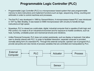
- 1. • Programmable Logic Controller (PLC) is a microprocessor based system that uses programmable memory to store instructions and implement functions such as logic, sequencing, timing, counting and arithmetic in order to control machines and processes. • The first PLC was developed in 1969 by General Motors. A microprocessor-based PLC was introduced in 1977 by Allen Bradley. It was based on 8080 microprocessor with circuitry to handle bit logic instructions at high speed. • Nowadays, PLC is viewed as a solid-state, digital, industrial computer that is capable of both logic and PID control. It is made to fit an industrial environment and for exposure to hostile conditions, such as heat, humidity, unreliable power and mechanical shocks and vibrations. • Unlike Personal Computer, PLC does not contain peripherals, such as display or keyboard, that allow user to directly interact with PLC. In order to facilitate interaction, separate computer is provided, normally taking form of a standard PC. Through this external computer, operator can re-program PLC, provide set-points and view trends of process variables that are controlled and manipulated by PLC. Programmable Logic Controller (PLC) PLC Actuator Process Sensor External Computer
- 2. • PLC consists of the following components: • Microprocessor – This is the brain of PLC. It reads input signals, executes control program and communicates results (decisions) of control program as action signals to the outputs. • Memory – It stores control program that is to be executed at a prescribed rate. • Power Supply – This component is used to convert the mains AC voltage to the low DC voltage (e.g. from 240V AC to 5V DC). This unit powers the processor and the circuits in the input and output modules. • Input Module – This component receives information from external devices (sensors). It contains circuitry that provides electrical isolation and signal conditioning functionalities. Input module can be analogue input (AI) or discrete input (DI) module. AI module receives continuously changing signal whose amplitude is proportional to the current value of the measured process variable. DI module receives discrete/digital (ON/OFF) information from discrete sensors, for example push button (ON if button is pressed, OFF if button is not pressed). Note that DI is much more frequently used than AI. • Output Module – This module communicates control actions to external devices (actuators). It contains circuitry required to interface PLC with actuators (e.g. digital-to-analogue converter and power amplifier). Like input module, output module can be analogue output (AO) or discrete output (DO) module depending on the type of actuator used. • Communication Module – This component allows PLC to communicate with external devices using sophisticated multiple-bit digital communication protocols (e.g. Ethernet). Programmable Logic Controller Architecture
- 3. Power Supply Communication Module Microprocessor + Memory Analogue Input (AI) Module Discrete Output (DO) Module Discrete Input (DI) Module Analogue Output (AO) Module Analogue Sensor Discrete Sensor Analogue Actuator Discrete Actuator Operator Workstation Programmable Logic Controller Architecture PLC
- 4. Communication Module Microprocessor Input Module External Computer Programmable Logic Controller Architecture PLC Output Module Actuator Process Sensor
- 5. Programmable Logic Controller (PLC)
- 6. • Distributed Control System (DCS) refers to control system architecture in which control elements are not centrally located but are rather distributed across manufacturing process. More specifically, control functions are performed by a number (tens, hundreds, thousands) of distributed microprocessor-based units (controllers) situated near to the devices being controlled or the instruments from which data is being gathered. • First DCS systems appeared around 1975. These were TDC 2000 (from Honeywell) and CENTUM (from Yokogawa). Their development was largely due to the increased availability of microcomputers and proliferation of microprocessors in process control. • DCS normally consists of the following units: • Input/Output Modules (interface between sensors/actuators and controllers) • Controllers (perform control functions such as PID algorithm, logic control or sequential control) • Operator Workstations (PC-like computers that allow users to interact with DCS controllers) • Database (collects and stores all the data related to DCS operations history) • Communication Network (allows all of the above elements of the DCS to communicate information between each other) Distributed Control Systems (DCS)
- 7. Operator Workstation 1 Operator Workstation 2 Operator Workstation 3 Controller 1 Controller 2 Controller 3 Controller 4 Sensor 1 Actuator 1 Actuator 2 Sensor 3 Actuator 3 Sensor 4 Actuator 4 Database Distributed Control System Architecture Input Module Output Module Sensor 2 Input Module Input Module Input Module Output Module Output Module Output Module
- 8. • HMI is the system that presents process data to the operator and through which the human operator controls the process. • It allows the user (operator/engineer) to interact (“talk/listen”) with the controlled process. • HMI is a software package that is normally installed on the Operator Workstation. • DCS vendors provide their own HMI software. Also, PLC vendors sometimes provide their own HMI software that can interact with PLC. • There are HMI software providers that are not associated with any particular PLC or DCS product but instead provide generic system that can interact with various DCS and PLC products through generic “open” interfaces. • Main functionality of HMI system: • Recording and trending of measured process variables. This allows the operator to view time- domain trajectories of recorded process variables. • Configuration of controller parameters. This allows the operator to modify controller parameters and then communicate them down to the actual process controller. • Display mimic of the actual process. This allows the operator to see in real-time a schematic representation of the plant being controlled. Human Machine Interface (HMI)
- 9. Human Machine Interface System Example Screen view of the HMI that interacts with the control system of the penicillin production vessel. Note that in the centre of this display is the mimic diagram of the controlled process. Also in the right section of this display are two trends of a measured process variable.
- 10. • SCADA system performs the following tasks • Collection of data from field devices, which can be sensors, actuators and controllers. • Transfer of field devices’ information via communication link to the central site (master station) • Execution of any necessary analysis and supervisory control calculations, all of which are taking place at the master stations. • Display process information on a number of operator screens. • Convey any required supervisory control actions back to the field devices. Supervisory Control and Data Acquisition (SCADA)
- 11. • In the past SCADA and DCS were generally thought of as separate entities. However, in recent years these two technologies have converged to a great extent. From a big-picture perspective, SCADA and DCS have become more or less synonymous with each other. However, there are some crucial differences between DCS and SCADA: • DCS is process oriented. Its primary role is to control a given process. By-product of DCS activity is to present data to process operators. SCADA is data-gathering oriented. Its primary function is to provide, analyse and record/display process information to operators. SCADA does not generally execute closed-loop control. • SCADA is designed to operate over large physical distances and is therefore capable of maintaining safe operation even when communication between operator workstation and field devices breaks down. This is not necessarily true for DCS systems which require at least one operator workstation to be functioning properly in order for controllers to maintain satisfactory process control. • Operator workstation within DCS is intimately linked to field devices (actuators, sensors and controllers) over short distances. On the other hand, operator workstation within SCADA may be connected to field devices over long-distance communication link. SCADA Versus DCS
- 12. • Critical prerequisite for the realisation of a control system is the establishment of communication between the components of the control loop: • Controller • Actuator • Sensor • In order to implement control system it is necessary to interface sensor with a controller so that measurements of controlled variable can be communicated from a sensor to a controller. Also, it is necessary to interface controller to an actuator so that control actions (values of manipulated variable) can be communicated from controller to an actuator. • Simplest form of communication between sensor and controller or actuator and controller consists of transmitting signal whose amplitude is either: • Proportional to the value of measured process variable or manipulated variable. This is the so- called analogue communication. • Dependent on a status of measured process variable or manipulated variable. For example, signal amplitude is HIGH if a storage tank is full, or it is LOW if a storage tank is not full. This is the so- called single-bit digital communication. • These two types of communication are very simple but the information content that is communicated is very limited (only the value of a variable is communicated). For example, it is not possible to communicate status of sensor/actuator using these simple communication types. Communication in Industrial Control
- 13. • In recent years, sensors and actuators have started to be equipped with microprocessors, which allow them to communicate with controllers or operator workstations using sophisticated communication protocols (e.g. Foundation Fieldbus, Industrial Ethernet). • These protocols allow sensors, actuators, controllers and operator workstations to exchange large amounts of data that include: • Values of process variables (values of controlled variables, manipulated variables, set-points) • Device status (normal, busy, faulty) • Configuration parameters of devices (sensor resolution, PID controller gains) • Messages exchanged using these sophisticated digital communication protocols consist of multiple bits and are therefore referred to as multiple-bit digital communication messages. • Communication protocols are analogous to human languages and represent rules of communication between different devices. Protocols specify length of a message and format of a message. They also specify which device is in control of communication (i.e. which device has a right to initiate communication). Communication in Industrial Control
- 14. Example of message format used in industrial control application for communication between operator workstation and PLC. Communication in Industrial Control 1. Hello 2. I am Operator Workstation A1 3. I want to talk to PLC1 4. I want you to change set-point to 3 5. I requested change of set-point from PLC1 6. Good Bye This segment signals beginning of the message This segment signals end of the message This segment provides address of a message sender This segment provides address of a message receiver This is the actual request made by the sending device This segment is used by the receiving device to check if any corruption of message has occurred during transmission. Request Message 1. Hello 2. I am PLC1 3. I want to talk to Operator Workstation A1 4. I changed set-point to 3 5. New set-point is equal to 3 6. Good Bye Response Message This is the actual response made by the sending device
- 15. • Master-Slave has been predominant type of communication in industrial control. • One device, called MASTER, initiates all of the communication. Master device is typically operator workstation and sometimes process controller such as PLC. • Other devices on the network are called SLAVES. They do not initiate communication. Instead, slaves listen for the requests made by the master device and then send their response messages. Slave devices are typically controllers as well as “smart” sensors and actuators (sensors and actuators with their own microprocessor that enables them to communicate using multiple-bit digital communication protocols). • Master station periodically makes request to each slave on a network: Master-Slave Communication 1. Operator Workstation -> PLC1: Change set-point to the value of 3.2 2. PLC1 -> Operator Workstation: I have changed set-point to the value of 3.2 3. Operator Workstation -> PLC2: Change set-point to the value of 6.7 4. PLC2 -> Operator Workstation: I have changed set-point to the value of 6.7 5. Operator Workstation -> PLC3: Change set-point to the value of -1.2 6. PLC3 -> Operator Workstation: I have changed set-point to the value of -1.2 PLC3 (SLAVE) PLC2 (SLAVE) PLC1 (SLAVE) Operator Workstation (MASTER)
- 16. • Advantages: • Communication failure between master and any of the slaves is detected fairly quickly. This is because master regularly requests information from each slave. • Collisions (two devices “talk” at the same time) CANNOT occur. Therefore the data throughput is predictable and constant, which is a critical requirement in real-time control applications. • Disadvantages • Variations in the data requirements of each slave cannot be handled. In other words, each slave is required to use the same response format even though some slave devices may be much more sophisticated than others. • Emergency requests from a slave, requesting urgent master’s action, cannot be handled. • Slaves needing to communicate with each other have to do so through the master. This leads to added complexity when designing master. • Due to the predictable data throughput, this communication method is referred to as deterministic communication method. This fact is the predominant factor for prevalence of master-slave protocols in control applications. This is particularly true for the low-level regulatory control (controller-sensor and controller-actuator communication) where the sampling rates are much higher than in supervisory control applications (MPC controller-PID controller communication link). Master-Slave Communication
- 17. • In the case of peer-to-peer communication, all devices on a network are allowed to initiate communication (i.e. make a request). They are all equal in their rights to make requests, hence the name peer-to-peer. Ethernet is an example of peer-to-peer communication protocol. • Due to the fact that any device can start sending message at any point in time it is highly possible that the so-called collisions will occur. Collisions occur when two devices start transmitting their messages simultaneously. • Management of these collisions is an important issue in peer-to-peer communication. • Typically used collision management scheme is the so-called Carrier Sense Multiple Access with Collision Detection (CSMA/CD). This scheme is used in the Ethernet protocol for example. Description of this scheme is as follows: • All devices on a network “listen” to the common communication link in order to detect if some other device is transmitting its message. • If there is no communication going on at the moment then a device starts transmitting its message. • If by accident two or more devices start transmitting their messages simultaneously, they then detect that the collision has occurred and each of them stops transmitting their messages. • Each of the devices involved in collision waits for a short and random time before re-transmitting its message. Peer-To-Peer Communication
- 18. • Advantages: • Device does not have to repetitively report its status, which may not have changed over the significant amount of time. Device sends a message only when some consequential event has occurred. This minimises communication traffic. • Emergency requests, made by any device over the communication link, can be processed. • Any two devices connected to the same network can communicate with each other without a need for a mediator. • Disadvantages • Communication link failure cannot be quickly detected because regular requests to each device are not made in peer-to-peer communication. • Collisions (two devices start “talking” at the same time) CAN occur. Therefore data throughput cannot be predicted which can be a serious limitation in real-time control applications. • Due to the unpredictability of data throughput, this communication method is referred to as probabilistic communication method. This fact was until recently the predominant factor in choosing not to employ peer-to-peer communication in real-time control applications. However, data transmission speeds of these communication networks are continuously increasing and have allowed protocols such as Industrial Ethernet to be employed in process control applications. Peer-To-Peer Communication
- 19. Communication in Industrial Control: Example Office Computer Programmable Logic Controller Actuator Sensor Operator Workstation Database Actuator and sensor are directly linked to PLC. Communication between actuator, sensor and PLC can be analogue , single-bit digital or multiple-bit digital communication. This depends on the sophistication of sensor and actuator. If actuator and sensor contain their own microprocessors (“smart” actuator and “smart” sensor) then multiple-bit communication is possible. In the case of multiple-bit digital communication it is most likely that master-slave communication protocol would be used rather than peer-to-peer with sensor and actuator being slaves while PLC is a master.
- 20. Communication in Industrial Control: Example Office Computer Programmable Logic Controller Actuator Sensor Operator Workstation Database Operator Workstation and PLC communicate with each other using multiple-bit communication protocol. Communication between these two devices can be accomplished by either master-slave or peer-to-peer digital communication protocol. If master-slave protocol is used then operator workstation would act as a master while PLC would act as a slave. Operator Workstation would request values of controlled and manipulated variables from PLC as well as providing PLC with set-point changes and PLC’s control algorithm changes. PLC may also provide information regarding operational status of sensor, actuator and itself (idle, busy, faulty). Operator workstation will contain HMI software package, standard computer screen, mouse and keyboard. These would then allow the operator to view trends of process variables and to modify control system parameters. Also, software package containing advanced process control (e.g. MPC) would be installed on the operator workstation providing set-points to PLC.
- 21. Communication in Industrial Control: Example Office Computer Programmable Logic Controller Actuator Sensor Operator Workstation Database Operator Workstation and database would most probably communicate using peer-to-peer communication protocol. The purpose of this communication link is to store current information regarding controlled process into a database. Information regarding controlled process is provided by operator workstation, which in turn has obtained this information from PLC.
- 22. Communication in Industrial Control: Example Office Computer Programmable Logic Controller Actuator Sensor Operator Workstation Database Database and office computer would communicate using peer-to-peer communication protocol (e.g. Ethernet). The purpose of this communication link is to provide current or historical information regarding controlled process to office computer. Office computer may then perform analysis of this data to establish control system performance. Also, office computer may provide display or trend of controlled and manipulated process variable or some other key performance indicator variable, which was derived from measured process variables. Office computer is generally disabled from writing values into database. This ensures security of control system. This means that supervisory controller would NOT be implemented on office computer since it is disabled from interacting with operator workstation and, therefore, with PLC.
- 23. • One of the current trends in industrial control implementation is to design the overall control system using components provided by different companies. For example, manufacturing facility would purchase DCS from company AAA, 3 PLCs from company BBB, 1 PLC from company CCC, HMI software from company DDD and MPC control software from company EEE. • The task of interfacing these components so that they function as a whole is the so-called system integration. • Because each of these components or sub-systems performs different functions and manipulates information using different formats, it is necessary for a system integrator to understand input/output specification of each of them and to know the methods by means of which output or input of one sub- system can be connected to input or output of another sub-system. • Note that system integrators are generally not involved in designing and tuning of the control loops and associated control algorithms. System Integration Source : University of Manchester, UK 2009