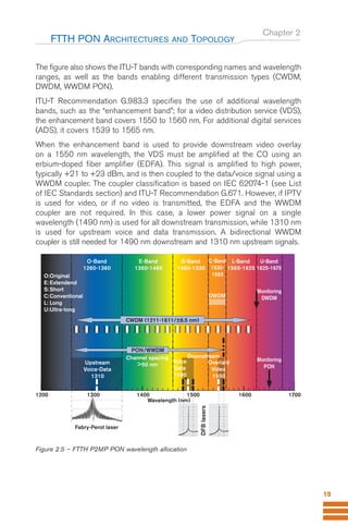
Fiber-optic telecommunications began generating interest in the late 1970s, but major breakthroughs like the optical amplifier and narrowband filter, which enabled wavelength-division multiplexing (WDM), significantly advanced the field in the mid-1990s. This led to an era of rapid bandwidth demand growth and service providers extending optical fiber networks closer to premises. New technologies like fiber-to-the-x (FTTx) and PONs have emerged as a result.
A detailed review of PON system performances, issues and testing solutions


![Chapter 1
1.3 Historical Development of FTTH
In the mid 90s, a group of international network service providers
gathered to develop standards documents that would eventually define the new
fiber-to-the-home passive optical network. It would allow them to offer
cost-effective connections to subscribers, open a new market, and help
incumbent service providers to better compete in their market by developing
standardized equipment. The group created the full-service access network
(FSAN)5
. Furthermore, the US legislature signed the Telecommunications Act
of 1996 to “promote and reduce regulation in order to secure lower prices
and higher-quality services for American telecommunications consumers and
encourage the rapid deployment of new telecommunications technology.”
This policy as been followed by many other countries around the world.
The International Telecommunication Union’s telecommunications standardization
sector (ITU-T)6
turned FSAN specifications into recommendations. The FSAN
specification for asynchronous transfer mode (ATM)7
-based PONs became ITU-T
Recommendation G.983.1 in 1998 [see PON-related ITU-T recommendations
in Bibliography].
In 2001, the FTTH Council was formed to promote FTTH in North America
and to advise the US legislature. This resulted in the Broadband Internet
Access Act of 2001, which provides tax incentives to companies that invest in
next-generation broadband equipment. The term broadband denotes an access
bandwidth to the user comparable to xDSL and above; i.e., a few Mb/s and
higher. It is expected that the capacity required by new applications may
increase to 1 Gb/s by 2015.
INTRODUCTION
11
5
www.fsanweb.org
6
www.itu.int
7
ATM is a network technology based on transferring data in cells of a fixed size.
ONT
Store
Store
Circuit
switch
Residential area
Small
businesses
Office building
Apartment
building
Office park
Central office
OLT
Drop
Splitter
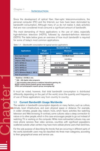
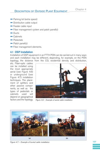
Figure 1.10 – Example of FTTH PON in new housing (Greenfield) development
Guide FTTH-p1-68:Layout 1 09/06/10 09:13 Page 11](https://image.slidesharecdn.com/exfobookfttx-pon-technology-testingen-230528183113-ac616da2/85/exfo_book_fttx-pon-technology-testing_en-pdf-19-320.jpg)

![Chapter 1
As a result of all these recent developments, interest in FTTH has spurred
exponentially:
SOHOs are demanding more bandwidth and more services.
FTTH PON offers the high-bandwidth capability of optical fibers and a wide
diversity of services (data, voice, and video) at a low cost because a number
of end users can share bandwidth on a single fiber, and because all
outside plant equipment is passive.
New standards such as those established by the ITU-T and the Institute of
Electronic and Electrical Engineers (IEEE)8
have greatly increased the
design commonality, capacity, survivability, security and versatility of PONs,
opening the opportunity for mass economy of scale and tremendously
lower costs that were not conceivable before.
FTTH PON can now be offered by many different types of carriers:
Incumbent local exchange carriers (ILECs) and RBOCs
Rural local exchange carriers (RLECs)
CLECs
Utility companies
Municipalities, etc.
FTTH PONs are increasingly installed in new housing (Greenfield)
developments (see Figure 1.10)
In addition, many countries in Asia (China, Japan, Korea, Singapore and
Taiwan) and Europe are presently testing or deploying PONs, and the
IEEE-802.3ah [see IEEE access network standards in Bibliography] task force9
has currently drafted standards an for Ethernet-based PON (EPON). From a
worldwide market perspective, PON revenues surged 240% from 2002 to
2003 to US$ 182 million.
Table 1.5 describes a number of available services typically supported by FTTH
PONs. Voice communication over the PON can be provided using conventional
switched circuits or voice-over-Internet protocol (VoIP). Similarly, video can be
provided using radio-frequency (RF) cable-TV broadcast standards or IPTV
(digital TV transmitted using the Internet protocol; the expression video-over-IP
is also used).
INTRODUCTION
13
8
www.ieee.org
9
grouper.ieee.org/groups/802/3/efm
Guide FTTH-p1-68:Layout 1 09/06/10 09:13 Page 13](https://image.slidesharecdn.com/exfobookfttx-pon-technology-testingen-230528183113-ac616da2/85/exfo_book_fttx-pon-technology-testing_en-pdf-21-320.jpg)


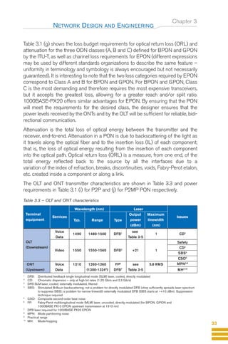
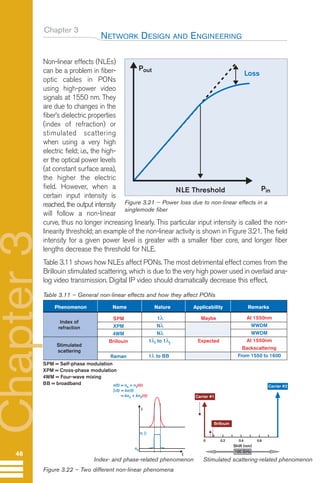
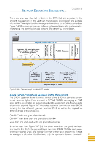
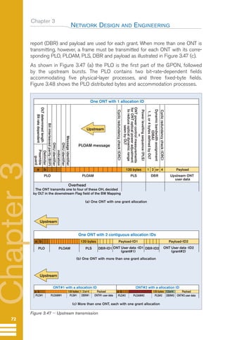
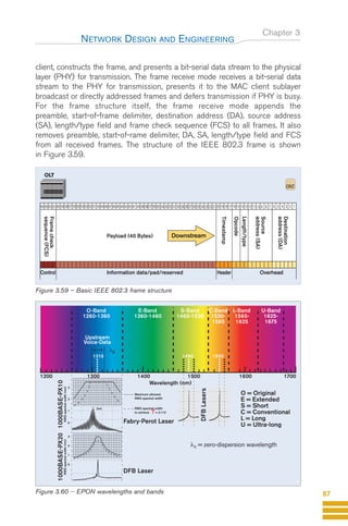
![Chapter 3
This chapter examines the detailed architecture used in FTTH PONs; namely,
the design and engineering of a PON, including a detailed description of the
various components and protocols used.
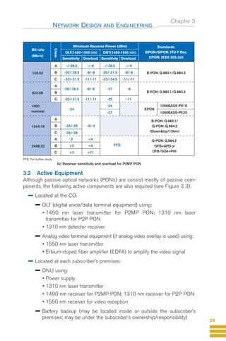
3.1 PON Technology
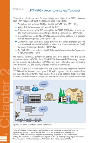
At the CO, the public switched telephone network (PSTN) and Internet services
are interfaced with the optical distribution network (ODN) via the OLT. In a P2MP
PON, the downstream 1490 nm wavelength and upstream 1310 nm wavelength
are used to transmit data and voice. The downstream 1550 nm wavelength can
be used for analog video overlay. Multiple ONTs are connected to each PON
through one or more splitters. In a P2P system, the voice and data are transmitted
on the same 1310 nm wavelength downstream and upstream because it uses a
fiber pair; one fiber downstream and another one upstream. For analog overlay
video, 1550 nm is still used in the same configuration as for P2MP.
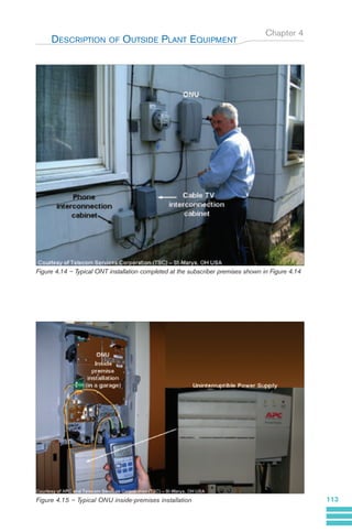
Figure 3.1 shows a detailed view of the main components of a PON, and
Figure 3.2 shows an example of the physical-layer P2MP FTTH PON topology.
NETWORK DESIGN AND ENGINEERING
22
Chapter
3
EDFA
1310 nm Rx
Service
interface
1550 nm Tx
Voice/Data
Video
1550 nm Rx
Video
OLT
Central office
Premise
ONT
1310 nm Tx
WWDM
coupler
Fiber
management
system
Fiber
management
system
Service
interface
1310 nm Tx
Voice/Data
1310 nm Rx
WWDM
Coupler
Fiber pair
EDFA
Service
interface
1550 nm Tx
Voice/Data
Video
1490 nm Tx
WWDM
coupler
OLT
ONT
Fiber management
system
Central office
Premise
Single fiber
1550 nm Rx
Video
1310 nm Tx
Voice/Data
1490 nm Rx
Service
interface
WWDM
coupler
Splitter
Fiber distribution
hub
Drop
(a) P2P
(b) P2MP PON
1310 nm Rx
WWDM
coupler
WWDM
coupler
Figure 3.1 – Main PON components – basic system architecture [Pv1_37]
Guide FTTH-p1-68:Layout 1 09/06/10 09:13 Page 22](https://image.slidesharecdn.com/exfobookfttx-pon-technology-testingen-230528183113-ac616da2/85/exfo_book_fttx-pon-technology-testing_en-pdf-30-320.jpg)


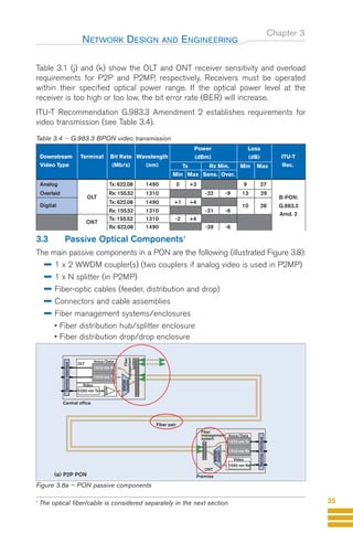


![Chapter 3
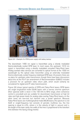
Table 3.8 illustrates the critical issues of PON passive components.
Table 3.8 – Major optical issues for passive components [Pv1_54]
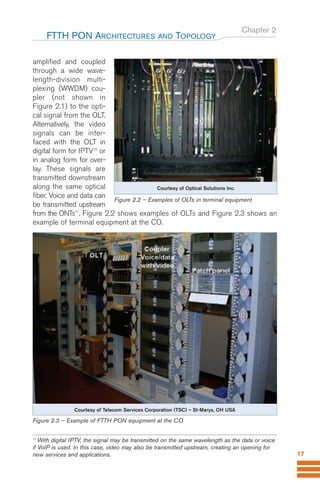
3.3.3 Connectors
Because of the high-power analog video signal that PONs will carry, the APC
connector was chosen. The APC connector is an angled (8o
) connector
(as shown in Figure 3.15) and as such provides very low reflection (ORL) of
65 dB or better.
Small-form-factor connectors as shown in Figure 3.16 are preferable for PONs.
NETWORK DESIGN AND ENGINEERING
42
Chapter
3
IL: insertion loss
RL: return loss
PDL: polarization dependent loss
APC: angled physical contact/angled polished connector
* +21 to +23 dBm at 1550 nm at Video EDFA output
Issues Coupler Splitter Connectors Closures
IL (bidirectional) very high 1x32
RL (bidirectional) APC
Others
PDL
Group delay +
1310 nm FP laser/high bit rate
ripple
High optical
1550 nm 1550 nm close to CO close to CO
power*
Cleanliness if connectorized
Environment in closure ONT
Negligible
Critical for specified case
Very critical
N/A
Endface
~8º
Ferrule Ferrule Ferrule Ferrule
PC Connector
Reflection
Input
Fiber Fiber Fiber Fiber
APC Connector
Figure 3 15 – Difference between PC and APC connectors
Guide FTTH-p1-68:Layout 1 09/06/10 09:13 Page 42](https://image.slidesharecdn.com/exfobookfttx-pon-technology-testingen-230528183113-ac616da2/85/exfo_book_fttx-pon-technology-testing_en-pdf-50-320.jpg)


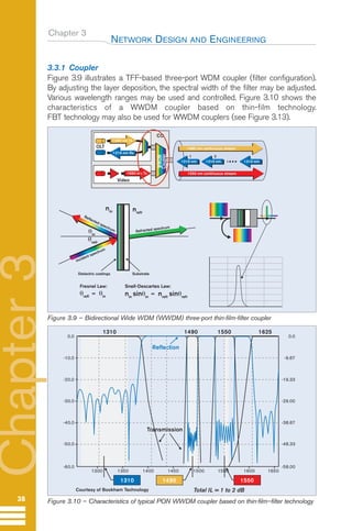
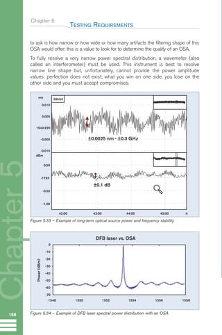
![Chapter 5
For PON testing, the OTDR should be able to test at three wavelengths (1310, 1490
and 1550 nm) and possibly a fourth one (1625 or 1650 nm for macrobending-
sensitive detection). In many cases, however, testing at 1550 nm is considered
adequate to cover the 1490-nm region at the same time. It is generally agreed
that the fiber attenuation at 1490 nm is approximately 0.02 dB greater than at
1550 nm (see Figure 3 10 on page 30). This is usually true for very recent
vintage fiber (late ’90s and more recent), especially for the G.652.C
low-water-peak fiber. However, this may be questionable for older vintage fiber
(early ’90s and older) when G.652.C did not yet exist and when little interest
was placed on the water peak (1383 nm peak in the E-band). In many cases,
the amplitude and the width of the water peak were much larger than what is
currently available. Another reason to test both at 1490 nm and 1550 nm is
based on the fact that each wavelength carries different critical types of service.
A new type of PON-optimized OTDR uses the 1650 nm wavelength for in-service
troubleshooting of PONs. This type of OTDR has a dedicated port for testing at
1650 nm and uses a filter to reject all unwanted signals (1310 nm, 1490 nm
and 1550 nm) that could contaminate the OTDR measurement. Only the OTDR
signal at 1650 nm is allowed to pass through the filter, generating a precise
OTDR measurement. This type of OTDR does not interfere with the CO’s transmitter
lasers, because the 1650 nm wavelength complies with the ITU-T Recommendation
L.41 (Maintenance wavelength on fibers carrying signals). This recommendation
suggests a 100 nm difference between the OTDR wavelength used for in-service
TESTING REQUIREMENTS
129
Conventional OTDR
4
2
20.00
30.00
40.00
50.00
60.00
A
2
6 8 km
Blind after the splitter
PON-optimized OTDR
4
2
40.00-
35.00-
30.00-
25.00-
20.00-
15.00-
10.00-
5.00-
0.00- A
2
3
6 8 10 km
B
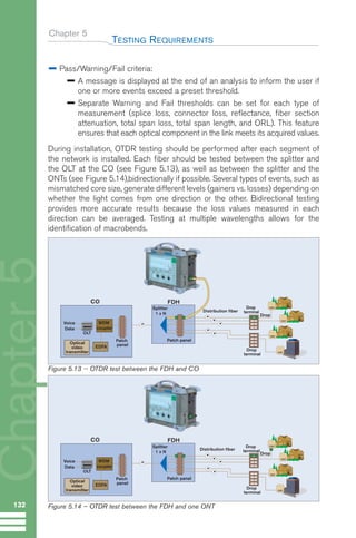
Figure 5.12 – Results from a conventional and a PON-optimized OTDR [P147 from “Testing
and Maintaining FTTH PONs: New Challenges” - Stéphane Chabot]
GuideFTTH-p69-144:Layout 1 09/06/10 09:40 Page 129](https://image.slidesharecdn.com/exfobookfttx-pon-technology-testingen-230528183113-ac616da2/85/exfo_book_fttx-pon-technology-testing_en-pdf-137-320.jpg)


![LFD with interchangeable adapter heads – has the following characteristics:
• Detects traffic
• Measures signal strength anywhere on along fiber without having to
disconnect them
The interchangeable adapter heads allows for testing of different fiber types.
Table 5.7 to Table 5.9 present typical troubleshooting procedures for different
situations. See also [2].
5.2 Protocol Layer
5.2.1 ATM Service Activation and Provisioning
One of the advantages of using ATM in PONs is that ATM includes
management features to guarantee quality of service (QoS). This allows
network service providers (NSPs) to guarantee error free transmissions to
their customers.
An ATM service is often governed by the terms of a service-level agreement
(SLA). Both NSPs and content providers are interested in knowing how well the
service will conform to the SLA.
An SLA is a legal contract between a service provider and a customer that
specifies a required level of service. Respecting SLAs can be a way for service
providers to attract and retain customers, while sub-standard service can be
synonymous with various penalties such as:
Poor customer satisfaction
Increased spending on maintenance
Often, direct financial penalties
SLAs typically specify:
Maximum downtime
Mean time to repair (MTTR) when outages occur
Minimum performance criteria
Two types of QoS testing can be performed on ATM-based PONs similar to
other network types:
Non-intrusive testing (in-service) used to monitor live traffic for service-
affecting faults
Intrusive testing (out-of-service) used for circuit turn-up and troubleshooting
faults
The ATM-based PON service provider must verify the QoS of ATM connections
to verify that the PON is delivering the QoS that customers are expecting.
An end-to-end QoS test can be run in order to determine if performance
will degrade over time. If so, the NSP will take necessary corrective actions,
including equipment upgrades, to improve service.
Chapter 5
TESTING REQUIREMENTS
139
GuideFTTH-p69-144:Layout 1 09/06/10 09:40 Page 139](https://image.slidesharecdn.com/exfobookfttx-pon-technology-testingen-230528183113-ac616da2/85/exfo_book_fttx-pon-technology-testing_en-pdf-147-320.jpg)


![Chapter 5
providers to establish service-level agreements (SLAs) with their customers.
Unfortunately, Ethernet was not designed with QoS in mind and, originally,
offered no means to differentiate between low- and high-priority data.
This made it difficult to combine different types of services, such as email and
voice communications, over the same link while ensuring that transfer rates
met pre-established criteria. Various solutions have been proposed to overcome
this shortcoming.
One improvement is to manage network traffic by grouping similar types of traffic
together (for example, e-mail, streaming video, voice, large document file transfer)
and treating each type as a class with its own level of service priority.
This technique is called class of service (CoS). CoS is a queuing discipline,
whereas QoS uses a wider range of techniques to manage bandwidth and
network resources. CoS examines packet parameters or CoS markings in order
to classify packets and place them in queues of different priorities (see Figure
3.67). Unlike QoS traffic management, CoS technologies do not guarantee a
level of service in terms of bandwidth and delivery time; they offer a "best-
effort" for each class. On the other hand, CoS technologies are simpler to man-
age and more scalable in terms of network growth, structure and traffic volume.
The three main CoS technologies are:
802.1p Layer 2 tagging
Type of service (ToS)
Differentiated services (DiffServ)
The first two make use of three bits in the Layer 2 packet header that can be used
to specify eight levels of priority. DiffServ, on the other hand, uses more complex
policies to determine how to forward a given network packet and offers 64 possible
forwarding behaviors, known as per-hop behaviors (PHBs).
Regardless of the CoS specified for any particular type of data, various factors
such as network congestion can affect the actual rate at which the data is
transferred. For this reason, specific tests are required to verify Ethernet
performance in order to ensure that the SLA requirements are met.
5.2.2.2 Ethernet Performance Verification
The data-communication industry has put together a test methodology to
address the issues of performance verification at the Layer 2 and Layer 3. The
Internet Engineering Task Force (IETF) has developed RFC 2544 [3] in order
to specify the requirements and procedures for testing the following perform-
ance characteristics:
Performance availability (throughput)
Transmission delay (latency)
Link burstability (back-to-back frames)
Service integrity (frame loss)
TESTING REQUIREMENTS
145
Guide FTTH--p145-190.qxd:Layout 1 09/06/10 09:55 Page 145](https://image.slidesharecdn.com/exfobookfttx-pon-technology-testingen-230528183113-ac616da2/85/exfo_book_fttx-pon-technology-testing_en-pdf-153-320.jpg)

![Chapter 5
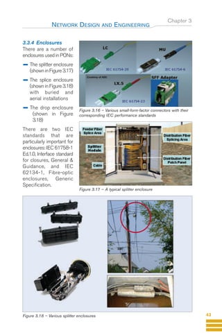
5.2.2.4 Throughput
Throughput is the maximum rate at which none of the offered frames are
dropped by the network under test (NUT). For example, the throughput test
(Figure 5.21) can be used to measure the rate-limiting capability. The through-
put is equivalent to the bandwidth.
The throughput test allows vendors to report a single value, which has proven
to be useful in the marketplace. Since even the loss of one frame in a data
stream can cause significant delays while waiting for the higher-level protocols to
time out, it is useful to know the actual maximum data rate that the device can
support. Measurements should be taken over an assortment of frame sizes.
Separate measurements should be taken for routed and bridged data in those
devices that can support both. If there is a checksum in the received frame, full
checksum processing must be done.
The following are issues that will affect throughput test results:
Single path vs. aggregate
Load
Unidirectional vs. bidirectional testing
Checksum processing required on some protocols
Packet size
Throughput test procedure :
Send a specific number of frames at a specific rate through the NUT and
then count the frames that are transmitted by the NUT.
If the count of offered frames is equal to the count of received frames,
the rate of the offered stream is raised and the test rerun.
If fewer frames are received than were transmitted, the rate of the offered
stream is reduced and the test is rerun.
TESTING REQUIREMENTS
147
Figure 5.21 – Measuring throughput
Loop-Back
ONT
(a) Test with one instrument
Dual test set
ONT
(b) Test with two instruments
1
All test procedures are from RFC 2544 [3].
Guide FTTH--p145-190.qxd:Layout 1 09/06/10 09:55 Page 147](https://image.slidesharecdn.com/exfobookfttx-pon-technology-testingen-230528183113-ac616da2/85/exfo_book_fttx-pon-technology-testing_en-pdf-155-320.jpg)


![Chapter 9
GR-1081, Generic Requirements for Field-Mountable Optical Fiber Connectors
GR-1209, Generic Requirements for Fiber-Optic Branching Components
GR-1221 Generic Reliability Assurance Requirements for Fiber-Optic
Branching Components
GR-2898, Generic Requirements for Fiber Demarcation Boxes
GR-3120, Generic Requirements for Hardened Fiber-Optic Connectors,
including field-mateable and OSP hardened connectors
GR-3121 - Generic Requirements for Below-Ground Cabinets, intended
to house passive fiber-optic network components that could be located in a
service provider right-of-way or on a customer premises, such as an apartment
complex, and can serve as a distribution hub for FTTP services
GR-3122 - Generic Requirements for FITS (Factory Installed Termination
System), factory preassembled.
GR-3123 - Generic Requirements for Indoor Fiber Distribution Hubs, housing
passive fiber-optic network components and located on a customer premise,
such as an apartment complex; and serve as a distribution hub for FTTP services.
TR-NWT-000937, Generic Requirements for Building Entrance Terminals
9.5 Other References
[1] “Optical Network Hardware and PON Hardware”, Infonetics Research,
Quaterly worldwide market share and forecast services; and Fiber Optics Online
(www.fiberopticsonline.com) “PON Surges 240% in CY03; Optical Hardware
Up 16% in 4Q03” 27 Feb. 2004.
[2] Girard, A., and Masson, B., “FTTx PON Guide, Testing Passive Optical
Networks” 2nd Ed., EXFO Electro-Engineering Inc., Quebec City, Canada, 60pp,
2004
[3] Girard A., Measuring Fiber Characteristics, Encyclopedia of Modern Optics,
Ed. Robert D. Guenther, Duncan G. Steel and Leopold Bayvel, Elsevier, Oxford,
pp. 449-467, 2004. ISBN 0-12-227600-0 (www.elsevierphysics.com/emo)
[4] RFC 2544 “Benchmarking Methodology for Network-Interconnect
Devices”, Internet Engineering Task Force (IETF) Ed. S. Bradner & J. McQuaid,
Copyright (C) The Internet Society, March 1999
(www.faqs.org/rfcs/rfc2544.html).
[5] “Ethernet Reference Guide”, EXFO Electro-Engineering Inc., Quebec
City, Canada, 2005
[6] Numerous useful application notes (go to www.exfo.com)
BIBLIOGRAPHY
190
Chapter
9
Guide FTTH--p145-190.qxd:Layout 1 09/06/10 09:55 Page 190](https://image.slidesharecdn.com/exfobookfttx-pon-technology-testingen-230528183113-ac616da2/85/exfo_book_fttx-pon-technology-testing_en-pdf-198-320.jpg)