1. Corning Cable Systems
Standard Recommended Procedure (SRP) 003-668
Issue 5, March 2005
Page 1 of 26
OptiTect™ Premiere Cabinet
FDH-HDF
p/n 003-668
Contents
Related Literature ...................................................................................................................2
Admonishments.......................................................................................................................2
1. General .............................................................................................................................................3
1.1 Use and Application ................................................................................................................3
1.2 Planning ..................................................................................................................................4
2. Materials and Tools Required ..........................................................................................................4
2.1 Materials ..................................................................................................................................4
2.2 Tools ........................................................................................................................................5
2.3 Auxiliary Equipment ...............................................................................................................5
3. Components and Shipping Container Contents .............................................................................5
2. Page 2 SRP 003-668 • Issue 5 • March 2005
OptiTect™ Premiere Cabinet — FDH-HDF
Revision History
Issue Date Reason for Change
5 03/2005 Added shelf restraint bar
4 09/2004 Added position for extra module and expanded connector storage
3 08/2004 Added cushion between skirt and concrete when pad-mounting
2 05/2004 Added vents/filters and pole-mount capability
1 04/2004 Initial Release
Related Literature
The following Corning Cable Systems’ literature may be helpful in ordering or installing this
product and accessories/optional products.
000-227 Instruction, Fiber Distribution Hub Ground Kit
000-228 Instruction, Hardware Mounting Kits — OptiTect Cabinets
000-229 Instruction, Pole-mounting Kits — OptiTect Cabinets
000-231 Instruction, Shim Leveler Kit — OptiTect Cabinets
000-233 Instruction, Filter Kit — OptiTect Cabinets
003-670 Instruction, OptiTect FDH Coupler Modules
003-677 Instruction, OptiTect Cabinets — Pad- and Pole-mounting Instructions
Admonishments
The precautionary terms used by Corning Cable Systems in its standard recommended
procedures conform to the guidelines expressed in the American National Standards Institute
document (ANSI Z235) for hazard alert messages. Alerts are included in this instruction based
on the following:
4. Storage and Transportation..............................................................................................................6
5. Unpackaging the Cabinet and Components....................................................................................7
6. Installing the Cabinet .......................................................................................................................8
6.1 Installation on a Pad................................................................................................................8
6.2 Installation on a Pole ............................................................................................................10
7. Grounding the Cabinet ..................................................................................................................12
8. Work Operations ............................................................................................................................13
9. Installing Coupler Modules............................................................................................................14
10. Connecting Feeder Cable to Coupler Input Fibers ......................................................................15
11. Routing Coupler Output Fibers to FDH Shelf .............................................................................17
11.1 Route Coupler Output Fibers to be Connected Now .........................................................17
11.2 Route and Store Coupler Output Fibers to be Connected Later........................................20
12. Optical Hygiene .............................................................................................................................21
13. Securing Cabinet ............................................................................................................................21
14. Testing.............................................................................................................................................22
14.1 Provisioning Tests .................................................................................................................22
14.2 Troubleshooting Tests...........................................................................................................22
15. Maintenance ...................................................................................................................................22
16. Growth ............................................................................................................................................24
Glossary .................................................................................................................................24
Customer Service and Information ......................................................................................25
3. SRP 003-668 • Issue 5 • March 2005 Page 3
OptiTect™ Premiere Cabinet — FDH-HDF
DANGER indicates an imminently hazardous situation which, if not
avoided, will result in death or serious injury.
WARNING indicates a potentially hazardous situation which, if not
avoided, could result in death or serious injury.
CAUTION indicates a hazardous situation which, if not avoided, may
result in minor or moderate injury.
1. GENERAL
The OptiTect™ Premiere Cabinet (FDH-HDF-series) functions as an interface between the
telecommunication provider’s network and individual customer connections. The cabinet
provides mechanical and environmental protection for the splices and connector interfaces while
allowing easy access for the service provider. The cabinet enables a management system for
optical fiber, connectors, and coupler modules and a test access point to verify the integrity of
the network.
The cabinet is capable of storing 432 distribution fibers, 26 feeder fibers, and 14 1x32 or 28 1x16
coupler modules and associated pigtail outputs. A maximum of 30 fusion splices can be stored in
the organizer in the splice drawer. Organizers for mechanical splices or specific organizers to
accommodate customer preferences can be requested when ordering the cabinet.
1.1 Use and Application
The OptiTect Premiere Cabinet may be used in an outdoor environment, either mounted on a
pad or a pole. The cabinet design allows front access to the fibers, connectors, and coupler
modules for management, testing, and maintenance by the craft persons. Safety rings are
installed at the top of the pole-mountable cabinets to enable installers to attach safety straps
during work operations.
The interior is accessible through two hinged front doors that are secured with a three-point
latch. The cabinet doors can be locked with a 216B tool. From one to three connectorized
distribution cables are preinstalled and attached to the internal housings. Feeder cable is also
preinstalled, strain-relieved, and either factory-spliced to the coupler input fiber or prepared for
splicing in the field to the coupler input fiber.
• Feeder cable is routed into the cabinet and into the splice drawer. After splicing the
feeder cable to the coupler module input fiber, the splices are stored in a splice organizer
inside the splice drawer.
• Pre-connectorized distribution cable(s) are routed into the cabinet and mated in the
connector adapter field of the individual shelves within each housing. Each adapter field
is ready to receive the connectorized output fibers from the coupler modules.
• Coupler modules (purchased separately) are installed into the coupler storage area.
Coupler modules are available in two versions—a 1x16 model, which contains one input
fiber and 16 output fibers, or a 1x32 model, which contains one input fiber and 32 output
fibers. The coupler storage area can hold up to 28 1x16 modules, 14 1x32 modules, or a
combination of the two sizes of modules. Preconnectorized output fibers from the
coupler modules can be connected at the time of installation in the high-density fiber
(HDF) shelves or routed to and stored in a connector storage field for connection later.
4. Page 4 SRP 003-668 • Issue 5 • March 2005
OptiTect™ Premiere Cabinet — FDH-HDF
1.2 Planning
Contact a Corning Cable Systems customer service representative to place an order for this
product in the configuration required by your network installation plan.
• The cabinet installed on the skirt is 32-inches wide, 19-inches deep, and 60-inches high.
Ensure that sufficient space is available at the installation site to accommodate the
cabinet. Allow 16 inches in front and 10 inches on each side of the cabinet to enable the
doors to open fully. No clearance is necessary behind the cabinet since there is no rear
access to the interior of the cabinet.
• The installing company should obtain rights-of-way from property owners and permits
or other approvals from public authorities prior to installation of the cabinet.
• Select an appropriate site per your design plan and follow standard local practices to
construct or purchase a concrete pad suitable for installation of the cabinet. The pad
should be able to withstand the weight of a fully loaded cabinet (approximately 350
pounds). A metal template (p/n FDH-MTNG-MTLTP) is offered that supplies cabinet
dimensions and recommended location of conduit, mounting hardware, and grounding
rod to assist with on-site or precast pad construction.
2. MATERIALS AND TOOLS REQUIRED
2.1 Materials
The following materials are required to install the OptiTect FDH-HDF cabinet onto a pad:
• Paper mounting template (provided)
• Shim kit (provided)
• Grounding kit (provided)
• Standard mounting hardware kit (p/n FDH-MTNG-KIT-TDST, provided), includes
bolts and washers for mounting on a pad with precast studs
NOTE: Mounting hardware for pads without precast studs may be purchased separately:
For mounting on a pad with threaded inserts, order p/n FDH-MTNG-KIT-TDIN
For mounting on a pad by inserting wedge anchor threaded studs, order p/n FDH-
MTNG-KIT-DRLAN
For wooden pole-mount installations, use the pole-mounting hardware kit (p/n FDH-POLE-
MNT-KIT, purchased separately), which supports poles ranging in diameter from 10 to 14
inches, and contains the following galvanized hardware:
• (2) 3
/4-10 x 16-inch carriage bolts • (2) 3
/4-ID x 2-inch square washers
• (2) 3
/4-inch split lock washers • (2) 1
/2 x 4-inch lag screws
• (2) 3
/4-10 square nuts
The following materials are required for installations of all pad- or pole-mounted OptiTect
FDH-HDF cabinets:
• Ground kit for cabinet (provided)
• Heatshrink splice protectors for fusion splicing (purchased separately) (p/n 2806032-01,
package of 50; 40 mm long)
• Lint-free wiping material
• Isopropyl alcohol
5. SRP 003-668 • Issue 5 • March 2005 Page 5
OptiTect™ Premiere Cabinet — FDH-HDF
2.2 Tools
To install the cabinet, the following tools may be required:
• Hoist or crane
• Forklift or handtruck
• 216B tool or a 7
/16-inch nutdriver or wrench (for entry into the interior of the cabinet)
• Fusion splicer
• Fiber cleaver
• Crescent wrench
• Drill with 7
/8- to 1-inch auger bit
• 9
/16-inch nut driver or socket
• 3
/4-inch nut driver or socket
• Tensioning tool (p/n UCN-KT-IT-TT, purchased separately) for pole-mounting using
bands
Additional tools may be required for maintenance or to expand the capacity of the cabinet:
• Phillips-head screwdriver
• Heat gun
2.3 Auxiliary Equipment
There is no auxiliary equipment required to install the cabinet. If the cabinet is not full to
capacity, additional products may be installed to expand the customer connections. Refer to the
section, Growth, for details on expanding the capacity. Contact a Corning Cable Systems
customer service representative to order additional products in the configuration required by
your network installation plan.
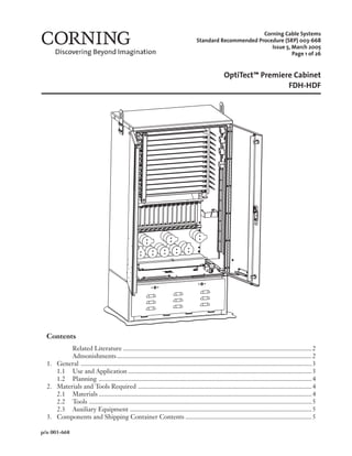
3. COMPONENTS AND SHIPPING CONTAINER CONTENTS
Figure 1 provides a pictorial description of the cabinet and its components.
Packing List of Shipping Container Contents
(1) OptiTect Premiere Cabinet, prestubbed with distribution and feeder cables in lengths
and quantities specified by the customer, with factory-installed coupler module(s), either
1x16 or 1x32, as specified by the customer
(1) Grounding kit (p/n FDH-GRND-KIT)
(1) Paper mounting template
Additional Container Contents for Pad-mounted Cabinets
(1) Standard pad-mounting hardware kit for use with pads with precast studs
(1) Shim kit
(1) Rubber mounting cushion
Additional Container Contents for Pole-mounted Cabinets
Pole-mounting kit containing:
(1) Pole-mount Bracket Assembly
(2) Angled mounting brackets
Galvanized hardware:
(2) 3
/8-inch lock washers (2) 3
/8-16 x 1.50-inch carriage bolts
(2) 3
/8-inch flat washers (2) 3
/8-16 hex-head nuts
NOTE: Hardware to secure the cabinet to the pole is not supplied and must be ordered separately
(p/n FDH-POLE-MNT-KIT)
6. Page 6 SRP 003-668 • Issue 5 • March 2005
OptiTect™ Premiere Cabinet — FDH-HDF
Figure 1 — Cabinet Components
Wide Deep High
32.00 19.00 60.00
DIMENSIONS (in inches)
Lifting Eyes
Retaining Guide
Coupler Output
Connector
Storage Field
Coupler
Output Fiber
Organizer
Latch
Coupler
Output Fiber
Transition Area
Door
Restraint
(Lift up gently
to disengage.)
Feeder
Cable
(not shown)
Splice Drawer
Access Panel
Coupler Output
Fiber Slack
Storage Hubs
Routing
Clips
Preconnectorized
Distribution
Cable (not shown)
Coupler Module
Storage Area
HDF Drawer
Shelf
Restraint
Bar
Ground Bar Vent
4. STORAGE AND TRANSPORTATION
The shipping container and its contents can be stored indoors in any typical warehouse or
central office environment, controlled or uncontrolled. A forklift or handtruck capable of lifting
approximately 450 pounds is required to unload or transport the product prior to unpackaging.
Observe all local safety precautions when moving the container. Do not double-stack shipping
containers.
7. SRP 003-668 • Issue 5 • March 2005 Page 7
OptiTect™ Premiere Cabinet — FDH-HDF
5. UNPACKAGING THE CABINET AND COMPONENTS
Step 1 Place the container near the site prepared for installation of the cabinet.
Step 2 Packaging consists of cardboard container:
If the package has a cardboard cover, loosen the 1x2-inch wooden framing at the
edge of the container. Lift the cardboard cover off to access the cabinet and
components (Figure 2).
Figure 2 — Remove Cardboard Packaging
Remove installation
instruction and paper
mounting template from
packaging.
OR Packaging consists of a plastic cover:
If the cabinet is encased in a plastic cover
held in place with metal bands, cut the
metal bands and slit the plastic cover
from top to bottom, allowing the plastic
to fall to the ground.
IMPORTANT: Do NOT remove the plastic
shrinkwrap that is securing the cables
at this time.
Step 3 If necessary, remove and reattach the
lifting eyes at the top of the cabinet so
that the obround slot is above the
cabinet.
Step 4 Remove and appropriately dispose of the
shipping materials.
Distribution Cable(s)
Feeder Cable(s)
Lifting Eye
Figure 3 — Remove Plastic Covering
8. Page 8 SRP 003-668 • Issue 5 • March 2005
OptiTect™ Premiere Cabinet — FDH-HDF
FEEDER
FEEDER
DISTRIBUTION
DISTRIBUTION
AND
GROUND
AND
GROUND
MOUNTING TEMPLATE
FOR FDH-HDF-432
P/N: 02-024253-001
OPENING FOR CONDUIT ENTRY
CABINET OUTSIDE PERIMETER
FRONT
3.00
(3")
3.00
(3")
6X Ø .500
(1/2")
ANCHORS
1.62
(1-5/8")
4.00
(4")
8.945
(8-15/16")
9.89
(9-7/8")
14.65
(14-5/8")
17.89
(17-7/8")
32.00
(32")
14.75
(14-3/4")
23.425
(23-7/16")
28.76
(28-3/4")
8.625
(8-5/8")
1.62
(1-5/8")
4.00
(4")
Step 3 Remove the access panel from the skirt of the cabinet using a 216B tool or a
7
/16-inch nutdriver.
Step 4 Attach a cable hoist to the cabinet lifting eyes (Figure 5).
Step 5 Carefully lift the cabinet and move it into position over the cabinet location on the
pad. Be sure that cable slack is not pinched or kinked during the lifting operation.
CAUTION: The cabinet is heavy and requires two people to manuever it. Observe
all safety precautions while using the cable hoist. Make sure the doors are locked in the
closed position. Failure to do so may result in personal injury or damage to the cabinet or
cables.
6. INSTALLING THE CABINET
6.1 Installation on a Pad
Ensure that a lifting device, such as a hoist or crane, capable of lifting approximately 350 pounds
is available to lift the cabinet into position.
DANGER: Only certified operators should operate the crane. Ensure that stabilizers
are extended and firmly positioned before lifting the cabinet. Avoid overhead obstructions
or power lines when lifting the cabinet.
Step 1 If not using a precast pad with mounting hardware installed, use the template
provided to mark the location for the mounting bolts (Figure 4). Drill a hole in the
poured pad and insert the mounting bolts (maximum 0.5-inch diameter).
Step 2 Unfold the rubber mounting cushion and lay it in position, lining up the mounting
holes in the cushion with the mounting holes or bolts in the concrete
Figure 4 — Template for Pad-mounting Hardware Location
9. SRP 003-668 • Issue 5 • March 2005 Page 9
OptiTect™ Premiere Cabinet — FDH-HDF
Step 6 Uncoil the cables and insert into the appropriate ducts. Slowly lower the cabinet
onto the pad while simultaneously pulling cable slack through the ducts. Do not
exceed 600 pounds of pulling force on the cable or violate the minimum
recommended bend radius.
IMPORTANT: Ensure that grommets remain firmly sealed around the cables to prevent intrusion of
moisture or insects into the interior of the cabinet after installation.
Step 7 Lower the unit onto the pad so that the mounting bolts in the pad are aligned with
the holes in the cabinet’s skirt. Lower the cable hoist until the full weight of the
cabinet rests on the pad.
Step 8 Attach the cabinet to the pad. Use shims from the mounting hardware kit as
needed between the pad and the cabinet to keep the cabinet squared.
Step 9 Remove the cable hoist. You may remove the lifting eyes and hardware and store
them in a plastic bag in the pocket on the inside of the front door.
Figure 5 — Install Cabinet on Pad
Front View of
Door Latch
To open the door, use a 216B
tool to unlock the security
feature. Rotate the door latch
counterclockwise 90 degrees,
using no more than 10 in-lb
of torque. Ensure that 216B
security feature is fully
disengaged prior to rotating
latch.
OPEN
CLOSE
Rubber Mounting Cushion
(as folded when delivered)
Unfold to form a rectangle
and align with mounting
holes on the concrete
10. Page 10 SRP 003-668 • Issue 5 • March 2005
OptiTect™ Premiere Cabinet — FDH-HDF
6.2 Installation on a Pole
The cabinet can be mounted onto a pole using a mounting hardware kit (purchased separately)
appropriate for the type of pole.
Step 1 Attach the mounting hardware to the pole (Figure 6), ensuring that the horizontal
surface of the hardware is level with the ground.
Step 2 Attach the angled brackets to the mounting bracket at the bottom of the cabinet as
shown (Figure 7).
Cable Exits from Rear of Cabinet Cable Exits from Bottom of Cabinet
Figure 6 — Attach Pole-mounting Hardware to Pole
Figure 7 — Attach Angled Brackets to Cabinet
Mounting Hardware using Carriage Bolts Mounting Hardware using Banding Straps
Bracket included with pole-
mount cabinet. Purchase other
hardware separately.
Brackets and fastening hardware are
included with pole-mount cabinet.
11. SRP 003-668 • Issue 5 • March 2005 Page 11
OptiTect™ Premiere Cabinet — FDH-HDF
Step 3 Carefully cut plastic shrinkwrap holding the cables and uncoil the cables. Do not
exceed 600 pounds of pulling force on the cable or violate the minimum
recommended bend radius.
Step 4 Attach a cable hoist to the cabinet lifting eyes. Use a crane or hoist to lift the
cabinet into position next to the pole. Hook the bracket at the upper back side of
the cabinet into the bracket attached to the pole (Figure 8). Attach a safety strap to
the safety ring and observe all standard safety practices to avoid personal injury or
damage to the cabinet.
Step 5 Secure the bottom of the cabinet to the pole using the angled brackets at the
bottom of the cabinet (Figure 9).
Figure 8 — Hang Cabinet on the Pole
Figure 9 — Secure Angled Brackets to the Pole
Safety
Ring
Lag Screws
(not provided) Banding Strap
12. Page 12 SRP 003-668 • Issue 5 • March 2005
OptiTect™ Premiere Cabinet — FDH-HDF
Step 6 Route cable as prescribed in your installation plan in preparation for splicing. The
cable may route out the back of the cabinet and transition up the pole for aerial
applications or may route from the bottom of the cabinet for buried applications
(Figure 10).
Figure 10 — Route Cable from Pole-mounted Cabinet
7. GROUNDING THE CABINET
The cabinet should be grounded to establish electrical continuity of all metallic elements to an
effective electrical ground using at least a No. 6 AWG copper grounding conductor. Once
established, the continuity is not affected by further reentries into the cabinet.
Step 1 Open the cabinet doors until the door restraint automatically engages to hold the
door in the open position as shown in Figure 11.
Step 2 Remove the access panel from the skirt. Locate the small grommet behind the
ground bar (and the second grommet near the back of the skirt base, if the cabinet
is pole-mounted). Pierce both grommets with a pencil point or needle-nosed
pliers.
Step 3 Insert the ground wire through the grommet and route the end with the double
lug to the ground bar (Figure 11). Connect the other end of the ground wire to the
ground rod per standard local practices and codes.
NOTICE: Do not use a knife or side-cutters to create an opening. Doing so may create too large
an opening allowing moisture or insects into the cabinet. Do not break through the
edge of the grommet. Doing so may compromise the grommet’s holding ability.
13. SRP 003-668 • Issue 5 • March 2005 Page 13
OptiTect™ Premiere Cabinet — FDH-HDF
Figure 11 — Ground Cabinet and Cables
Distribution Cable(s)
(up to 3 cables,
depending on the
fiber count )
Door
Restraint
Step 4 Reattach the access panel to the skirt of the cabinet using a 216B tool or a 7
/16-inch
nutdriver to secure the fasteners. If no other work operations will take place inside
the cabinet at this time, secure the cabinet doors with a 216B tool or a 7
/16-inch
nutdriver.
8. WORK OPERATIONS
Once the cabinet has been securely mounted and grounded, splice the raw ends of the
distribution and feeder cable stubs per standard local practice and begin work operations inside
the cabinet. If the doors are closed, open them using a 216B tool or a 7
/16-inch nutdriver as
shown in Figure 11.
CAUTION: To protect the installer from injury (fall from a pole) if the cabinet is
pole-mounted, attach the free end of the safety strap to one of the cabinet’s safety rings
found on each side at the top of the cabinet (Figure 8). Only after completing this step
should the installer move from the pole to a pole seat or balcony. The safety strap should
remained attached to the safety ring on the cabinet during all work operations. Reverse
the procedure before descending the pole.
Front View of
Door Latch
To open the door, use
a 216B tool to unlock
the security feature.
Rotate the door latch
counterclockwise 90
degrees, using no more
than 10 in-lbs of
torque. Ensure that
216B security feature is
fully disengaged prior
to rotating latch.
OPEN
CLOSE
Wire to
Primary
Ground
Ground Rod
Feeder Cable(s)
(up to 2 cables,
depending on
the fiber count)
14. Page 14 SRP 003-668 • Issue 5 • March 2005
OptiTect™ Premiere Cabinet — FDH-HDF
9. INSTALLING COUPLER MODULES
If the feeder cable was spliced in the factory to the coupler module
input fiber, skip to the section, Routing Coupler Output Fibers to FDH
Shelf.
Coupler modules are installed into the coupler storage area. The coupler storage area can
contain up to 28 1x16 modules, 14 1x32 modules, or a combination of the two sizes of modules.
Preconnectorized output fibers from the coupler modules can be mated in the HDF shelves or
routed to and stored in a connector storage field for mating later.
Step 1 Remove coupler modules from their packaging and place each coupler module in
the cabinet in the location shown in Figure 12. Note that two 1x16 modules
occupy the same width as one 1x32 module.
Step 2 Secure the coupler module in the coupler storage area with the retention screws at
each end of the module. Use the center hole of the three mounting holes for the
1x32 module. Use the outer holes of the three mounting holes for each of the 1x16
modules.
1x16
Module
1x32
Module
XXXXXXXX-XXX
1x16
Module
XXXXXXXX-XXX
Attach 1x32 Modules in
the center hole position.
Attach the 1x16 Modules in
the outer hole positions.
(Two 1x16 modules will
occupy the same width as one
1x32 module.)
Figure 12 — Install Coupler Modules
Coupler Input Fiber
Preconnectorized Coupler
Output Fibers
15. SRP 003-668 • Issue 5 • March 2005 Page 15
OptiTect™ Premiere Cabinet — FDH-HDF
10. CONNECTING FEEDER CABLE TO COUPLER INPUT FIBERS
The feeder cable has been prepared and its fiber stored in the splice drawer, ready for splicing to
the coupler input fibers. Additional coupler input fibers may be installed and spliced without
disturbing existing splices of cables. A maximum of 30 splices can be stored in the organizer in
the splice drawer.
WARNING: Never look directly into the end of a fiber that may be carrying laser
light. Laser light is invisible and can damage your eyes. The iris of the eye will not close
involuntarily as when viewing a bright light. Viewing laser light directly does not cause
pain. Consequently, serious damage to the retina of the eye is possible. Should accidental
eye exposure to laser light be suspected, arrange for an eye examination immediately.
WARNING: This product is designed to meet specifications for Class 3 lasers only and
should not be used with optical fiber transmission systems containing lasers of classes for
which they have not been certified. DO NOT use magnifiers in the presence of laser
radiation. Diffused laser light can cause eye damage if focused with optical instruments.
Should accidental eye exposure be suspected, arrange for an eye examination immediately.
Step 1 Turn the Phillips-head captive fastener on the splice drawer and pull the drawer
toward you to access the feeder fibers. Remove the cover over the splice organizer.
Step 2 Route coupler input fibers to the splice drawer through the routing clips above the
module storage area and down the left side of the cabinet as shown in Figure 13
into the splice drawer.
Step 3 To determine the required fiber lengths and routing configuration, route both the
coupler module input fiber to be spliced and the 900-micron fiber from the feeder
cable to be spliced inside the splice drawer before cutting or cleaving the fibers. Be
careful to maintain the minimum bend radius during fiber routing.
Step 4 Coil coupler module input fiber slack around the radius guides on the left side of
the drawer for storage until needed for splicing. Select the fiber that will be spliced
to the feeder fiber and bring the end to a work surface. Prepare the 2.0 mm
jacketed input fiber as appropriate for fusion splicing.
Step 5 From the ribbon fanout body, select the 900-micron fiber that will be spliced to the
coupler module input fiber and bring the end to a work surface.
Step 6 Cleave both fibers to obtain a clean fiber end face; fusion splice per the instructions
provided with the splicer.
CAUTION: Cleaved glass fibers are very sharp and can pierce the skin easily. Do not
let cut pieces of fiber stick to your clothing or drop in the work area where they can cause
injury later. Use tweezers to pick up cut or broken pieces of the glass fibers and place them
on a loop of tape kept for that purpose alone. Good housekeeping is very important.
CAUTION: The wearing of safety glasses to protect the eyes from accidental injury is
strongly recommended when handling chemicals and cutting fiber. Pieces of glass fiber are
very sharp and can damage the cornea easily.
Step 7 Route and store “used” feeder cable fiber slack in the slack storage spool
(Figure 13).
Step 8 Secure the splice point in the splice organizer.
16. Page 16 SRP 003-668 • Issue 5 • March 2005
OptiTect™ Premiere Cabinet — FDH-HDF
Figure 13 — Route and Splice Feeder Fiber and Coupler Module Input Fiber
Coupler
Input Fibers
Coupler
Output Fibers
Coupler Output
Fiber Slack
Routing Hubs
Splice Drawer
Splice Organizer
Coil coupler
module input
fiber slack
around radius
guides.
Ribbon Fan-
out Bodies
Coil “unused” feeder
fibers around radius
guides until needed.
Route feeder
fiber around
radius guide.
Store “used”
feeder fiber slack
in this slack
storage spool.
Coupler
Output Fiber
Transition
Area
Coupler Output
Fiber Organizer
Routing Clips
Step 9 Coil “unused” feeder fibers from the ribbon fanout body around the radius guides
on the right side of the drawer. Uncoil additional fibers as needed for splicing to
the next coupler input fiber, following the procedures above. Reinstall organizer
cover.
Step 10 Slide splice drawer into the cabinet and secure with the Phillips-head captive
fastener. Ensure that no fibers are pinched as you close the drawer.
Phillips-head
Captive Fastener
17. SRP 003-668 • Issue 5 • March 2005 Page 17
OptiTect™ Premiere Cabinet — FDH-HDF
11. ROUTING COUPLER OUTPUT FIBERS TO FDH SHELF
Coupler output fibers are mated in connector adapters in the FDH shelf drawers to provide
service to each customer. The fibers can be mated at the time of the cabinet’s installation or
stored and mated later as new service is required. A maximum of 36 connections can be made in
each drawer for a maximum 432 connections per cabinet.
The connector adapter bulkhead is compatible with SC, FC, and LC connector adapters. Keep
the dust caps in place in unused adapters and on all connectors until mated to prevent
contaminants from entering the adapters.
11.1 Route Coupler Output Fibers to be Connected Now
Step 1 Select the coupler output fiber to be connected.
Step 2 Loosely place the coupler output fiber through the routing clip below the module
and route to the coupler output fiber transition area and through the coupler
output fiber organizer. Temporarily by-pass the coupler output slack storage hubs.
Step 3 Release the knurled fastener at the top of the shelf restraint bar and rotate the bar
to the right to its stored horizontal position. Open the appropriate drawer in the
designated FDH shelf where the connection will be made. Take the fiber over the
retaining guide next to that drawer and around the radius guide into the shelf
(Figure 14). Loosely secure the fiber to the retaining guide with the attached hook-
and-loop strap.
Figure 14 — Route Coupler Output Fibers to FDH Shelf
Coupler Output
Fiber Transition
Area
Coupler Output
Fiber Organizer
Coupler Output
Fibers
Retaining
Guide
Radius
Guide
Shelf Restraint Bar
Coupler Output
Slack Storage
Hubs
NOTE: Proper fiber management is best
achieved if no more than four coupler
output fibers are routed at a time to a
single drawer and the final routing
between the slack storage hubs is
performed AFTER connections within
a single drawer are complete.
18. Page 18 SRP 003-668 • Issue 5 • March 2005
OptiTect™ Premiere Cabinet — FDH-HDF
Step 4 Locate and lift up the specific connector adapter where the connector will be
inserted (Figure 15).
Step 5 Remove the dust cap and connector from the distribution side of the adapter.
Clean the adapter and connector end face as described in Section 12. Plug the
connector back into the distribution side of the adapter.
Step 6 Remove the dust cap from the coupler output fiber connector and clean the end
face as described in Section 12.
Step 7 Mate the coupler output fiber connector to the distribution connector.
Step 8 Repeat Steps 1 through 7 for each coupler output fiber that is to be connected at
this time.
Figure 15 — Mate Coupler Output Fiber in FDH Shelf
Dust Cap
Connector Adapter
Coupler Output Fiber Connector
19. SRP 003-668 • Issue 5 • March 2005 Page 19
OptiTect™ Premiere Cabinet — FDH-HDF
Coupler Output
Fiber Organizer
Coupler Output
Fiber Slack
Storage Hubs
Figure 16 — Connector Mapping Labels
Step 10 Route the coupler output fiber slack through the organizer and to the right around
the slack storage hubs as shown in Figure 17. Place the slack around the furthest
hubs to the right and the left that it will reach without pulling on the connector in
the drawer, the coupler module, or the fiber itself. Rotate the shelf restraint bar
back to it vertical operational position and secure at the top with the knurled
fastener.
Step 9 Close the drawer, taking care to avoid pinching any of the fibers, and update the
coupler output fiber/distribution fiber mapping labels on the inside of the cabinet
door and on the housing drawers (Figure 16). Good recordkeeping is imperative
for an orderly installation.
Figure 17 — Store Coupler Output Fiber Slack
FDH I.D. #:
F1 Cable ID F1 Fiber # Splitter Module # Splitter Module Serial #
Splice Shelf
Street
City
Pole #
State
CLLI Code
Connector Mapping
Coupler Mapping
SHELF: FIBER DIST. CABLE: PORT / FIBER I.D.
1/1 2/2 3/3 4/4 5/5 6/6 7/7
19/19 20/20 21/21 22/22 23/23 24/24 25/25
8/8 9/9 10/10 11/11 12/12 13/13 14/14
26/26 27/27 28/28 29/29 30/30 31/31 32/32
15/15 16/16 17/17 18/18
34/34
33/33 35/35 36/36
12/12
Denotes Port
within each
drawer
Denotes
Fiber
20. Page 20 SRP 003-668 • Issue 5 • March 2005
OptiTect™ Premiere Cabinet — FDH-HDF
11.2 Route and Store Coupler Output Fibers to be Connected Later
Step 1 If a coupler output fiber is not to be connected at this time, route the fiber slack
around the slack storage hubs in the slack storage area as shown in Figure 18. All
fibers exit the slack storage area to the right.
Step 2 Route the fiber around the slack storage guides on the right wall of the cabinet.
Store the connector in the spare connector holder. Ensure the dust cap is in place
over the connector end face to protect the connector ferrule from damage.
Step 3 When you need to mate these connectors, refer to the section, Route Coupler
Output Fibers to be Connected Now.
Figure 18 — Route and Store Coupler Output Fiber for Termination Later
21. SRP 003-668 • Issue 5 • March 2005 Page 21
OptiTect™ Premiere Cabinet — FDH-HDF
12. OPTICAL HYGIENE
Cleanliness is the key to a high performance fiber optic network. Contaminated connectors are
the single biggest cause of poor attenuation performance. For this reason, proper handling and
cleaning is especially important during installation and optical acceptance testing.
Each time a contaminated connector ferrule is inserted into the connector adapter, some of the
debris will inevitably remain inside the adapter. When a mating connector plug is inserted, the
contaminants are pushed into the mating surface. At the very least, this will have adverse affects
on return loss and attenuation. In the worst case, the contaminants may cause permanent
damage to the connectors.
Corning Cable Systems recommends following the cleaning process recommended by the
connector manufacturer, or at a minimum, observing the following process steps to ensure
connector performance.
• Always keep dust caps on connectors when not in use.
• Ensure dust caps are clean before reuse.
• Use optical cleaning materials as standardized by your company.
• Clean the connector before every mating, especially for test equipment patch cords.
• A minimum level of cleaning is listed below. Local procedures may require more
rigorous cleaning methods.
Step 1 Remove plugs from the connector adapter.
Step 2 Wipe the connector ferrule twice with a lint-free wiping material moistened with
isopropyl alcohol. Then wipe across the end of the ferrule.
CAUTION: Isopropyl alcohol is flammable with a flashpoint of 54˚F. It can cause
irritation to eyes on contact. In case of eye contact, flush eyes with water for at least 15
minutes. Inhaling fumes can cause dizziness. In case of ingestion, consult a physician.
Step 3 Repeat Step 2 with a dry wipe.
Step 4 Insert the connector into the adapter.
Step 5 Repeat Steps 1 through 4 for each connector.
13. SECURING CABINET
Step 1 Disengage each door restraint by gently lifting it to release the door (Figure 1).
Step 2 Close the doors and rotate the door latch 90 degrees in a clockwise direction to
latch the doors (Figure 19).
Step 3 Lock the doors with a 216B tool.
Front View of
Door Latch
OPEN
CLOSE
Figure 19 — Close Door Latch
22. Page 22 SRP 003-668 • Issue 5 • March 2005
OptiTect™ Premiere Cabinet — FDH-HDF
14. TESTING
14.1 Provisioning Tests
Equipment should be tested from the source (or central office) to receiver at the time of
provisioning to verify signal continuity and acceptable loss limits. Use an optical power meter to
verify signal continuity and determine loss measurements are within specified local standards.
14.2 Troubleshooting Tests
An optical power meter can be used to perform the first step in troubleshooting. A power meter
designed for measuring only dBm power levels is suitable for maintenance purposes.
Once a fault is isolated to the installed cable link, an OTDR (Optical Time Domain
Reflectometer) is needed. An OTDR can locate fiber events and measure the losses attributable
to cable, connectors, splices, and/or other components. The graphical display of loss over a
cable’s entire length provides the most revealing analysis and documentation available on a cable
link, commonly referred to as its signature trace. Corning Cable Systems recommends
performing an OTDR analysis to document the integrity of the cable system, locate and measure
each event or component, and uncover faults throughout the cable
Follow the instructions provided with the OTDR tester you are using.
15. MAINTENANCE
The unit requires very little maintenance to make sure fibers and parts remain in good
condition. Components should be checked periodically for the following:
• Metal components may be cleaned occasionally with a damp, nonabrasive cloth. Repaint
any bare metal with touch-up paint, which can be ordered separately (p/n FDH-PNT-
KIT-A=almond; FDH-PNT-KIT-B=maple brown; FDH-PNT-KIT-G=green).
• Check fiber optic cable to make sure bends do not exceed the minimum bend radius.
Check cable for unnecessary strain. Check cable entries and exits for crimping or
crushing and for damage to grommets.
• For pole-mounted units, check, inspect, and tighten, if necessary, all external hardware
components to maintain mounting integrity and promote safety against weathering.
• Check unit record labels to make sure all are clear and accurate.
• If disruption to service is reported, refer to the section, Testing, for methods to isolate
the problem.
• Check Filters: Filters are located in the floor of the cabinet and beneath the roof. They
are held in place by a metal frame secured onto studs. The frame in the roof is also
secured with two Phillips-head screws on each end. Verify that filters are unobstructed
and free of debris that may be preventing moisture from dissipating from inside the
cabinet.
•• Clean or replace filters every three to six months. This filter media may be cleaned
with slightly compressed air, vacuumed, and/or rinsed with clean water. If a
degreaser is required, use only a mild detergent, such as dishwashing liquid. Do
not use harsh solvents or cleaning agents. Replace filter at least every two to three
years to ensure adequate air flow resistance and eliminate residual dust build-up.
•• Remove obstruction, clear debris, or replace filters if necessary. Contact your
Customer Service Representative for replacement filters (p/n FDH-FLTR-KIT).
23. SRP 003-668 • Issue 5 • March 2005 Page 23
OptiTect™ Premiere Cabinet — FDH-HDF
Figure 20 — Filter in Cabinet Floor
•• Store replacement filters in a cool, dry, dark environment until needed. Do not
store filters for several months or years at a time. Avoid exposing filters to high
heat, humidity at high temperatures, and ultraviolet light while being stored.
NOTE: Condition and life of filters are dependent on environment and handling. The following
information contains general guidelines for filter cleaning and replacement.
Step 1 Remove the access panel from the base of the cabinet using a 216B tool or a 7
/16-
inch nutdriver or wrench (Figure 1).
Step 2 Open the cabinet doors until the door restraint automatically engages to hold the
doors in the open position as shown in Figure 1.
Filter Material Studs Metal Frame to
Secure Filter
Filter Material
Metal Frame to Secure Filter
Step 3 Reach into the cabinet and locate the metal frames (Figure 20 and 21). Remove the
screws, if applicable, and pull straight down on each frame to remove it from the
studs.
Step 4 If the filter material did not come out with the frame, release it from the studs and
remove it also. Ensure that all filter material is removed to allow proper installation
of the new filter.
IMPORTANT: If cleaning the filter instead of replacing it, take care not to tear the filter material
when removing it.
Step 5 Locating the holes in the new filter material, push the studs through the holes in
the new filter, then press the frame onto the studs to secure the filter in place.
Reinstall screws, if applicable.
Step 6 Disengage each door restraint by lifting it to release the door.
Step 7 Close the doors and rotate the door latch 90 degrees in a clockwise direction to
latch the doors (Figure 1).
Step 8 Lock the doors with a 216B tool.
Step 9 Replace the access panel on the front of the cabinet base and secure the latches.
Figure 21 — Filter in Cabinet Roof
24. Page 24 SRP 003-668 • Issue 5 • March 2005
OptiTect™ Premiere Cabinet — FDH-HDF
16. GROWTH
An OptiTect Premiere Cabinet that is not full to capacity can be expanded to a maximum of 432
connections by installing additional coupler modules. Up to 14 1x32 coupler modules, 28 1x16
coupler modules, or any combination of the two that will fit in the coupler module storage area
may be added to increase capacity. Refer to the section, Installing Coupler Modules, for
instructions on expanding capacity by adding coupler modules.
GLOSSARY
Acronyms
AWG American Wire Gauge
FDH Fiber Distribution Hub
HDF High-Density Fiber
Terminology
Adapter
A mechanical media termination device designed to align and join fiber optic connectors; often
referred to as a coupling, bulkhead, or interconnect sleeve.
Ribbon Fanout Body
A device to branch the fibers from a ribbon into single/individual fibers protected by tubing that
can then be terminated according to hardware interface requirements.
Cable
An assembly of optical fibers and other material providing mechanical and environmental
protection.
Connector
A mechanical device used to align and join two fibers together to provide a means for attaching
to and decoupling from a transmitter, receiver, or another fiber (patch panel).
Coupler Module
A passive fiber optic device that combines or splits optical signal power.
Ferrule
A mechanical fixture, generally a rigid tube, used to protect and align a fiber in a connector;
generally associated with fiber optic connectors.
Fusion Splice
A permanent joint produced by the application of localized heat sufficient to fuse or melt the
ends of the optical fiber, forming a continuous single fiber.