Redesigned Filter Capsule Improves Final Filtration Assembly Design and Operation
•
0 likes•55 views

This application note describes testing performed to assess volume loss in SURF assemblies and shows how both assembly design and filtration operations can be adapted to minimize volume and product loss in the system.

Recommended
More Related Content
What's hot
What's hot (19)
Similar to Redesigned Filter Capsule Improves Final Filtration Assembly Design and Operation
Similar to Redesigned Filter Capsule Improves Final Filtration Assembly Design and Operation (20)
More from MilliporeSigma
More from MilliporeSigma (20)
Recently uploaded
Recently uploaded (20)
Redesigned Filter Capsule Improves Final Filtration Assembly Design and Operation
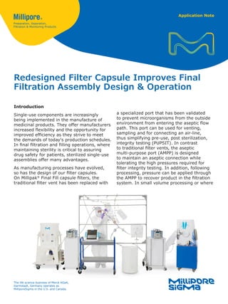
- 1. Application Note Redesigned Filter Capsule Improves Final Filtration Assembly Design & Operation Introduction Single-use components are increasingly being implemented in the manufacture of medicinal products. They offer manufacturers increased flexibility and the opportunity for improved efficiency as they strive to meet the demands of today's production schedules. In final filtration and filling operations, where maintaining sterility is critical to assuring drug safety for patients, sterilized single-use assemblies offer many advantages. As manufacturing processes have evolved, so has the design of our filter capsules. On Millipak® Final Fill capsule filters, the traditional filter vent has been replaced with a specialized port that has been validated to prevent microorganisms from the outside environment from entering the aseptic flow path. This port can be used for venting, sampling and for connecting an air-line, thus simplifying pre-use, post sterilization, integrity testing (PUPSIT). In contrast to traditional filter vents, the aseptic multi-purpose port (AMPP) is designed to maintain an aseptic connection while tolerating the high pressures required for filter integrity testing. In addition, following processing, pressure can be applied through the AMPP to recover product in the filtration system. In small volume processing or where The life science business of Merck KGaA, Darmstadt, Germany operates as MilliporeSigma in the U.S. and Canada.
- 2. 2 high value drug products are being processed, this recovery step can have significant economic benefits1 . In addition to the operational benefits, aseptic connections through the AMPP, rather than the filter inlet, offer opportunities for streamlined single-use assembly designs. In single-use redundant filtration (SURF) assemblies, where two sterilizing-grade filters are directly connected in series, the potential benefits of streamlined connections for both reducing hold-up volume and minimizing contamination risks are clear2 . This application note describes testing performed to assess volume loss in SURF assemblies and shows how both assembly design and filtration operations can be adapted to minimize volume and product loss in the system. Methods Assembly Design & Assessing Hold-Up Volume Two SURF assemblies were designed and constructed with Millipak® Final Fill 200 filters containing sterilizing-grade Durapore® 0.22 µm membrane. Due to the high pressures applied for integrity testing and fluid recovery, tubing material selection was critical. Silicone tubing with a hardness of 80 shore A was used for all lines off of the AMPP, while braided silicone tubing was used for other connections. In both assemblies, the primary filter is closest to the filling needles; the secondary, or redundant filter, is upstream of the primary filter. The first assembly, Figure 1A, is a traditional design, where the air-line connection is through the filter inlet, with a gas filter separating the air-line from the main flow path. Bags are attached to the AMPP to collect fluid from filter venting. Figure 1B shows an alternative, streamlined design that uses the AMPP for venting, sampling and air-line connections. In each of these assemblies, the gas filters contain sterilizing-grade hydrophobic membrane. Millipak® Barrier filters are being used in place of flush bags to simplify wetting, flushing and integrity testing of the primary and secondary sterilizing filters in the assembly. Each assembly was tested with three solutions of different viscosities: water and solutions of 15% and 18% Polyethylene Glycol (PEG) 20,000 with viscosities of approximately 25 and Figure 1 Schematic showing traditional (A) and streamlined (B) SURF assemblies. Integrity Tester Connection Integrity Tester Connection Integrity Tester Connection Integrit Conne Gas Filter Gas FilterGas Filter Gas Filter Vent Vent Bag Vent BagVent Bag Vent Bag Vent Bag Sampling Bag Sampling Bag Sampling Bag Sampling Bag AMPP AMPP AMPP AMPP Clamp Clamp Clamp Clamp Sterile Connector Millipak® Final Fill Filter Millipak® Final Fill Filter Millipak® Final Fill Filter Millipak® Final Fill Filter Millipak® Final Fill Filter Millipak® Barrier Filter Millipak® Barrier Filter Millipak® Barrier Filter AMPP B Integrity Tester Connection Integrity Tester Connection Integrity Tester Connection Gas Filter Gas FilterGas Filter Vent BagVent Bag Vent BagVent Bag Vent Bag Vent Bag Sampling Bag AMPP AMPP AMPPAMPP Clamp Clamp Clamp Clamp Millipak® Final Fill Filter Millipak® Final Fill Filter Millipak® Final Fill Filter Millipak® Final Fill Filter Millipak® Barrier Filter Millipak® Barrier Filter Vent Bag Vent Bag AMPP Millipak® Final Fill Filter ulation Vessel Millipak® Barrier Filter A
- 3. 3 Integrity Tester Connection Gas Filter Vent Bag Clamp M Fina Integrity Tester Connection Integrity Tester Connection Gas FilterGas Filter Vent Bag Vent BagVent Bag Vent Bag AMPPAMPP Millipak® Final Fill Filter Recirculation Vessel Balance Peristaltic Pump Millipak® Final Fill Filter Millipak® Barrier Filter Millipak® Barrier Filter Figure 2 Schematic showing the test system and parameters evaluated. 50 centipoise (cP), respectively. Unrecoverable product or hold-up volume was determined by measuring the change in mass of fluid collected in a recirculation vessel after filter draining or blow-down under pressure. For the higher viscosity solutions, volumes were corrected for solution density. Studies were performed with the main flow-path in both a horizontal position and at a 45-degree angle. In addition, unrecoverable product from the streamlined SURF design shown in Figure 1B was also determined with the flow-path at angles of 65 and 90 degrees. At least three measurements were made under each test condition and the mean values are shown. Before testing, the empty recirculation vessel was weighed, Figure 2. To measure the volume of liquid held in the system, the assembly was wet with test fluid to simulate standard processing conditions. The inlet, outlets and lines to vent bags were open before introducing liquid. Lines to the vent bags, Millipak® Barrier filters and air-lines were closed with clamps. Fluid was pushed through the assembly using the peristaltic pump at ~2.7 mL/min (10 psi) for water and ~200 mL/min (30 psi) for the PEG solutions. Air was vented from the filters and collected in vent bags. After venting, all vents were closed. The difference in weight of the recirculation vessel before and after assembly wetting was used to calculate the unrecovered liquid or hold-up volume. After wetting, the assembly was drained by gravity or subjected to pressurized air blow- down to determine how much product could be recovered using different methods. Recovery methods were performed sequentially: gravity drain, then blow-down at 10 psi, then 70 psi, which is above the membrane’s bubble point specification of 50 psi. The 10 psi blow-down was not performed on the traditional assembly design. After each recovery step, the difference in weight of the recirculation vessel was used to calculate the hold-up volume in the assembly which represents the liquid lost in the main flow path. Parameter Variables SURF Assembly Design Traditional, Streamlined Assembly Angle 0, 45, 65, 90 degrees Filter Draining Method Gravity drain, pressurized air at 10 or 70 psi Solution Viscosity 0 cP, 25 cP or 50 cP
- 4. 4 Gravity Drain Clamps on the outlet and air-lines were opened on both the traditional and streamlined assemblies; in the streamlined assembly, the AMPP was also open. Fluid was drained for 20 minutes into the recirculation vessel. Pressurized Air Blow-Down • Traditional assembly: blow-down at 70 psi was performed through the filter’s inlet ° The main flow-path upstream of the secondary filter was closed and the air source to that filter was connected to the air-line. ° The air-line was opened, the secondary filter was pressurized to 70 psi and drained liquid was collected. ° The air source was moved to the primary filter air-line, the secondary filter was isolated. • Streamlined assembly: blow-down was performed sequentially at 10 psi then 70 psi through the AMPP. ° Tubing connecting the vent and sample bags to the air-line were closed with valves. ° The air source was connected to the secondary filter through the AMPP, and the AMPP on the primary filter was closed. ° The air-line was opened, pressurizing the secondary filter to 10 psi and drained liquid was collected. ° The air source was moved to the primary filter air-line, connected through the AMPP, the secondary filter was isolated by clamping between the two filters and the primary filter was blown down at 10 psi. ° After the 10 psi test, the procedure was repeated with pressurized air at 70 psi. Vent Bag Recovery After filter venting, liquid was collected in the vent bags upstream of both the primary and secondary filters. At the end of each test, liquid in the vent bags was recovered by draining into a beaker. The weight of the beaker was used to determine the volume loss during filter venting. Results and Discussion Single-use filtration and filling assembly designs are generally unique to individual drug manufacturers with the arrangement of components dependent on the facility, product being manufactured and the features of individual component filters, sampling systems and connectors. Many manufacturers do not include product recovery steps in standard filtration operations; for larger processes, the benefits of increased product recovery may be outweighed by the additional steps and manufacturing time required. However, for small volume, high-value production processes, recovering volume held up in the system may be more appealing as unrecoverable product could translate into considerable economic loss. Adding a product recovery step requires connecting an air-source upstream of the filter inlet or vent to push product trapped in the filter and connecting lines into the header bag towards the end of filtration. The data presented below show how different parameters impact hold-up volume and benefit process design and economics. Assembly Design and Orientation Figure 3 shows the volume of unrecoverable liquid in the traditional (A) and streamlined (B) SURF assemblies in the absence of a recovery step and when the water in the assembly is drained by gravity. The overall volume of unrecoverable liquid in the streamlined SURF was slightly lower (290 mL) than that of the traditional assembly (330 mL). This 12% reduction in assembly hold-up volume was achieved by leveraging the functionality of the AMPP to minimize connections and tubing. Recovering liquid from the assembly using gravity is only possible if the main axis of the product flow-path is at an angle rather than in the horizontal position, Figure 3A. This modification to assembly orientation means at least 70% of liquid in the assemblies can be recovered using gravity. Increasing the angle of the main flow-path in the streamlined assembly from 45 to 65 or 90 degrees results in slightly higher volume recovery, which may be worth considering for high value products, Figure 3B. However, when the system is at 90 degrees, venting the filters became more difficult, reflected by the presence of more air and lower volume of liquid in the system.
- 5. 5 Benefits of Pressurized Air Blow-down for Product Recovery Figure 4 shows how blowing down the SURF assemblies with pressurized air enhances volume recovery. Blowing down at 70 psi, 20 psi above the membrane’s bubble point, recovers ~95% of the liquid in both the traditional and streamlined assemblies, irrespective of the assembly angle. Blowing down with pressurized air at 10 psi recovers over ~80% of liquid from the assembly. Although pressurized air at 10 psi recovers less volume than the higher pressure blow-down, for many processes this may be preferable: higher pressure blow-down may negatively impact product quality or risk the integrity of single-use connections. Figure 3 Impact of draining in traditional (A) and streamlined (B) SURF assemblies Figure 4 Impact of blow-down with pressurized air in traditional and streamlined SURF assemblies 350 300 250 200 150 100 50 0 UnrecoverableLiquid(mL) 70 psi Blowdown Traditional Assembly Streamlined Assembly 70 psi Blowdown10 psi BlowdownNo Recovery No Recovery 0º 45º 65º 90º A B Traditional Assembly Streamlined Assembly 450 400 350 300 250 200 150 100 50 0 UnrecoverableLiquid(mL) 450 400 350 300 250 200 150 100 50 0 UnrecoverableLiquid(mL) 45º 65º 90º 0º 45º Gravity Drain No Recovery Gravity DrainNo Recovery
- 6. 6 Impact of Fluid Viscosity on Recovery Figure 5 illustrates how solution viscosity impacts liquid hold-up from the streamlined assembly when either gravity draining, or blow-down procedures are implemented. For non-viscous solutions such as water, positioning the assembly at 45 degrees and letting the assembly drain by gravity markedly improves product recovery as discussed. However, for viscous solutions, gravity draining only recovers ~15% of liquid from the assembly and pressurized air is needed to increase the recovered volume. Importantly, if pressurized air is used, the viscosity of the solution is irrelevant: air pressure of 10 psi is sufficient to recover a similar volume of water and a 50 cP liquid solution from the SURF assembly. Although blow-down at 70 psi further increases volume recovery, the benefits of this over 10 psi blow-down are modest. However, for high- value products, high pressure offers an option to maximize the volume of liquid recovered and improve overall process economics. Vent Bag Recovery In SURF assemblies, filter venting can result in a considerable volume of product being collected in vent bags. With filters containing a typical vent, this product is effectively lost as the filter vent is not an aseptic connection to the flow-path. By contrast, the AMPP on Millipak® Final Fill filter has been validated as an aseptic connection, offering the opportunity to recover product lost in vent bags, without compromising sterility. To recover this product, two vent bags should be connected to the AMPP: one would collect water from venting during PUPSIT, and the second would collect the product lost during venting at the start of processing. Towards the end of processing, before the filter is blown-down with air, the vent bag containing product can be squeezed and the collected product recovered in the main flow-path. Figure 6 illustrates the cumulative benefits to product recovery in streamlined assemblies, as compared to traditional assemblies with no recovery steps. In each of these assemblies, the volume of product lost to venting with the non-viscous solution was approximately 80 mL; in traditional assemblies this would not be recovered. However, in streamlined assemblies containing Millipak® Final Fill filters this volume can be recovered through the AMPP, increasing recovery. Figure 5 Solution density and hold-up volume in traditional and streamlined SURF assemblies Figure 6 Comparison of hold-up volume in traditional SURF assembly (no recovery steps) with streamlined assembly including recovery steps (45-degree angle, 10 psi blow-down) 350 300 250 200 150 100 50 0 UnrecoverableLiquid(mL) 70 psi Blowdown Traditional Assembly Streamlined Assembly Recovery Method 70 psi Blowdown 10 psi Blowdown No Recovery Gravity Drain Gravity DrainNo Recovery Water 25 cP 50 cP 350 300 250 200 150 100 50 0 UnrecoverableLiquid(mL) Traditional Assembly Streamlined Assembly Assembly Type
- 7. 7 Figure 7 Schematic of optimized SURF assembly design with filters containing an aseptic multi- purpose port (AMPP) Integrity Tester Connection Integrity Tester Connection Gas Filter Gas Filter Vent Bag Vent Bag Sampling Bag Sampling Bag AMPP Sterile Connector Sterile Connector Millipak® Final Fill Filter Millipak® Final Fill Filter Millipak® Barrier Filter AMPP Parameter Recommendation SURF Assembly Design Using the AMPP, rather than the filter inlet, for connecting the air-line and/or vent bags shortens connections, resulting in slightly lower assembly hold-up volume than traditional SURF designs. Assembly Angle • If the assembly is to be drained by gravity, adjusting the orientation of the main flow-path in the SURF assembly to a 45-degree angle provides significant benefits to recovery. • Increasing the angle past 45 degrees maximizes recovery, but at 90 degrees, filter venting becomes challenging. Recovery Method • For water-like liquids, allowing the SURF assembly to drain by gravity reduces filter hold-up by ~70%. Adding a blow-down with air at 10 psi recovers over 80% of the volume. Blow-down at higher pressures further increases recovery but the impact to product quality and integrity of connections in the single-use assembly should be considered. • For viscous liquids of 25-50 cP, viscosity prevents efficient recovery using gravity alone, even when the assembly is oriented at a 45-degree angle. Recovery can be improved by blowing down with pressurized air at 10 psi or 70 psi. • Recovering product from vent bags through the AMPP, minimizes product loss in the SURF assembly. Table 1. Recommendations to minimize unrecoverable product in SURF assemblies Recommendations Collectively, these results highlight opportunities to minimize the volume of product lost in SURF assemblies. The ability of manufacturers to implement these different options will depend on their manufacturing environment, process scale, value of the drug product and motivation to maximize process efficiency. The summary below provides generalized recommendations for SURF assembly design and filtration operations to maximize recovery when using filters containing aseptic multi-purpose ports, Table 1. Figure 7 shows a schematic of a SURF assembly which leverages the advantages of the AMPP for integrity testing, blow-down and product recovery.
- 8. References 1 Improved Product Recovery using Blow-down and Millipak® Final Fill Filters Tech Note Lit No. TB4382EN 2 Millipak® Final Fill Filters Reduce Contamination Risk and Simplify Filtration System Design and Operations Tech Note Lit No. TN4709EN © 2020 Merck KGaA, Darmstadt, Germany and/or its affiliates. All Rights Reserved. MilliporeSigma, the vibrant M, Millipore, Millipak and Durapore are trademarks of Merck KGaA, Darmstadt, Germany or its affiliates. All other trademarks are the property of their respective owners. Detailed information on trademarks is available via publicly accessible resources. To place an order or receive technical assistance Please visit: EMDMillipore.com/contactPS For additional information, please visit: EMDMillipore.com Lit. No. MS_TN5539EN Ver. 1.0 09/2020 MilliporeSigma 400 Summit Drive Burlington, MA 01803