
Recommended
Recommended
More Related Content
Similar to TCXO Design Optimization for Improved Reliability
Similar to TCXO Design Optimization for Improved Reliability (20)
TCXO Design Optimization for Improved Reliability
- 1. Manufacturing Optimization for Improved Reliability in TCXO Oscillator Designs Michael Logue mlogue@mtronpti.com Production Engineering, MtronPTI, Yankton, SD/USA … Robert Cremins cremir@us.ibm.com Procurement Engineering, IBM, Hopewell Junction, NY/USA Abstract: The reliability of Temperature Controlled Crystal Oscillator designs can be improved through process optimization and controlling key process variables. Industry demands for a highly reliable TCXO combines the need for the frequency accuracy of complex oscillator designs with long-term reliability. A project intended to improve the long-term reliability focused on key process steps of oscillator thick film substrate assembly including design layout, solder application, solder reflow, and component circuit tuning. The project starting point was an oscillator design statistically capable of meeting the customer’s requirements. Design layouts were evaluated to minimize unbalanced or abnormal component stresses. The solder application and solder reflow process points were closely evaluated through a Design Of Experiments to provide the most robust construction. Component circuit tuning is a common practice in TCXO and OCXO products. Because of the manual nature of component selecting it is difficult to maintain quality control. Focused reliability testing, along with accelerated life testing verified or identified product and process improvements. Optimization was measured through a quantifiable increase of performance during qualification tests, accelerated life test, test to failure, and ultimately field performance. Selecting the correct test method to measure meaningful reliability improvement was a key element in the project. Test to failure and accelerated life tests identified reliability optimization opportunities on parts that successfully passed all required qualification tests. Introduction: As is often the case, a customer may have a timing application requirement which cannot be easily solutioned with any standard, catalog oscillator component offered by any supplier. Many of these situations may involve relatively low volumes but have extreme value to the customer due to their criticality in the ongoing functionality of the end product application. In these cases, suppliers willing to pursue such opportunities must first analyze the customer requirements and then compare them to both their current technology capabilities and the flexibility of their manufacturing processes. If an existing technology and its associated manufacturing process are both capable and flexible enough, it is both technologically possible and economically feasible for both the customer and the supplier to work together to develop and optimize an application specific solution. In the subject of this paper, the end customer required a Temperature Compensated Crystal Oscillator (TCXO) with customized specifications and an extremely high level of reliability performance over a multi-year period. TCXO Design overview: Common TCXO designs consist of a thermistor network with thermal characteristics approximately equal but opposite in temperature coefficient of the crystal. The thermistor network provides a voltage change creating a capacitance variation when combined with a varactor. The changing crystal load capacitance pulls the frequency oscillation of the crystal. The thermistor and varactor make up the TCXO temperature correcting circuit. Each crystal will require an individually tuned thermistor network. A well understood and highly stable thermal environment is required for accurate circuit measurement and tuning during manufacturing. As a result a TCXOs’ performance capability is closely tied to the capability of the manufacturing process to measure oscillator circuit variations over temperature and tune each individual device to the electrical values required. The first step in determining the feasibility of providing a solution to a customer’s requirement for an oscillator with nonstandard functionality and a high level of reliability is selecting the optimum overall design platform. The intrinsic reliability of an oscillator is based upon its fundamental design. (Christiansen, 1996, p. 6.1) As is the case with any oscillator, the analysis begins with the frequency and frequency tolerance over temperature required by the customer. The tighter the frequency requirement, the more complex the oscillator design typically is. In this case, a pre-existing hybrid microcircuit technology and manufacturing process employing discrete subcomponents mounted on a thick film substrate was chosen as the design platform. Once a product family has been found that can theoretically support the customer’s requirements, the design platform may need to be adjusted to fit the specific application. Several prototype builds may be required to verify the functionality of the design concept. In parallel with the prototype builds, the design team will also complete a computer simulation. “A large number of variables affect oscillator operation, and if the performance is inadequate, the apprentice is uncertain about a solution. Although much literature exists on the subject of oscillators, references typically address specific oscillator types. A fundamental understanding of the concepts is all too often buried in pages of equations.” (Rhea, 1990, p.xi-xii). TCXO Manufacturing Process overview: Hybrid microcircuit technologies commonly consist of thick-film printed on a ceramic substrate. A standard thick film process consists of screen-printing thick film paste onto the
- 2. f(t) substrate, drying the substrate then firing the substrate through a high temperature furnace. A major advantage of this design platform is the usage of thick film resistors which can be laser trimmed to precise values of +/-1.0%. Precise resistors, tuned to a specific value, increase a TCXO design’s capability and ultimately increase the flexibility of the design platform to provide a variety of customizable solutions. Process optimization is defined as achieving control by centering the process on the target output. Controlling key variables tightens the standard deviation of the output generated by a process. A better-targeted process with less deviation produces a more predictable, repeatable and reliable product. Thick film and component assembly process variables can easily impact the internal circuit performance of the TCXO and therefore must be identified and well understood. A baseline must be established and continuous, in-line measurements need to be implemented to monitor and control process manufacturing variations as they occur. TCXO Reliability Overview: Reliability is defined as the ability of a device to operate as intended under a defined set of conditions. Failure is used to describe a device that does not perform as intended. Reliability is measured as the probability that a device will perform satisfactorily for the predetermined time. A product’s failure rate can be broken down into three basic periods referenced to time; early failure period (infant mortality), intrinsic (random) failure period, and wear out failure period. The failure rate when charted verses time is commonly called the bathtub curve. “The general approach to reliability for electronic systems is to minimize early failures by emphasizing factory test and inspection and to prevent wear-out failures by replacing short-lived parts. Consequently, the useful life period characterized by stress-related failures is the most important period and the one (period) which design attention is primarily addressed.” (Christiansen, 1996, p.6.5) Manufacturing defects are generally the main cause of undesirable infant mortality failures and a major concern to end customers. “Mechanical defects such as weak wire bonds, poor pad adhesion, defective sub-components and partially cracked or chipped ceramics constitute a significant portion of infant mortality failures.” (Christiansen, 1996, p. 6.42). Electro-static Discharge (ESD) induced damage, which may also result from manufacturing or handling errors, can potentially cause latent defects which may manifest themselves as either early life failures or wear-out later in the products life. Ideally, a highly reliable product must have a very low early life failure rate together with a wear-out level that manifests itself only well after the end products’ anticipated life is over. To insure the overall reliability of a TCXO, production and assembly techniques as well as design and testing methodologies must be assessed. The reliability of an oscillator is commonly lower than the intrinsic level because of faulty procedures during manufacturing. (Christiansen, 1996, p. 6.1) Therefore, manufacturing must conduct a thorough process review to eliminate faulty procedures. Material and sub-component selection must also be evaluated for individual reliability performance under the specific TCXO circuit conditions. Independent components require the probability of system failure to be calculated as independent events. As the oscillator circuit becomes more complex with the addition of the temperature correcting circuit, the reliability of the system can decrease. “Even though the individual components of a system might have high reliabilities, the system as a whole can have considerably less reliability because all components that are in series must function. As the number of components in a series increases, the system reliability decreases.” (Stevenson, 2005, p.156). TCXO Qualification: As mentioned earlier, the customer required that a very high level of sustained reliability over a multi-year lifetime be demonstrated. The customer therefore defined a series of complex and detailed qualification procedures in order to detect the presence of any failure mechanism, wear-out phenomenon, manufacturing process weakness or other concern, which could potentially have, even a small, negative impact on this requirement. The results of these procedures were jointly analyzed by both the customer and the supplier. Both teams then jointly identified improvements to both the TCXO design and the associated manufacturing process that will be covered later in this paper. Once implemented by the supplier and optimized via ‘design of experiments’, selected portions of these qualification procedures were later repeated to validate the effectiveness of the improvements. The following are the high lights of these qualification procedures. First, the customer required that several ‘production ready’ samples be submitted for a ‘construction analysis’ report. A construction analysis involves a complete decapsulation, dissection, physical analysis and general reverse engineering of the oscillator component. All critical dimensions, interfaces and materials are analyzed, photographed and/or documented via assorted analytical time Intrinsic failure Wear-out failure Early failure
- 3. means such as EDX, X-ray, cross-sectioning and extremely high power magnification equipment (SEM). In addition, the level of workmanship and process consistency both within the component and between components made via the same manufacturing process is readily evident and can therefore be assessed. The final report, which can be shared between customer and supplier, includes this assessment as well as identification of potential concerns. The personnel assigned by the customer to perform this work and prepare the final report, ideally have a wealth of historical experience, which they can bring to each analysis. The report has an additional, continuing value in that it provides for a common baseline understanding of the component structure, which enables both customer and supplier to have a knowledgeable dialog on both potential weaknesses and proposed improvements. As already discussed, the reliability of a component is largely a function of the manufacturing process which produces it. A component with a high degree of interconnect complexity will require a large number of process steps to produce. The greater the number of process steps, the greater the potential for error or weakness. Due to the complexity of this TCXO, the customer felt strongly that the qualification process needed to include a full review and assessment of the manufacturing process. This was performed via on-site audit visits by customer process and material personnel with significant expertise and experience. During these visits, general capability, operator certification and quality control practices of the suppliers’ factory are first discussed in detail. This is then followed by an in depth review and explanation, on paper, of the specific manufacturing process steps used to produce the TCXO in question to insure a common understanding of the purpose and details of each step. The customer is then physically taken to and shown the work area and/or manufacturing tool set associated with each process step in sequence starting with incoming receipt of raw materials and finishing with final TCXO test, pack and ship. At each manufacturing step, process control methods and resultant metrics are reviewed, general cleanliness and organization are assessed and ‘on- the-spot’ interviews are conducted with operators to determine their capability and understanding of their respective processes. Supplier manufacturing, design and product engineering personnel from both management and working level ranks participate together with the customer during each stage of this process which can take several days to complete. At the conclusion of the visit, the customer compiles their findings, observations and concerns into a presentation given directly and immediately to the supplier management and staff. Findings are broken in to major concerns, minor concerns, recommendations and items requiring follow-on explanation. Soon after the visit, the customer provides the supplier with a detailed, written report, which includes all the findings. As with the construction analysis report, the audit report provides for a common vehicle between supplier and customer to communicate and track corrective actions and improvements to the manufacturing process. The last portion of the qualification procedure that we will discuss is the actual reliability testing typically referred to as ‘life’ or ‘accelerated stress’ testing. Accelerated testing is effective in detecting the existence of and measuring the level of assorted failure mechanisms within the TCXO throughout its’ anticipated life. By increasing the operating temperature and/or operating voltage/current on test samples, acceleration can be achieved and the devices’ anticipated life cycle can be simulated. A proper reliability test matrix is designed to detect the presence of and measure the level of the various early life failure and/or wear-out mechanisms, which might be present in the TCXO. As with manufacturing process steps, a device with numerous interconnects, materials and sub- components could be susceptible to a wide variety of mechanisms. Therefore the testing must be designed to detect a wide variety of mechanisms. Another factor in defining the test matrix is the equipment and test capabilities available. As is often the case, due to the need to have appropriate device level test equipment to periodically test electrical parameters of devices under stress, supplier resources were used for the majority of the testing. As with the construction analysis, all test cells consisted of production level samples made, where possible, from different manufacturing runs. The following table describes the major reliability stress tests performed on the TCXO:
- 4. Focused Improvement Areas: Through the use of these qualification procedures, the following items within the TCXO product design and its associated manufacturing process were discovered and selected for focused improvement: • The TCXO construction employs a two sided substrate, mounted on a metal can header base assembly. The bottom of the substrate is connected to the header base via non-conductive epoxy, which also acts to electrically and physically isolate the header from the substrate. The general internal construction of the device is shown below. Elevated temperature and voltage life testing produced several frequency shift failures late in the test. The root cause was determined to be a high temperature wearout of the non-conductive epoxy and substrate glassivation, which resulted in a leakage path from header to substrate through the non- conductive epoxy and glassivation in areas of minimal spacing between base and substrate. The construction analysis report and audit confirmed that variations were possible in the amount of applied non-conductive epoxy and associated header to substrate spacing. Applying an industry standard acceleration model for dielectric breakdown indicated that the failure rate adder for this mechanism under normal use conditions was extremely small however improvements were possible. • The integrity of the electrical connections between the header I/O pins and the substrate is a function of the material used to make the contacts, the method applied and the amount of contact area. Also, as is evident in the depiction of the device construction shown, the integrity of these connections is largely dependent on the same non-conductive epoxy connection discussed above which provides the basic mechanical strength to connect the header to the substrate. It was determined that variations in this header to substrate non-conductive epoxy bond or excessive customer handling after shipment could result in cracking or degradation at one or more of the I/O contact points which in turn could cause intermittent TCXO output failures. This mechanism could possibly escape initial customer test and cause an intermittent ‘no oscillation output’ field failure later in life. • The TCXO contains a number of discrete components mounted via tin-lead based solder on to silver palladium runs on a ceramic substrate. TEST TYPE TEST CONDITIONS Preconditioning Assorted temperature and environmental extremes to simulate transportation, storage and attachment of the component to the next level assembly. This includes temperature cycling, humidity soaking, flux application and temperature shocking to simulate solder assembly. This procedure is performed on all stress test samples prior to the start of test. High Temperature Operating Life Tests Several test cells are used with different applied voltages varying from nominal to max Vcc and temperatures varying from 85 to 125 degrees C. All samples are fully loaded. Tests are conducted for 2000 hours and all samples are extracted periodically to measure and record electrical parametrics. Temperature Cycling Samples are unbiased and put in a temperature cycling chamber. Several test cells are used with temperature deltas varying from 100 to 165 degrees C and different ramp rates and/or number of cycles/per hour. A minimum of 1000 cycles is required but tests with smaller temperature deltas are extended longer to better understand wearout mechanisms. Temperature Shock Samples are unbiased and put in a temperature shock chamber. Several test cells are used with temperature deltas larger than that of temperature cycling. Ramp rates and/or number of cycles/per hour are also more aggressive than that of temperature cycling. A minimum of 100 cycles is required but tests are again extended to better understand wearout mechanisms. Accelerated Aging Samples are unbiased and put in a temperature chamber. Again several test cells are used with temperatures varying from 85 to 125 degrees C Drop Shock & Mechanical Vibration Assorted drop and mechanical tests based largely on MIL standards with minor changes to address customer application specific concerns HEADER CERAMIC SUBSTRATE Thickfilm i it Solder CRYSTAL Pin Epoxy Pin
- 5. It is well known in such situations that the tin within the solder composition can to be absorbed into the silver and possibly degrade the integrity of the solder joints involved. Further, the application of heat accelerates this absorption and degradation process. This phenomenon is unavoidable without radically changing the materials involved. It is however considered benign if proper process controls and associated temperatures are well controlled and resultant parts are properly tested. In the case of this TCXO, there are numerous manufacturing process and reliability test steps involving heat application, which could accelerate this mechanism. Construction analysis and accelerated testing indicated the presence of this mechanism at varying levels. As discussed, this mechanism is a concern since it causes degraded solder joints which can manifest themselves as intermittent electrical failures. Yet, some level of this mechanism is unavoidable. The challenge was to optimize the device construction and manufacturing process to minimize this phenomenon and, as an additional precaution, establish appropriate screening methods to detect worst case situations and prevent them from being shipped to the customer. • In line with the above challenge is the difficulty associated with defining and controlling the processes associated with solder dispensing and reflowing. The amount of solder and the reflow temperature will affect not only the amount of tin absorption but the overall integrity of all the internal solder joints. Unfortunately, due to the detrimental impact of heat on the components within the TCXO and the high performance customer specifications, a traditional enclosed reflow oven with a well controlled temperature profile could not be used. Instead, open air equipment, which focused heat on the bottom of the substrate while minimizing heat on the top side components was required. Although necessary, this process methodology created additional variables, which needed to be assessed and controlled. The customer audit identified this process step and its associated inspection areas as a major concern and focus area for improvement. Design & Assembly Enhancements: The two-sided TCXO construction requires the mounting of a ceramic substrate on a metal header assembly. The bottom side of the circuit, with the base conductor metal of a silver palladium compound, is connected via non- conductive epoxy to the metal header base. Reliability testing along with failure mode and effects analysis provided an opportunity to improve this design. High Temperature Operating Life tests, employing elevated temperature, voltage and current proved to be effective in detecting a measurable, potential wear-out mechanism. Between one and two thousand hours of testing at 125 degree C., several minor frequency shift failures were encountered. Electrical analysis determined that the frequency shift was caused by a low resistance leakage path between the bottom of the substrate and the metal header. Subsequent physical analysis concluded that the leakage path resulted from a combination of wear-out of the non- conductive epoxy and substrate glassivation materials together with manufacturing variation in the physical distance between header and substrate. The net effect was a change in the oscillators’ output frequency which obviously could have an adverse impact on the customer. The usage specifications of both the non-conductive epoxy and the glassivation were reviewed and discussions were held with the suppliers of both materials. Unfortunately, the capability and performance of each material at the stress temperatures applied was unclear. Therefore it was difficult to determine a proper acceleration factor and assess the impact of this mechanism over the life of the TCXO. By using a standard arrehenius model, plotting the time-to-fail distribution and varying the activation energy (Ea), the customer estimated the range of potential impact of this failure mechanism as follows: Time Interval (in hours) Interval Failure rate with Ea=1.0ev Interval Failure rate with Ea=0.5ev 0-8620 0 72 ppm/thousand hours 8620-20K 0 293 ppm/thousand hours 20-40K 0 527 ppm/thousand hours 40-60K 0 694 ppm/thousand hours 60-100K 0.4 ppm/thousand hours 800 ppm/thousand hours Although potentially insignificant, the uncertainty involved in modeling this mechanism was enough to warrant improvement in the design construction and associated manufacturing process. To minimize the likelihood of substrate to metal header shorting, the initial thought was to modify the TCXO construction by increasing and guaranteeing a fixed, consistent distance between the substrate and metal header base with the use of physical assembly aids inserted between substrate and header during manufacturing. However, the increased distance adversely affected the adhesive strength of the non-conductive epoxy connection. The strength of this adhesion had already been identified as a concern since the mechanical integrity of the I/O pins connection to the substrate is completely dependent on the non-conductive epoxy adhesion. Changing the composition and application of the I/O pin to substrate connection from conductive epoxy to solder and eliminating the non- conductive epoxy all together was considered and
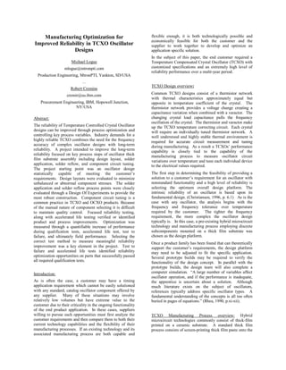
- 6. experimented with in an attempt to increase the strength of these connections. Although the soldered pins demonstrated increased mechanical strength, the high temperatures associated with any type of additional soldering process proved detrimental to the nearby components and associated solder joints already placed on the substrate. Temperature cycling stress testing proved that the additional heat treatment further aggravated the tin absorption and associated solder joint integrity. As a result, the conductive epoxy connections had to be retained. To compensate and address the concerns, the amount and placement of the non-conductive epoxy was modified to optimize adhesion and strength. The original design used two separate epoxy bond applications with one at each end of the header base. Uneven epoxy dispensing and manual placement allowed for potential unevenness or ‘see-sawing’ within a module. The modified design employed a single and larger amount of epoxy placed in the center of the base. This facilitated the use of the physical assembly aids which in turn insured a consistent and even spacing between the header base and substrate. Also, the cleanliness requirements and incoming inspection criteria for the procured metal header base were tightened to insure an optimal surface for epoxy adhesion. The header base pin height requirement was also increased compared to the standard height to compensate for the higher substrate mounted position and also provide additional contact area and increased strength for the conductive epoxy pin connections. The modified assembly technique was again tested via the same High Temperature Operating Life methodology. The wear-out mechanism, previously detected between one and two thousand hours of test, was no longer evident. The increased and consistent distance between header and substrate proved to be effective. In depth thermal shock, vibration and drop testing was then performed to assess the overall mechanical strength of the modified TCXO construction. To demonstrate the effectiveness of the design, three groups of test samples were built. The first group of samples was built with oil intentionally applied to the metal header to represent contamination which would negatively impact epoxy adhesion (labeled ‘C’ for contaminated). The second group was constructed without any epoxy (labeled ‘N’ for no epoxy) to simulate the worst case condition of no adhesion. The third group was constructed normally (labeled ‘G’ for good). Samples from each group were tested both as individual components and as part of assemblies after being attached to printed circuit boards to better simulate anticipated application conditions and normal stress on the I/O pins. Loose parts underwent incremental drop testing from 1 to 36 inches and incremental thermal shocking of 10 cycles starting at -40 to 60 with increasing 10 degree increments. Card-assembled parts underwent incremental thermal shock and drop as well as incremental thermal shock and vibration. The results, depicted in the table below, demonstrated an acceptable level of mechanical robustness even in samples made without the non-conductive epoxy. Failures occurred primarily due to extreme thermal shocks which were deemed well beyond anticipated typical usage. Solder Joint and Assembly process Optimization: The next challenge was associated with the solder attachment of the various sub-components within the TCXO assembly. As discussed, tin within standard solder composition can to be absorbed into the silver-palladium, causing brittleness in the contact area and degraded adhesion of the silver palladium to its ceramic base. This can manifest itself as a weak or degraded solder joint which may crack or even open as a result of normal expansion and contraction of materials and sub-components within the TCXO. It may also appear as an intermittent electrical failure which may or may not be screened out during normal electrical or visual inspections. This absorption mechanism is further accelerated by any heat application. Unfortunately, the manufacturing process associated with this custom TCXO required several heat treatments for assorted epoxy curing steps well after component soldering. As a result, this mechanism which could result in either early life or wear-out failures was targeted for in-depth analysis. Although traditional Temperature Cycling stress testing did not result in any electrical failures, physical analysis of post stress samples indicated a level of potential variability which was deemed unacceptable by the customer. A high magnification cross-sectional photo of a worst case, post stress solder joint showing degradation and fracturing at the silver-palladium to ceramic interface is shown below. A Design of Experiments was conducted to assess the impact of temperature on the resultant solder joint integrity. “DOE techniques offer a structured approach for changing No Fails 1 fail @90C Tmax 1 fail @100CTmax 1 fail @120CTmax 1 fail @130CTmax No Fails Thermal-Shock (-40 to130 C) No FailsNo FailsG No Fails1fail @120 C/ 30” (Failed in drop test) N No FailsNo FailsC PARTS ON CARDS No FailsG No FailsN No FailsC LOOSE PARTS Thermal-Shock &Vibration (-40 to 150 C/ .01 to 1G2 /Hz) Thermal-Shock &Drop (-40 to 130 C/ 1to 36”) Drop (1 - 36”) RESULTS No Fails 1 fail @90C Tmax 1 fail @100CTmax 1 fail @120CTmax 1 fail @130CTmax No Fails Thermal-Shock (-40 to130 C) No FailsNo FailsG No Fails1fail @120 C/ 30” (Failed in drop test) N No FailsNo FailsC PARTS ON CARDS No FailsG No FailsN No FailsC LOOSE PARTS Thermal-Shock &Vibration (-40 to 150 C/ .01 to 1G2 /Hz) Thermal-Shock &Drop (-40 to 130 C/ 1to 36”) Drop (1 - 36”) RESULTS
- 7. many factor settings within a process at once and observing the data collectively for improvements/degradations.” (Breyfogle, 2003, p.549). Test vehicles were constructed and reflowed, first with a constant temperature (210 degrees C.) and varying the reflow time from 5 to 40 seconds, then with a constant time (20 seconds) and varying temperature. EDAX scans were then performed to determine material composition and assess deltas in the level of resultant tin penetration. Results, shown below, indicate a dramatic increase in the tin penetration level occurs from a relatively small increase in either reflow time or temperature. It is therefore clear that the reflow process as well as any subsequent heat treatment must be tightly controlled in order to minimize variations in this mechanism. Obviously, any additional reflows or component reworking in manufacturing will further increase the penetration and cause a drop in adhesion. This underscores the importance of not reworking or replacing components after the initial reflow. C o n s t a n t T e m p . ( 2 1 0 C ) C o n s t a n t T im e ( 2 0 s ) 2 1 0 C 2 3 0 C 5 s 4 0 s A g - P d S n - P b C e r a m i c I n t e r f a c e With this knowledge in hand, solder paste storage, solder amount, solder application, component mount and solder reflow processes were all reviewed in depth to drive consistent and improved process control. Enhancements were first made in the solder stencil design to reduce solder application and thickness variation across the substrate. Along with this, the solder dispense tool calibration procedures and associated thickness measurement methods were reviewed and updated where needed. Cleaning and storage of stencils was also identified as a potential concern and improvement actions were again taken where appropriate. Focus was then placed on the reflow process itself. Reflow conditions have always been closely tied to product reliability. Inappropriate reflow process can damage components or substrate integrity. During solder reflow; maximum temperature, rate of heating, time spent at each temperature zone, heat control, cooling rate and belt speed must all be monitored continuously. As mentioned earlier, non-conventional open air reflow equipment was required in the assembly of this TCXO product to minimize detrimental high temperature impacts on the sub- component content performance. It was determined that normal variations in the manufacturing room temperature and/or air flow could change the reflow conditions seen by the TCXO. As a result, the supplier modified their physical assembly area to reduce any variation and implemented equipment to closely maintain and monitor the air conditions near and around the reflow equipment. Also, new reflow profiling vehicles, updated measurement methodologies and a tighter allowable reflow profile were all defined and implemented. The TCXO substrate itself was then modified to improve the overall robustness of the design. First, the wiring layout and placement of sub-components was changed with a careful eye to identify and eliminate any area where unnecessary mechanical stress could be put on solder joints due to normal thermal expansion or contraction of materials during either TCXO manufacturing, next level assembly or end product life. For example, sharing of a pad between subcomponents was not allowed. Second, the thickness of the silver palladium wiring runs on the substrate was increased at and near any location where solder was to be applied. This increased the silver material content at the solder joint and thus decreased the impact of any tin absorption. TCXOs and Oven Controlled Crystal Oscillators (OCXO) often require component ‘selecting’ after the oscillator has been assembled because of variations in multiple components. Stacked up tolerances often exceed the design window for tuning the oscillators to frequency specification. A tolerance analysis is used to show the design’s operating window. The tolerance build up of varying circuit components can lead to an extreme variation in a critical variable. This variation may start the oscillator at a frequency outside of the tuning window. Component ‘selecting’ or replacing is used to set the oscillator frequency back into the tuning window. During component selecting, typically a previously mounted component is unsoldered, removed and replaced with an alternate component of a different electrical value. In manufacturing, this is often a manual, soldering rework operation prone to reliability failures. Such failures could easily be caused by the tin absorption mechanism discussed earlier and greatly aggravated by the additional focused heat application associated with solder rework. It is therefore clear that this component selecting or solder rework process must be avoided if a high reliability product is desired. To achieve this, tight tolerance components with values statistically chosen to center the tuning window must first be used. Second, a manufacturing process with high accuracy laser trimming of thick-film resistors with a wide tuning window is applied. The wide tuning window allows a larger window of oscillator frequencies to be tuned. Laser tuned resistors and/or capacitors provide a clean and efficient method of varying the oscillator circuit’s electrical characteristics and greatly minimize the need to select or replace components resulting in a more reliable TCXO. Finally, appropriate final screening and test techniques were established and implemented to detect and eliminate any potentially weak solder joints prior to customer shipment. Prior to final frequency tuning, all units are subjected to 168 hours of 125 degree C. bake followed by 10 temp cycles with a minimal temperature delta of 100
- 8. degrees C. This not only serves to aggravate and detect weak solder joints but also to age the on-board crystal. Also, all completed units undergo temperature step testing in which all parameters are measured at various temperatures beginning at the maximum operating temperature and proceeding to the minimum temperature in 5-10 degree decrements. This sequence was proven to be effective in detecting weak solder joints under stress since the high temperature first creates expansion which is followed closely by contraction as the temperature drops. The improvements in the solder process, testing and resultant solder joint integrity were verified using component shear testing, component pull strength measurements and extensive reliability testing employing both temperature cycling and temperature shock stress. Results indicated that a reliable bond was achieved with strong adhesion and minimal variability between units. Conclusion: Manufacturing optimization begins with a design capable of meeting the customer’s specification. The adaptation and modification of a standard design platform for a high reliability application will require a thorough design and manufacturing process review to understand any potential failure mechanism. The manufacturing process has a large impact on early life failures. Design for manufacturability improvements along with increased process monitoring and controls will improve the reliability of a product. Accelerated stress testing also provides key information for reliability prediction as well as identifying weak links in a design or its’ manufacturing assembly methods. “Reliability prediction, Failure Modes and Effects Analysis (FMEA), and reliability growth techniques represent prediction and design evaluation methods that provide a quantitative measure of how reliably a design will perform. These techniques help determine where a design can be improved. Since specified reliability goals are often contractual requirements which must be met along with functional performance requirements, these quantitative evaluations must be applied during the design stage to guarantee the equipment will function as specified for a given duration under the operational and environmental conditions of the intended use.” (Christiansen, 1996, p.6.11). Direct participation by the customer in the suppliers’ optimization process is not typically the norm. However, a close supplier and customer relationship can take advantage of the technical resources of both companies. In addition to producing high performance and highly reliable products, such relationships can result in quicker design cycles as well as shared responsibility for design and process changes. The supplier benefits from the experience and can incorporate resultant improvements into other product families. The customer will benefit, not only from the improved resultant product, but from an increased understanding of the product they are purchasing and the capability of the supplier who is manufacturing it. Reference: Christiansen, Donald (1996). Electronics Engineer’s Handbook (4th Ed). McGraw-Hill: Jurgen, Torrero, and Fink. Rhea, Randall W. (1990). Oscillator Design & Computer Simulation. P T R Prentice Hall: Rottino. Stevenson, William J. (2005). Operation Management (8th Ed). McGraw-Hill Irwin: Hercher Viswanadham, Puligandla, & Singh, Pratap (1998). Failure Modes and Mechanisms in Electronic Packages. Chapman & Hall: Breyfogle, Forrest W. III (2003). Implementing Six Sigma: Smarter Solutions Using Statistical Methods (2nd Ed). John Wiley & Sons: Suhir, Ephraim (2005). Reliability and Accelerated Life Testing. Semiconductor Packaging, 18. Acknowledgements: Special thanks to Pedro Chalco for his participation, test work, knowledge, guidance and recommendations throughout the qualification, analysis and improvement process. Also a special thanks to David Bushong for his technical guidance and material expertise.