SlideShare a Scribd company logo
1 of 201
Download to read offline
Unit 10Unit 10Unit 10
SIMPLE HARMONICSIMPLE HARMONIC
MOTION AND WAVESMOTION AND WAVES
SIMPLE HARMONIC
MOTION AND WAVES
• explain the diffraction of radiowaves but not of T.V waves (transmission can be heard in
such areas where the waves cannot reach directly).
Science, Technology and Society Connections
The students will be able to:
After studying this unit, students will be able to:
• state the conditions necessary for an object to oscillate with SHM.
• explain SHM with simple pendulum, ball and bowl examples.
• draw forces acting on a displaced pendulum.
• solve problems by using the formula T = 2π ll /g for simple pendulum.
• understand that damping progressively reduces the amplitude of oscillation.
• describe wave motion as illustrated by vibrations in rope, slinky spring and by
experiments with water waves.
• describe that waves are means of energy transfer without transfer of matter.
• distinguish between mechanical and electromagnetic waves.
• identify transverse and longitudinal waves in mechanical media, slinky and springs.
• define the terms speed (v), frequency( f ),wavelength (λ), time period (T), amplitude,
crest, trough, cycle, wavefront, compression and rarefaction.
• derive equation v = f λ.
• solve problems by applying the relation f = 1/T and v = fλ.
• describe properties of waves such as reflection, refraction and diffraction with the
help of ripple tank.
l g
A body is said to be vibrating if it moves back and forth or to
and fro about a point. Another term for vibration is
oscillation. A special kind of vibratory or oscillatory motion is
called the simple harmonic motion (SHM), which is the main
focus of this chapter. We will discuss important
characteristics of SHM and systems executing SHM. We will
also introduce different types of waves and will demonstrate
theirpropertieswiththehelpofrippletank.
10.1  SIMPLEHARMONICMOTION(SHM)
In the following sections we will discuss simple harmonic
motion of different systems. The motion of mass attached to
a spring on a horizontal frictionless surface, the motion of a
ball placed in a bowl and the motion of a bob attached to a
stringareexamplesofSHM.
MOTION OF MASS ATTACHED TO A SPRING
One of the simplest types of oscillatory motion is that of
horizontal mass-spring system (Fig.10.1). If the spring is
stretched or compressed through a small displacement x
from its mean position, it exerts a force F on the mass.
According to Hooke’s law this force is directly proportional to
thechangeinlengthxofthespringi.e.,
........ (10.1)
where x is the displacement of the mass from its mean
position O, and k is a constant called the spring constant
definedas
The value of k is a measure of the stiffness of the spring. Stiff
springs have large value of k and soft springs have small value
of k.
It means that the acceleration of a mass attached to a spring
is directly proportional to its displacement from the mean
position. Hence, the horizontal motion of a mass-spring
systemisanexampleofsimpleharmonicmotion.
For your information
A spider detects its prey due to
vibrationproducedintheweb.
2
SIMPLE HARMONIC MOTION AND WAVES
Not For Sale – PESRP
As
or
Fig.10.1: SHM of a mass-spring
system
a - x ........ (10.2)
F = 0
B
B
O
O
A
A
F
F
(a)
(b)
x
(c)
x = 0
x
F = - k x
k = - F
x
k = - ma
x
a = - xk
m
F = ma
x
Therefore,
SIMPLE HARMONIC MOTION AND WAVES
3
For your information
Kinetic and potential energy at
different positions in a
mass–springsystem.
x = -A x = 0 x = +A
K.E =0
P.E = max
P.E = 0
K.E = max
P.E = max
K.E = 0
The negative sign in Eq. 10.1 means that the force exerted by
the spring is always directed opposite to the displacement of
the mass. Because the spring force always acts towards the
meanposition,itissometimescalledarestoringforce.
Arestoringforcealwayspushesorpullstheobjectperforming
oscillatorymotiontowardsthemeanposition.
Initially the mass m is at rest in position O and themean
resultant force on the mass is zero (Fig.10.1-a). Suppose
the mass is pulled through a distance x up to extreme
position A and then released (Fig.10.1-b). The restoring
force exerted by the spring on the mass will pull it
towards the position O. Due to the restoring forcemean
the mass moves back, towards the mean position O. The
magnitude of the restoring force decreases with the
distance from the mean position and becomes zero at O.
However, the mass gains speed as it moves towards the
mean position and its speed becomes maximum at O.
Due to inertia the mass does not stop at the mean
position O but continues its motion and reaches the
extreme position B.
As the mass moves from the position O to the extrememean
position B, the restoring force acting on it towards the mean
position steadily increases in strength. Hence the speed of
themassdecreasesasitmovestowardstheextremeposition
B. The mass finally comes briefly to rest at the extreme
position B (Fig. 10.1-c). Ultimately the mass returns to the
meanpositionduetotherestoringforce.
This process is repeated, and the mass continues to oscillate
back and forth about the mean position O. Such motion of a
mass attached to a spring on a horizontal frictionless surface
isknownasSimpleHarmonicMotion(SHM).
The time period T of the simple harmonic motion of a mass
‘m’attachedtoaspringisgivenbythefollowingequation:
Not For Sale – PESRP
´
m
T 2 ......... (10.3)
Tidbits
A human eardrum can oscillate
back and forth up to 20,000
timesinonesecond.
Quick Quiz
What is the displacement of an
objectinSHMwhenthekinetic
and potential energies are
equal?m
k
T
SIMPLE HARMONIC MOTION AND WAVES
BALLANDBOWLSYSTEM
The motion of a ball placed in a bowl is another example of
simple harmonic motion . When the ball is at the(Fig 10.2)
mean position O, that is, at the centre of the bowl, net force
acting on the ball is zero. In this position, weight of the ball
acts downward and is equal to the upward normal force of
the surface of the bowl. Hence there is no motion. Now if we
bring the ball to position A and then release it, the ball will
start moving towards the mean position O due to the
restoring force caused by its weight. At position O the ball
gets maximum speed and due to inertia it moves towards the
extreme position B. While going towards the position B, the
speed of the ball decreases due to the restoring force which
acts towards the mean position. At the position B, the ball
stops for a while and then again moves towards the mean
position O under the action of the restoring force. This to and
fro motion of the ball continues about the mean position O
till all its energy is lost due to friction. Thus the to and fro
motion of the ball about a mean position placed in a bowl is
anexampleofsimpleharmonicmotion.
MOTIONOFASIMPLEPENDULUM
A simple pendulum also exhibits SHM. It consists of a small
bob of mass ‘m’ suspended from a light string of length ‘ ’
fixed at its upper end. In the equilibrium position O, the net
force on the bob is zero and the bob is stationary. Now if we
bring the bob to extreme position A, the net force is not zero
(Fig.10.3). There is no force acting along the string as the
tension in the string cancels the component of the weight
mgcosθ.Hencethereisnomotionalongthisdirection.
Thecomponentoftheweightmgsin isdirectedtowardstheθ
mean position and acts as a restoring force. Due to this force
the bob starts moving towards the mean position O. At O, the
bob has got the maximum velocity and due to inertia, it does
not stop at O rather it continues to move towards the
extreme position B. During its motion towards point B, the
velocity of the bob decreases due to restoring force. The
velocityofthebobbecomeszeroasitreachesthepointB.
4
Fig. 10.3: Forces acting on a
displaced pendulum. The
restoring force that causes the
pendulum to undergo simple
harmonic motion is the
component of gravitational
force mg sinθ tangent to the
pathofmotion
Not For Sale – PESRP
o mgsinθ
mg mgcosθ
A
TT
B
θ
T
S
w = mg
Mean
position
m m
m
l
l
Fig. 10.2: When a ball is gently
displaced from the centre of a
bowl it starts oscillating about
the centre due to force of
gravity which acts as a
restoringforce
B Ball
R
A
w = mg
O
Bowl
5
The restoring force mgsin still acts towards the meanθ
position O and due to this force the bob again starts moving
towards the mean position O. In this way, the bob continues
itstoandfromotionaboutthemeanpositionO.
It is clear from the above discussion that the speed of the bob
increaseswhilemovingfrompointAtoOduetotherestoring
force which acts towards O. Therefore, acceleration of the
bob is also directed towards O. Similarly, when the bob
moves from O to B, its speed decreases due to restoring force
which again acts towards O. Therefore, acceleration of the
bob is again directed towards O. It follows that the
acceleration of the bob is always directed towards the mean
positionO.HencethemotionofasimplependulumisSHM.
Wehavethefollowingformulaforthetimeperiodofasimple
pendulum
......... (10.4)
Fromthemotionofthesesimplesystems,wecandefineSHM
as:
Simple harmonic motion occurs when the net force is
directly proportional to the displacement from the mean
position and is always directed towards the mean
position.
In other words, when an object oscillates about a fixed
position (mean position) such that its acceleration is directly
proportional to its displacement from the mean position and
is always directed towards the mean position, its motion is
calledSHM.
ImportantfeaturesofSHMaresummarizedas:
i. A body executing SHM always vibrates about a fixed
position.
ii. Its acceleration is always directed towards the mean
position.
iii. The magnitude of acceleration is always directly
proportional to its displacement from the mean
Time Period
Time period of a pendulum is
the time to complete one
cycle.
Check Your Understanding
Tell whether or not these
motions are examples of
simpleharmonicmotion:
(a) up and down motion of a
leaf in water pond (b) motion
of a ceiling fan (c) motion of
hands of clock (d) motion of a
plucked string fixed at both its
ends (e) movement of honey
bee.
SIMPLE HARMONIC MOTION AND WAVES
ß
l
T 2
Not For Sale – PESRP
l
g
For your information
The period of a pendulum is
independent of its mass and
amplitude.
T
SIMPLE HARMONIC MOTION AND WAVES
position i.e., acceleration will be zero at the mean
position while it will be maximum at the extreme
positions.
iv. Its velocity is maximum at the mean position and zero
attheextremepositions.
Now we discuss different terms which characterize simple
harmonicmotion.
Vibration: One complete round trip of a vibrating body about
itsmeanpositioniscalledonevibration.
Time Period (T ): The time taken by a vibrating body to
completeonevibrationiscalledtimeperiod.
Frequency ( f ): The number of vibrations or cycles of a
vibrating body in one second is called its frequency. It is
reciprocaloftimeperiodi.e.,f=1/T
Amplitude (A): The maximum displacement of a vibrating
body on either side from its mean position is called its
amplitude.
Example10.1:Findthetimeperiodandfrequencyofasimple
-2
pendulum1.0mlongatalocationwhereg=10.0ms .
Solution:
-2
Given, =1.0m,g=10.0ms .
Usingtheformula,
Byputtingthevalues
=1.99s
Frequencyofsimplependulumisgivenby
f = 1/T = 1/1.99 s = 0.50 Hz
10.2 DAMPEDOSCILLATIONS
Vibratory motion of ideal systems in the absence of any
friction or resistance continues indefinitely under the action
of a restoring force. Practically, in all systems, the force of
friction retards the motion, so the systems do not oscillate
indefinitely. The friction reduces the mechanical energy of
6
For your information
Christian Huygens invented
the pendulum clock in 1656.
He was inspired by the work of
Galileo who had discovered
that all pendulums of the same
length took the same amount
of time to complete one full
swing. Huygens developed the
first clock that could accurately
measuretime.
ß
l
T 2
g
Not For Sale – PESRP
2
sm0.10
m0.1
14.32 
T
g
l
l
T
T
m
m s
SIMPLE HARMONIC MOTION AND WAVES
the system as time passes, and the motion is said to be
damped. This damping progressively reduces the amplitude
ofthevibrationofmotionasshowninFig.10.4.
Shockabsorbersinautomobiles areonepracticalapplication
of damped motion. A shock absorber consists of a piston
moving through a liquid such as oil . The upper part(Fig.10.5)
oftheshockabsorberisfirmlyattachedtothebodyofthecar.
When the car travels over a bump on the road, the car may
vibrate violently. The shock absorbers damp these vibrations
andconverttheirenergyintoheatenergyoftheoil.Thus
The oscillations of a system in the presence of some resistive
forcearedampedoscillations.
10.3 WAVEMOTION
Waves play an important role in our daily life. It is because
waves are carrier of energy and information over large
distances.Wavesrequiresomeoscillatingorvibratingsource.
Here we demonstrate the production and propagation of
differentwaveswiththehelpofvibratorymotionofobjects.
Activity 10.1: Dip one end of a pencil into a tub of water, and
move it up and down vertically (Fig. 10.6). The disturbance in
the form of ripples produces water waves, which move away
fromthesource.Whenthewavereachesasmallpieceofcork
floatingnearthedisturbance,itmovesupanddownaboutits
original position while the wave will travel outwards. The net
displacement of the cork is zero. The cork repeats its
vibratorymotionaboutitsmeanposition.
Activity 10.2: Take a rope and mark a point P on it. Tie one
end of the rope with a support and stretch the rope by
holding its other end in your hand (Fig. 10.7). Now, flipping
the rope up and down regularly will set up a wave in the rope
which will travel towards the fixed end. The point P on the
rope will start vibrating up and down as the wave passes
across it. The motion of point P will be perpendicular to the
directionofthemotionofwave.
7
Fig. 10.5: Shock absorber
Attached
to car
frame
Piston
Pencil
Liquid
Attached
to car axle
Fig. 10.4: The variation of
amplitude with time of
dampingsystem
Displacement
o
+
-
Decreasing
amplitide
“Envelope” of
the damping
Time
Fig. 10.6: Waves produced by
dipping a pencil in a water tub
Fig. 10.7: Waves produced in a
rope
Crest
Trough
P
Support
P
P
P
Not For Sale – PESRP
Cork
SIMPLE HARMONIC MOTION AND WAVES
Fromtheabovesimpleactivities,wecandefinewaveas:
A wave is a disturbance in the medium which causes
the particles of the medium to undergo vibratory
motion about their mean position in equal intervals
of time.
Therearetwocategoriesofwaves:
1. Mechanicalwaves
2. Electromagneticwaves
Mechanical Waves: Waves which require any medium for
theirpropagationarecalledmechanicalwaves.
Examples of mechanical waves are water waves, sound
wavesandwavesproducedonthestringsandsprings.
Electromagnetic Waves: Waves which do not require any
medium for their propagation are called electromagnetic
waves.
Radiowaves, television waves, X-rays, heat and light waves
aresomeexamplesofelectromagneticwaves.
10.4 TYPESOFMECHANICALWAVES
Depending upon the direction of displacement of
medium with respect to the direction of the propagation
of wave itself, mechanical waves may be classified as
longitudinal or transverse.
Longitudinal waves can be produced on a spring (slinky)
placed on a smooth floor or a long bench. Fix one end of the
slinky with a rigid support and hold the other end into your
hand. Now give it a regular push and pull quickly in the
directionofitslength(Fig.10.8).
8
For your information
Electromagnetic waves consist
of electric and magnetic fields
oscillating perpendicular to
eachother.
Direction of
wave motion
Electric field
Magnetic field
Quick Quiz
Do mechanical waves pass
through vacuum, that is,
emptyspace?
Not For Sale – PESRP
SIMPLE HARMONIC MOTION AND WAVES
Fig. 10.8: Longitudinal wave on a slinky
A series of disturbances in the form of waves will start moving
along the length of the slinky. Such a wave consists of regions
called compressions, where the loops of the spring are close
together, alternating with regions called rarefactions
(expansions),wheretheloopsarespacedapart.Intheregionsof
compression, particles of the medium are closer together while
intheregionsofrarefaction,particlesofthemediumarespaced
apart. The distance between two consecutive compressions is
called wavelength. The compressions and rarefactions move
backandforthalongthedirectionofmotionofthewave.Sucha
waveiscalledlongitudinalwaveandisdefinedas:
In longitudinal waves the particles of the medium move back
andforthalongthedirectionofpropagationofwave.
We can produce transverse waves with the help of a slinky.
Stretch out a slinky along a smooth floor with one end fixed.
Grasp the other end of the slinky and move it up and down
quickly (Fig.10.9). A wave in the form of alternate crests and
troughs will start travelling towards the fixed end. The crests
are the highest points whilethe troughs are the lowest points
of the particles of the medium from the mean position. The
distance between two consecutive crests or troughs is called
9
For your Information
Longitudinal waves move
faster through solids than
through gases or liquids.
Transverse waves move
through solids at a speed of
less than half of the speed of
longitudinal waves. It is
because the restoring force
exerted during this up and
down motion of particles of
the medium is less than the
restoring force exerted by a
back and forth motion of
particlesofthemediumincase
oflongitudinalwaves.
Movement of hand
Direction of wave travel
Displacement of particles
Compression
Rarefaction
Support
Compression Compression
Not For Sale – PESRP
λ
Fig. 10.8: Longitudinal wave on a slinky
SIMPLE HARMONIC MOTION AND WAVES
wavelength. The crests and troughs move perpendicular to
thedirectionofthewave.
Fig. 10.9: Transverse wave on a slinky
Therefore, transverse waves can be defined as:
In case of transverse waves, the vibratory motion of
particles of the medium is perpendicular to the
direction of propagation of waves.
Waves on the surface of water and light waves are examples
oftransversewaves.
WAVESASCARRIERSOFENERGY
Energy can be transferred from one place to another through
waves. For example, when we shake the stretched string up
and down, we provide our muscular energy to the string. As a
result, a set of waves can be seen travelling along the string.
Thevibratingforcefromthehanddisturbstheparticlesofthe
string and sets them in motion. These particles then transfer
their energy to the adjacent particles in the string. Energy is
thus transferred from one place of the medium to the other
intheformofwave.
The amount of energy carried by the wave depends on the
distance of the stretched string from its rest position. That is,
the energy in a wave depends on the amplitude of the wave.
If we shake the string faster, we give more energy per second
to produce wave of higher frequency, and the wave delivers
more energy per second to the particles of the string as it
movesforward.
Water waves also transfer energy from one place to another
10Not For Sale – PESRP
Crest
Movement of hand
from side to side
Troughs
Support
Wave movement
Particle
movement
λ
SIMPLE HARMONIC MOTION AND WAVES
asexplainedbelow:
Activity 10.3: Drop a stone into a pond of water. Water waves
will be produced on the surface of water and will travel
outwards (Fig. 10.10). Place a cork at some distance from the
falling stone. When waves reach the cork, it will move up and
down alongwith the motion of the water particles by getting
energyfromthewaves.
Fig. 10.10
Thisactivityshowsthatwaterwaveslikeotherwavestransfer
energy from one place to another without transferring
matter,i.e.,water.
RELATION BETWEEN VELOCITY, FREQUENCY AND
WAVELENGTH
Wave is a disturbance in a medium which travels from one
place to another and hence has a specific velocity of travelling.
Thisiscalledthevelocityofwavewhichisdefinedby
Velocity=distance/time
If time taken by the wave in moving from one point to another
is equal to its time period T, then the distance covered by the
wavewillbeequaltoonewavelength ,hencewecanwrite:λ
ButtimeperiodT,isreciprocalofthefrequencyf,i.e.,
11
For your information
Generating a high frequency
wave, requires more energy
per second than to generate a
low frequency wave. Thus, a
high frequency wave carries
more energy than a low
frequency wave of the same
amplitude.
Do you know?
Earthquake produces waves
through the crust of the Earth
in the form of seismic waves.
By studying such waves, the
geophysicists learn about the
internal structure of the Earth
and information about the
occurrence of future Earth
activity.
Cork and waterCork and water
go up and downgo up and down
Cork and water
go up and down
Energy travelsEnergy travels
in this directionin this direction
Energy travels
in this direction
Not For Sale – PESRP
f
T
1

f
v =
v =
d
t
T
λ
T
f
SIMPLE HARMONIC MOTION AND WAVES
Therefore, ......... (10.5)
Eq.(10.5)istrueboth longitudinaland transversewaves.for
Example 10.2: A wave moves on a slinky with frequency of
4 Hzandwavelengthof0.4m.Whatisthespeedofthewave?
Solution: Giventhat, f =4Hz,λ=0.4m
Wave speed
=(4Hz)(0.4m)
-1
v=1.6ms
10.5 RIPPLETANK
Ripple tank is a device to produce water waves and to study
theircharacteristics.
This apparatus consists of a rectangular tray having glass
bottom and is placed nearly half metre above the surface of a
table (Fig. 10.11). Waves can be produced on the surface of
waterpresentinthetraybymeansofavibrator(paddle).
Fig. 10.11: Ripple tank apparatus
Thisvibratorisanoscillatingelectricmotorfixedonawooden
plateoverthetraysuchthatitslowersurfacejusttouchesthe
surface of water. On setting the vibrator ON, this wooden
plate starts vibrating to generate water waves consisting of
straight wavefronts (Fig.10.12). An electric bulb is hung
above the tray to observe the image of water waves on the
paper or screen. The crests and troughs of the waves appear
asbrightanddarklinesrespectively,onthescreen.
Nowweexplainthereflectionofwaterwaveswiththehelpof
rippletank.
12
Lamp
Shallow tank of water
Oscillating paddle
Power
supply
Wave patterns on a viewing screen
Fig. 10.12: Waves consisting of
straightwavefronts
Not For Sale – PESRP
v = f
v = f
λ
λ
λ
λ
v
v
λ
2
2
1
1
SIMPLE HARMONIC MOTION AND WAVES
13
Place a barrier in the ripple tank. The water waves will reflect
from the . If the is placed at an angle to thebarrier barrier
wavefront,thereflectedwavescanbeseentoobeythelawof
reflection i.e., the angle of the incident wave along the
normal will be equal to the angle of the reflected wave
(Fig.10.13).Thus,wedefinereflectionofwavesas:
When waves moving in one medium fall on the surface of
another medium they bounce back into the first medium such
thattheangleofincidenceisequaltotheangleofreflection.
The speed of a wave in water depends on the depth of water.
If a block is submerged in the ripple tank, the depth of water
in the tank will be shallower over the block than elsewhere.
When water waves enter the region of shallow water their
wavelength decreases ( . But the frequency of theFig.10.14)
water waves remains the same in both parts of water
becauseitisequaltothefrequencyofthevibrator.
Fig. 10.14
For the observation of refraction of water waves, we
repeat the above experiment such that the boundary
between the deep and the shallower water is at some
angle to the wavefront (Fig. 10.15). Now we will observe
that in addition to the change in wavelength, the waves
change their direction of propagation as well. Note that
the direction of propagation is always normal to the
wavefronts. This change of path of water waves while
passing from a region of deep water to that of shallower
one is called refraction which is defined as:
Fig. 10.15: Refraction of water
waves
Boundary
between
deep and
shallow
water
Straight wave
generator
Shallow water
(slow speed)
Wavefront
Deep water
(faster speed)
Ripple tank
Fig. 10.13: Reflection of water
wavesfromaplanebarrier
Quick Quiz
What do the dark and bright
fringes on the screen of ripple
tankrepresent?
Not For Sale – PESRP
Incident
waves
Angle of
incidence
Normal
(a)
Barrier
(b)
Normal
Angle of
reflection
Barrier
Reflected waves
i
r
i
i r
r
SIMPLE HARMONIC MOTION AND WAVES
When a wave from one medium enters into the second
mediumatsomeangle,itsdirectionoftravelchanges.
Now we observe the phenomenon of diffraction of water waves.
Generatestraightwavesinarippletankandplacetwoobstaclesin
line in such a way that separation between them is equal to the
wavelength of water waves. After passing through a small slit
between the two obstacles, the waves will spread in every
directionandchangeintoalmostsemicircularpattern(Fig.10.16).
Diffraction of waves can only be observed clearly if the size of
the obstacle is comparable with the wavelength of the wave.
Fig.10.17showsthediffractionofwaveswhilepassingthrough
a slit with size larger than the wavelength of the wave. Only a
smalldiffractionoccursnearthecornersoftheobstacle.
Thebendingorspreadingofwavesaroundthesharpedgesor
cornersofobstaclesorslitsiscalleddiffraction.
Example 10.3: A student performs an experiment with waves
in water. The student measures the wavelength of a wave to
be 10 cm. By using a stopwatch and observing the oscillations
of a floating ball, the student measures a frequency of 2 Hz. If
the student starts a wave in one part of a tank of water, how
long will it take the wave to reach the opposite side of the
tank2maway?
Solution:
(1) Wearegiventhefrequency,wavelength,anddistance.
(2) We have to calculate the time, the wave takes to move a
distanceof2m.
(3) Therelationshipbetweenfrequency,wavelength,andspeedis
v = f λ. The relationship between time, speed, and distance is
v =d/t
(4) Rearrangethespeedformulatosolveforthetime:t=d/v
Thespeedofthewaveisthefrequencytimesthewavelength.
-1
v=fλ=(2Hz)(0.1m)=0.2ms .
Usethisvaluetocalculatethetime:
-1
t =2m/0.2ms =10s
14
Fig.10.17: Diffraction of water
wavesthroughalargeslit
Deep
Shallow
ACTIVITY
Study Fig. 10.18 to answer the
followingquestions:
1. What happens to the
direction of wave when water
waves pass from deep to
shallowpartofthewater?
2. Arethemagnitudesofangle
of incidence and angle of
refractionequal?
3.Whichwillbegreater?
Not For Sale – PESRP
Fig.10.18
Fig.10.16: Diffraction of water
wavesthroughasmallslit
SIMPLE HARMONIC MOTION AND WAVES
15
SUMMARY
 Simple harmonic motion (SHM) is a to and fro oscillatory motion in which
acceleration of the body is directly proportional to the displacement of the
body from the mean position and is always directed towards the mean
position.
 Themotionofamassattachedtoaspring, simplependulumandthatofaballinside
abowlisSHM.
 Timetakenbythesimplependulumtocompleteonecycleiscalleditstimeperiod.It
depends upon the length of the pendulum and is independent of the mass and
amplitudeofthependulum.
 The number of cycles completed in one second is called frequency of a vibrating
body.Itisreciprocaloftimeperiod.
 ThemaximumdisplacementfrommeanpositionofabodyperformingSHMiscalled
amplitude.
 Wave is a phenomenon of transferring energy from one place to another without
thetransferofmatter.
 Mechanical waves are those waves which require some medium for their
propagation.
 Electromagneticwavesdonotrequireanymediumfortheirpropagation.
 Transverse waves are the mechanical waves in which particles of the medium
vibrate about their mean position perpendicular to the direction of propagation of
thewaves.
 Compressional (longitudinal) waves are the mechanical waves in which particles of
the medium vibrate about their mean position along the direction of propagation of
thewaves.
 The speed (v) of a wave is equal to the product of frequency(f)and wavelength (λ)
i.e.,v=fλ.
 Ripple tank is a device used to produce water waves and to demonstrate different
propertiesofwaterwaveslikereflection,refractionanddiffraction.
 When a wave travelling from one medium falls on the surface of another medium, it
may bounce back into the first medium. This phenomenon is called reflection of
waves.
 When waves from one medium enter the second medium at some angle their
direction of travel may change. This phenomenon is called refraction of waves. The
speed and wavelength of wave change in different media but frequency does not
change.
 Thebendingofwavesaroundobstaclesorsharpedgesiscalleddiffractionofwaves.
Not For Sale – PESRP
SIMPLE HARMONIC MOTION AND WAVES
16
MULTIPLE CHOICE QUESTIONS
Choose the correct answer from the following choices:
i. Which of the following is an example of simple harmonic motion?
(a) the motion of simple pendulum
(b) the motion of ceiling fan
(c) the spinning of the Earth on its axis
(d) a bouncing ball on a floor
ii. If the mass of the bob of a pendulum is increased by a factor of 3, the period of the
pendulum'smotionwill
(a) be increased by a factor of 2
(b) remain the same
(c) be decreased by a factor of 2
(d) be decreased by a factor of 4
iii. Which of the following devices can be used to produce both transverse and
longitudinalwaves?
(a)astring (b)arippletank
(c) a helical spring (slinky) (d) a tuning fork
iv. Waves transfer
(a) energy (b) frequency
(c) wavelength (d) velocity
v. Which of the following is a method of energy transfer?
(a) conduction (b) radiation
(c) wave motion (d) all of these
vi. In a vacuum, all electromagnetic waves have the same
(a) speed (b) frequency
(c) amplitude (d) wavelength
vii. Alargerippletankwithavibratorworkingatafrequencyof30Hzproduces 25
completewavesinadistanceof50cm.Thevelocityofthewaveis
-1
(a) 53 cm s (b)
-1
60 cm s
-1 -1
(c) 750 cm s (d) 1500 cm s
viii.Whichofthefollowingcharacteristicsofawaveisindependentoftheothers?
(a) speed (b) frequency
(c) amplitude (d) wavelength
ix. The relation between v, f and λ of a wave is
(a) v f = λ (b) f λ = v
(c) v λ = f (d) v = λ / f
Not For Sale – PESRP
SIMPLE HARMONIC MOTION AND WAVES
17
REVIEW QUESTIONS
10.1. What is simple harmonic motion? What are the necessary conditions for a body to
executesimpleharmonicmotion?
10.2. Think of several examples of motion in everyday life that are simple harmonic.
10.3. What are damped oscillations. How damping progressively reduces the amplitude
ofoscillation?
10.4. How can you define the term wave? Elaborate the difference between mechanical
andelectromagneticwaves.Giveexamplesofeach.
10.5. Distinguishbetweenlongitudinalandtransversewaveswithsuitableexamples.
10.6. Draw a transverse wave with an amplitude of 2 cm and a wavelength of 4 cm. Label a
crestandtroughonthewave.
10.7. Derivearelationshipbetweenvelocity,frequencyandwavelengthofawave.Writea
formularelating ofawavetoitstimeperiodandwavelength.velocity
10.8. Waves are the means of energy transfer without transfer of matter. Justify this
statementwiththehelpofasimpleexperiment.
10.9. Explain the following properties of waves with reference to ripple tank
experiment:
a. Reflection b. Refraction c. Diffraction
10.10. Does increasing the frequency of a wave also increase its wavelength? If not, how
arethesequantitiesrelated?
CONCEPTUAL QUESTIONS
10.1. Ifthelengthofasimplependulumisdoubled,whatwillbethechangeinitstimeperiod?
10.2. A ball is dropped from a certain height onto the floor and keeps bouncing. Is the
motionoftheballsimpleharmonic?Explain.
10.3. A student performed two experiments with a simple pendulum. He/She used two
bobs of different masses by keeping other parameters constant. To his/her
astonishment the time period of the pendulum did not change!
Why?
10.4. Whattypesofwavesdonotrequireanymaterialmediumfortheirpropagation?
10.5. Plane waves in the ripple tank undergo refraction when they move from deep to
shallowwater.Whatchangeoccursinthespeedofthewaves?
NUMERICAL PROBLEMS
10.1. The time period of a simple pendulum is 2 s. What will be its length on the Earth?
-2
WhatwillbeitslengthontheMoonifg =g /6?whereg =10ms .em e
Ans.(1.02 m, 0.17 m)
10.2. Apendulumoflength0.99mistakentotheMoonbyanastronaut.Theperiodofthe
pendulumis4.9s.WhatisthevalueofgonthesurfaceoftheMoon?
Not For Sale – PESRP
SIMPLE HARMONIC MOTION AND WAVES
18
Ans.
-2
(1.63 m s )
10.3. Find the time periods of a simple pendulum of 1 metre length, placed on Earth and
th
on Moon. The value of g on the surface of Moon is 1/6 of its value on Earth,
-2
where g is10ms .e
Ans.(2 s, 4.9 s)
10.4. A simple pendulum completes one vibration in two seconds. Calculate its length,
-2
wheng=10.0ms . Ans.(1.02m)
10.5. If 100 waves pass through a point of a medium in 20 seconds, what is the frequency
and the time period of the wave? If its wavelength is 6 cm, calculate the
wavespeed.
-1
5 Hz, 0.2 s, 0.3 m s )Ans. (
10.6. A wooden bar vibrating into the water surface in a ripple tank has a frequency of
12 Hz. The resulting wave has a wavelength of 3 cm. What is the speed of the wave?
Ans.
-1
(0.36 m s )
10.7. A transverse wave produced on a spring has a frequency of 190 Hz and travels along
thelengthofthespringof90m,in0.5s.
(a) Whatistheperiodofthewave?
(b) Whatisthespeedofthewave?
(c) Whatisthewavelengthofthewave?
-1
Ans. (0.01 s, 180 m s , 0.95 m)
10.8. Water waves in a shallowdish are 6.0 cm long. At one point, the water moves up and
downatarateof4.8oscillationspersecond.
(a) Whatisthespeedofthewaterwaves?
(b) Whatistheperiodofthewaterwaves?
Ans.
-1
(0.29 m s , 0.21 s)
10.9. At one end of a ripple tank 80 cm across, a 5 Hz vibrator produces waves whose
wavelengthis40mm.Findthetimethewavesneedtocrossthetank.
Ans. (4 s)
10.10. What is the wavelength of the radiowaves transmitted by an FM station at 90 MHz?
6 8 -1
where1M=10 ,andspeedofradiowaveis3x10 ms . Ans.(3.33
m)
Not For Sale – PESRP
Unit 11Unit 11Unit 11 SOUNDSOUNDSOUND
The students will be able to:
•
•
•
•
describe that some sounds are injurious to health.
describe how knowledge of the properties of sound waves is applied in the design of
building with respect to acoustics.
Science, Technology and Society Connections
describe how ultrasound techniques are used in medical and industry.
explain the use of soft materials to reduce echo sounding in classroom studies, and
other public gathering buildings.
• explain how sound is produced by vibrating sources and that sound waves require
a material medium for their propagation.
• describe the longitudinal nature of sound waves (as a series of compressions and
rarefactions).
• define the terms pitch, loudness and quality of sound.
• describe the effect of change in amplitude on loudness and the effect of change in
frequency on pitch of sound.
• define intensity and state its SI unit.
• describe what is meant by intensity level and give its unit.
• explain that noise is a nuisance.
• describe how reflection of sound may produce echo.
• describe audible frequency range.
• describe the importance of acoustic protection.
• solve problems based on mathematical relations learnt in this unit.
After this students will be able to:studying unit,
SOUND
We know that vibrations of objects in any medium produce
waves. For example, vibrator of ripple tank produces water
waves. The medium in this case is liquid, but it can also be a
gas or a solid. Now we will discuss another type of waves that
wecanheari.e.,soundwaves.
11.1 SOUNDWAVES
Like other waves, sound is also produced by vibrating bodies.
Due to vibrations of bodies the air around them also vibrates
and the air vibrations produce sensation of sound in our ear.
For example, in a guitar, sound is produced due to the
vibrations of its strings (Fig. 11.1). Our voice results from the
vibrations of our vocal chords. Human heart beats and
vibrations of other organs like lungs also produce sound
waves.Doctorsusestethoscopetohearthissound.
Fig. 11.1: Vibrations of guitar strings produce sound waves
SOUNDISPRODUCEDBYAVIBRATINGBODY
Activity 11.1: In school laboratories, we use a device
called tuning fork to produce a particular sound. If we
strike the tuning fork against rubber hammer, the tuning
fork will begin to vibrate (Fig. 11.2). We can hear the
sound produced by tuning fork by bringing it near our
ear. We can also feel the vibrations by slightly touching
one of the prongs of the vibrating tuning fork with a
plastic ball suspended from a thread (Fig. 11.3). Touch
For your information
Stethoscopes operate on the
transmission of sound from
the chest-piece, via air-filled
hollow tubes, to the listener's
ears. The chest-piece usually
consists of a plastic disc called
diaphragm. If the diaphragm is
placed on the patient’s body
sounds vibrate the diaphragm,
creating acoustic pressure
waves which after multiple
reflection travel up the tubing
tothedoctor'sears.
20
Sound waves
Strings
Ear
Guitar
Physics of Sound
All sounds are produced by the
vibrations of objects. Sound is
a form of energy that travels in
the form of waves from one
placetoanother.
Fig. 11.2: Strike a rubber
hammer on a tuning fork
Rubber hammer
Tuning fork
Not For Sale – PESRP
SOUND
the ball gently with the prong of a vibrating tuning fork.
The tuning fork will push the ball because of its
vibrations. Now if we dip the vibrating tuning fork into a
glass of water, we will see a splash (Fig. 11.4). What does
make the water splash?
From this activity, we can conclude that sound is produced by
vibratingbodies.
SoundRequiresMaterialMediumforitsPropagation
Activity 11.2: Unlike light waves which are
electromagnetic in nature and can also pass through
vacuum, sound waves require some material medium for
their propagation. This can be proved by bell jar apparatus
(Fig. 11.5). The bell jar is placed on the platform of a
vacuum pump.
An electric bell is suspended in the bell jar with the help
of two wires connected to a power supply. By setting ON
the power supply, electric bell will begin to ring. We can
hear the sound of the bell. Now start pumping out air
from the jar by means of a vacuum pump. The sound of
the bell starts becoming more and more feeble and
eventually dies out, although bell is still ringing. When
we put the air back into the jar, we can hear the sound of
the bell again. From this activity, we conclude that sound
waves can only travel/propagate in the presence of air
(medium).
LongitudinalNatureofSoundWaves
Propagation of sound waves produced by vibrating tuning
fork can be understood by a vibrating tuning fork as shown
in Fig.11.6. Before the vibration of tuning fork, density of
air molecules on the right side is uniform (Fig.11.6-a).
When the right prong of tuning fork moves from mean
position O to B (Fig.11.6-b), it exerts some pressure on
the adjacent layer of air molecules and produces a
compression.
Fig. 11.4
Fig. 11.3: The production of sound
waves from a vibrating tuning
fork
Fig. 11.5: Bell jar apparatus
21
Power supply
Bell jar
Electric bell
Vacuum pump
(a)
(b)
(c)
Fig.11.6: Vibrations of tuning fork
after striking with a rubber
Thread
Vibrating
tuning fork
Table tennis
ball
Vibrating
tuning fork
Glass
Water
A O B
O B
A O
Not For Sale – PESRP
SOUND
This compressed air layer in turn compresses the layer
next to it and so on. A moment later, the prong begins to
move from B towards A (Fig.11.6-c). Now the pressure in
the adjacent layer decreases and a rarefaction is
produced. This rarefaction is transfered to the air layer
next to it and so on. As the tuning fork moves back and
forth rapidly, a series of compressions and rarefactions
are created in the air. In this way, sound wave propagates
through the air.
Asinthe thedirectionof propagation of sound waveFig.11.6,
is along the direction of oscillating air molecules. This shows
the longitudinal nature of sound waves. Distance between
two consecutive compressions or rarefactions is the
wavelengthofsoundwave.
11.2  CHARACTERISTICSOFSOUND
Sounds of different objects can be distinguished on the basis
ofdifferentcharacteristicsasdescribedbelow:
Loudness: Loudness is the characteristic of sound by which
loudandfaintsoundscanbedistinguished.
When we talk to our friends, our voice is low, but when we
address a public gathering our voice is loud. Loudness of a
sound depends upon a number of factors. Some of them are
discussedbelow:
(a) Amplitude of the vibrating body: The loudness of the
sound varies directly with the amplitude of the
vibrating body (Fig.11.7). The sound produced by a
sitar will be loud if we pluck its wires more violently.
Similarly, when we beat a drum forcefully, the
amplitude of its membrane increases and we hear a
loudsound.
(b) Area of the vibrating body: The loudness of sound
also depends upon the area of the vibrating body.
22
Fig. 11.7: Variation of loudness
withamplitude
Quick Quiz
Identify which part of these
musical instruments vibrates
toproducesound:
(a) electric bell (b) loud
speaker (c) piano (d) violin
(e)flute.
Self Assessment
1. Explain how sound is
producedbyaschoolbell.
2. Why are sound waves called
mechanicalwaves?
3.Suppose you and your friend
are on the Moon. Will you be
able to hear any sound
producedbyyourfriend?
Large
amplitude
Loud
Quiet
Small
amplitude
Not For Sale – PESRP
Physics Insight
Illustration of longitudinal
wave formed by vibrating
tuning fork in the air.
Compressions are places
where air pressure is slightly
higher than the surrounding
air pressure due to high
density of air particles. While
rarefactions are the regions
correspond to low air pressure
due to low density of air
particles.
SOUND
For your information
Thin-walled glass goblets can
vibrate when hit by sound
waves. This is due to a
phenomenon of sound known
as resonance. Some singers
can produce a loud note of
particular frequency such that
it vibrates the glass so much
thatitshatters.
Interesting information
Some people use silent whistle
to call dogs whose frequency
lies between 20,000 Hz to
25,000 Hz. It is silent for
human but not for dogs
because the audible frequency
rangefordogsismuchhigher.
23
For example, sound produced by a large drum is
louder than that by small one because of its large
vibrating area. If we strike a tuning fork on a rubber
pad, a feeble sound will be heard. But if the vibrating
tuning fork is placed vertically on the surface of a
bench, we will hear a louder sound. From this, we can
conclude that the loudness increases with the area of
thevibratingbodyandviceversa.
(c) Distance from the vibrating body: Loudness of sound
also depends upon the distance of the vibrating body
from the listener. It is caused by the decrease in
amplitudeduetoincreaseindistance.
Loudness also depends upon the physical condition of
the ears of the listener. A sound appears louder to a
person with sensitive ears than to a person with
defective ears. However, there is a characteristic of
sound which does not depend upon the sensitivity of
theearofthelisteneranditiscalledintensityofsound.
Pitch: Pitch is the characteristic of sound by which we can
distinguishbetweenashrillandagravesound.
It depends upon the frequency. A higher pitch means a higher
frequency and vice versa. The frequency of the voice of ladies
and children ishigherthan thatofmen.Therefore,thevoiceof
ladies and children is shrill and of high pitch. The relationship
betweenfrequencyandpitchisillustratedinFig.11.8.
Quality: The characteristic of sound by which we can
distinguish between two sounds of same loudness and pitch
iscalledquality.
While standing outside a room, we can distinguish between
the notes of a piano and a flute being played inside the room.
Thisisduetothedifferenceinthequalityofthesenotes.
Figure 11.9 shows the waveform of the sound produced by a
tuning fork, flute and clarinet. The loudness and the pitch of
Fig11.8:Variationofpitchwith
frequency
Low
frequency
Low pitch
High pitch
High
frequency
For your information
Fig 11.9: Sound waveforms
produced by (a) a tuning fork,
(b) a flute, and (c) a clarinet,
are all at approximately the
same frequency. Pressure is
plotted vertically, time
(a)
(b)
(c)
Tuning fork
Flute
Clarinet
Not For Sale – PESRP
SOUND
these three sounds are the same but their waveforms are
different. So their quality is different and they can be
distinguishedfromeachother.
Intensity
The sound waves transfer energy from the sounding body to
thelistener.Theintensityofsounddependsontheamplitude
ofsoundwaveandisdefinedas:
Sound energy passing per second through a unit area held
perpendicular to the direction of propagation of sound
wavesiscalledintensityofsound.
Intensity is a physical quantity and can be measured
accurately. The unit of intensity of sound is watt per square
metre(W ).
-2
m
SoundIntensityLevel
The human ear responds to the intensities ranging from
-12 -2
10 W m to more than 1 W m (which is loud enough to be
-2
painful). Because the range is so wide, intensities are scaled
by factors of ten. The barely audible and the faintest intensity
-12
of sound i.e., 10 W m is taken as reference intensity, called
-2
zerobel(aunitnamedafterAlexanderGrahamBell).
The loudness of a sound depends not only on the intensity of
sound but also on the physical conditions of the ear. The
human ear is more sensitive to some frequencies rather than
the others.
The loudness (L) of a sound is directly proportional to the
logarithmofintensityi.e.,
L logI
L=Klog .......... (11.1)I
whereKisaconstantofproportionality.
Let L be the loudness of the faintest audible sound of intensityo
I Iand L be the loudness of an unknown sound of intensity ,o
thenbyEq.(11.1),wecanwrite
L = K log (11.2)I ..........o o
SubtractingEq.(11.2)fromEq.(11.1),weget
24
Do you know?
Frequency of tuning fork
depends on the mass of its
prongs. The greater the mass,
the lower the frequency of
vibration which means the
lowerthepitch.
Quick Quiz
1. Why the voice of women is
more shrill than that of men?
2. Which property of sound
wavedeterminesits:
(a)loudness (b)pitch?
3. What would happen to the
loudness of sound with
increase in its frequency?
Not For Sale – PESRP
For your information
Asoundwavewithafrequency
of 3500 Hz and an intensity of
80 dB sounds about twice as
loud to us as a sound of 125 Hz
and 80 dB. It is because our
ears are more sensitive to the
3500 Hz sound than to the
125 Hz. Therefore intensity by
itself does not mean loudness.
Loudness is how our ears
detect and our brain perceives
theintensityofsoundwaves.
SOUND
L - L = K (log - log ) = K logI Io o
Thisdifference,(L-L ),betweentheloudnessLofanunknowno
sound and the loudness L is called the intensity level of theo
unknown sound. Therefore, the intensity level of an
unknownsoundisgivenby
Intensity level = K log .......... (11.3)
The value of K depends not only on the units of and butI Io
also on the unit of intensity level. If intensity of anyI
unknown sound is 10 times greater than the intensity ofIo
the faintest audible sound i.e., =10 and the intensity levelI Io
of such a sound is taken as unit, called bel, the value of K
becomes1.Therefore,usingK=1,Eq.(11.3)becomes
Intensity .......... (11.4)level = log (bel)
bel is a very large unit of intensity level of a sound. Generally,
a smaller unit called decibel is used. Decibel is abbreviated as
(dB).Itmustberememberedthat1belisequalto10dB.Ifthe
intensitylevelismeasuredindecibels,Eq.(11.4)becomes
Intensity .......... (11.5)level = 10 log (dB)
Using Eq. (11.5), we can construct a scale for measuring the
intensity level of sound. Such scale is known as “decibel
scale”. The intensity level of different sounds in decibel is
giveninTable11.1.
Example 11.1: Calculate the intensity levels of the (a) faintest
audiblesound(b)rustlingofleaves.
Solution: (a) Intensity level of faintest audible sound can be
-12 -2
calculated by substituting = 10 Wm in Eq. (11.5).oI I =
Therefore,
Intensityleveloffaintest sound=10log dBaudible
=0dB
-11 -2
(b) As the intensity of the rustle of leaves is =10 W m ,I
25
Sources of
Sound
Nearby jet
airplane
Jackhamm-
er/Fast train
Siren
Lawn
mover
Vacuum
cleaner
Mosquito
buzzing
Whisper
Rustling of
leaves
Faintest
audible
sound i.e.,
Threshold
Intensity
(Wm )
-2
3
10
1
10
0
10
-2
10
-5
10
-8
10
-9
10
-11
10
-12
10
Intensity
level (dB)
150
130
120
100
70
40
30
10
0
Table 11.1
Not For Sale – PESRP
For your information
The decibel scale is a
logarithmic measure of the
amplitude of sound waves. In a
logarithmic scale, equal
intervals correspond to
multiplying by 10 instead of
addingequalamounts.
Decibels
(dB)
Amplitude
(m)
0
20
40
60
80
100
120
1
10
100
1,000
10,000
1000,000
1,000,000
Logarithmic
scale
Linear
scale
I
Io
10
-12
10
-12
I
Io
I
Io
I
Io
SOUND
therefore,
-11 -12
Intensitylevelduetorustlingofleaves=10log10 /10 dB
=10log10dB
=10dB
11.3 REFLECTION(ECHO)OFSOUND
When we clap or shout near a reflecting surface such as a tall
building or a mountain, we hear the same sound again a little
later. What causes this? This sound which we hear is called
anechoandisaresultofreflectionofsoundfromthesurface.
When sound is incident on the surface of a medium it
bounces back into the first medium. This phenomenon is
calledechoorreflectionofsound.
The sensation of sound persists in our brain for about 0.1 s.
To hear a clear echo, the time interval between our sound
and the reflected sound must be at least 0.1 s. If we consider
-1
speed of sound to be 340 ms at a normal temperature in air,
we will hear the echo after 0.1 s. The total distance covered
by the sound from the point of generation to the reflecting
-1
surface and back should be at least 340 m s × 0.1 s = 34.0 m.
Thus, for hearing distinct echoes, the minimum distance of
the obstacle from the source of sound must be half of this
distance,i.e.,17m.Echoesmaybeheardmorethanoncedue
tosuccessiveormultiplereflections.
Activity 11.3: Take two identical plastic pipes of suitable
length, as shown in Fig. 11.10. (We can make the pipes using
chartpaper).
 Arrangethepipesonatablenearawall.
 Place a clock near the open end of one of the pipes and
trytohearthesoundoftheclockthroughtheotherpipe.
 Adjust the position of the pipes so that you can hear
thesoundoftheclockclearly.
 Now, measure the angles of incidence and reflection
andseetherelationshipbetweentheangles.
26
Do you know?
Elephants use low frequency
sound waves to communicate
with one another. Their large
ears enable them to detect
these low frequency sound
waves, which have relatively
long wavelengths. Elephants
caneffectivelycommunicatein
this way, even when they are
separatedbymanykilometres.
Interesting information
A blue whale's 180 dB rumble is
the loudest animal sound ever
recorded. Whale sounds also
appear to be a part of a highly
evolved communication system.
Some whales are thought to
communicateoverhundredsand
may be thousands of kilometres.
This is possible, in part, because
sound waves travel five times
faster in water than in air. In
addition, the temperature
characteristics of ocean water —
decrease in temperature with
depth — create a unique sound
phenomenon.
Not For Sale – PESRP
SOUND
 Lift the pipe on the right vertically to a small height
andobservewhathappens.
Fig. 11.10: Reflection of sound
11.4 SPEED OF SOUND
Sound waves can be transmitted by any medium containing
particles that can vibrate. They cannot pass through vacuum.
However, the nature of the medium will affect the speed of
the sound waves. In general, the speed of sound in a liquid is
five times that in gases; the speed of sound in solid is about
fifteen times that in gases. The speed of sound in air is
affected by changes in some physical conditions such as
temperature,pressureandhumidityetc.
-1
The speed of sound in air is 343 m s at one atmosphere of
pressure and room temperature (21°C). The speed varies
with temperature and humidity. The speed of sound in solids
andliquidsisfasterthaninair. Followingrelationcanbeused
tofindthespeedofsound:
v = f λ ........ (11.6)
where v is the speed, f is the frequency and is theλ
wavelengthofsoundwave.
Example 11.2: Calculate the frequency of a sound wave of
-1
speed340ms andwavelength0.5m.
Solution:Giventhat;
-1
speedofwaves v=340ms
27
For your information
By using an oscilloscope, you
can“see”soundwaves.
Wave on
screen
Microphone
OscilloscopeAmplifier
Not For Sale – PESRP
Angle of reflection
Pipe
Screen
Wall
Table
Ear
r
Clock
Angle of
incidence
i
Table 11.1
Speed of sound in various
media
Medium Speed (m s )
-1
Gases
o
Air(0 C) 331
0
Air (25 C) 346
o
Air(100 C) 386
o
Hydrogen (0 C) 1290
o
Oxygen (0 C) 317
o
Helium (0 C) 972
0
Liquids at 25 C
Distilled water 1498
Sea water 1531
0
Solids 25 C
Wood 2000
Aluminium 6420
Brass 4700
Nickel 6040
Iron 5950
Steel 5960
Flint Glass 3980
SOUND
Wavelength λ=0.5m
Usingtheformula v= λf
Puttingthevalues
=340 /0.5m=680Hz
-1
f ms
MeasuringSpeedofSoundbyEchoMethod
Apparatus: Measuring tape, stopwatch, flat wall that can
produceagoodecho.
Procedure:
1. Use the tape to measure a distance of 50 metres from
thewall.
2. Now clap your hands in front of the wall at a distance
of 50 metres and check if you can clearly hear
anecho from the wall. Make sure the echo is not
comingfrom any other wall in the area. The time taken by
the sound to travel 100 metres is the time
difference betweentheclapandtheecho.
3. Now restart the clapping and start the stopwatch at
the first clap. Count the number of claps, and
stopthe clapping and the stopwatch when you hear
theecho ofthe10thclap(say).
4. Now find the average time for 10 claps. After
calculating the time interval t between claps
and using the formula S = vt, we can calculate the
speedof thesound.
Example 11.3: Flash of lightning is seen 1.5 seconds earlier
than the thunder. Howfar away is the cloud in which the flash
-1
hasoccurred?(speedofsound=332ms ).
Solution:
-1
Given that, time t = 1.5 s, speed of sound v = 332 m s .
-1
Therefore,distanceofthecloud S = vt =1.5s×332ms =498 m.
11.5  NOISE POLLUTION
We enjoy the programmes on radio or television by hearing
sounds of different qualities. In musical programmes, we hear
sound produced by musical instruments such as flute,
harmonium, violin, drum etc. Sound of these instruments has
pleasant effect on our ears. Such sounds which are pleasant to
28Not For Sale – PESRP
A
B
Do you know?
The speed of sound in air was
first accurately measured in
1738bymembersoftheFrench
Academy. Two cannons were
s e t u p o n t w o h i l l s
approximately 29 km apart. By
measuring the time interval
between the flash of a cannon
and the “boom”, the speed of
sound was calculated. Two
c a n n o n s w e r e f i r e d
alternatively to minimize errors
due to the wind and to delayed
reactions in the observers.
From their observations, they
deduced that sound travels at
0
about336ms at0 C.
-1
SOUND
our ears are called musical sounds. However, some sounds
produce unpleasant effects on our ears such as sound of
machinery, the slamming of a door, and sounds of traffic in big
cities. Sound which has jarring and unpleasant effect on our
ears is called noise. Noise corresponds to irregular and sudden
vibrationsproducedbysomesounds.
Noise pollution has become a major issue of concern in big
cities.Noiseisanundesirablesoundthatisharmfulforhealth
of human and other species. Transportation equipment and
heavy machinery are the main sources of noise pollution. For
example, noise of machinery in industrial areas, loud vehicle
horns, hooters and alarms. Noise has negative effects on
human health as it can cause conditions such as hearing loss,
sleep disturbances, aggression, hypertension, high stress
levels. Noise can also cause accidents by interfering with
communicationandwarningsignals.
A safe level of noise depends on two factors: the level
(volume) of the noise; and the period of exposure to the
noise. The level of noise recommended in most countries is
usually 85-90 dB over an eight-hour workday. Noise pollution
can be reduced to acceptable level by replacing the noisy
machinery with environment friendly machinery and
equipments, putting sound-reducing barriers, or using
hearingprotectiondevices.
Activity 11.4: Develop an action plan to help you address any
problem(s) with noise in your workplace considering the
followingpoints:
1. Describetheproblem(s).
2. Whatarethesourcesoftheproblem(s)?
3. Whoarethepeoplebeingaffected?
4. Yoursuggestionsforthesolution.
11.6 IMPORTANCE OF ACOUSTICS
The technique or method used to absorb undesirable sounds
bysoftandporoussurfacesiscalledacousticprotection.
Reflection of sound is more prominent if the surface is rigid
and smooth, and less if the surface is soft and irregular. Soft,
29 Not For Sale – PESRP
Physics insight
Sound displays all the
properties of waves when it
interacts with materials and
boundaries.
Reflection
Refraction
Diffraction
Absorption
SOUND
For your information
The phrase “blind as a bat” is a
false statement. Bats have some
vision using light, but when
placed in pitch-black rooms
crisscrossedwithfinewires,they
can easily fly around and
unerringly locate tiny flying
insects for food. We usually
assume that vision requires light
but both bats and dolphins have
the ability to “see” using sound
waves. Research in science and
technology has developed
“eyes” that enable humans also
toseeusingsoundwaves.
porous materials, such as draperies and rugs absorb large
amountofsoundenergyandthusquietechoesandsoftening
noises. Thus by using such material in noisy places we can
reduce the level of noise pollution. However, if the surface of
classrooms or public halls are too absorbent, the sound level
may be low for the audience. Sometimes, when sound
reflects from the walls, ceiling, and floor of a room, the
reflecting surfaces are too reflective and the sound becomes
garbled. This is due to multiple reflections called
reverberations. In the design of lecture halls, auditorium, or
theater halls, a balance must be achieved between
reverberation and absorption. It is often advantageous to
place reflective surfaces behind the stage to direct sound to
theaudience.
Generally, the ceilings of lecture halls, conference halls and
theatre halls are curved so that sound after reflection may
reach all the corners of the hall (Fig 11.11). Sometimes
curved sound boards are placed behind the stage so that
sound after reflection distributed evenly across the hall
(Fig.11.12).
11.7  AUDIBLE FREQUENCY RANGE
We know that sound is produced by a vibrating body. A
normal human ear can hear a sound only if its frequency lies
between 20Hz and 20,000 Hz. In other words, a human ear
neither hears a sound of frequency less than 20 Hz nor a
sound of frequency more than 20,000 Hz. Different people
have different range of audibility. It also decreases with age.
Young children can hear sounds of 20, 000 Hz but old people
cannothearsoundsevenabove15,000Hz.
30
Soundboard
Bat
Prey
Source of sound
Not For Sale – PESRP
For your information
P i l o t s w e a r s p e c i a l
headphones that reduce the
roar of an airplane engine to a
quiethum.
Fig. 11.11: Curved ceiling of a conference hall Fig. 11.12: Soundboard used in a big hall
SOUND
The range of the frequencies which a human ear can hear is
calledtheaudiblefrequencyrange.
11.8 ULTRASOUND 
Sounds of frequency higher than 20, 000 Hz which are
inaudible to normal human ear are called ultrasound or
ultrasonics.
Uses of Ultrasound
  Ultrasonic waves carry more energy and higher
frequency than audible sound waves. Therefore,
accordingtothewaveequationv=f λ,thewavelength
of ultrasonic waves is very small and is very useful for
detectingverysmallobjects.
  Ultrasonicsareutilizedinmedicalandtechnicalfields.
  In medical field, ultrasonic waves are used to
diagnose and treat different ailments. For
diagnosis of different diseases, ultrasonic waves
aremadeto enter the human body through
transmitters.These waves are reflected differently
bydifferentorgans, tissues or tumors etc. The
reflectedwavesarethen amplified to form an
imageoftheinternalorgansof the body on the
screen(Fig.11.13).Suchanimage h e l p s i n
detectingthedefectsintheseorgans.
  Powerful ultrasound is now being used to remove
bloodclotsformedinthearteries.
  Ultrasound can also be used to get the pictures of
thyroidglandfordiagnosispurposes.
  Ultrasound is used to locate underwater depths or is
used for locating objects lying deep on the
ocean floor, etc. The technique is called SONAR,
(sound navigationandranging).Thesoundwavesare
sent from a transmitter, and a receiver collects the
reflected sound (Fig.11.14). The time-lapse is
calculated, knowing the speed of
soundinwater,the distance of the object from the
oceansurfacecanbe estimated.
31
Fig. 11.13: Doctors are taking
ultrasound test of a patient
withanultrasoundmachine
Fig. 11.14: Ultrasonics are
used to measure the depth of
waterbyechomethod
Boat
(or ship)
Water
surface
Detector
Transmitter
Seabed
Not For Sale – PESRP
Tidbits
Bats can hear frequencies up
to 120,000 Hz. Other animals
cannot hear such high-pitched
sounds. Mice can hear
frequencies up to 100,000 Hz,
dogs up to 35,000 Hz, and cats
up to 25,000 Hz. Humans hear
soundsonlyuptoabout20,000Hz,
but children can usually hear
higher-frequency sounds than
adults.
SOUND
  SONAR ranging is also used to see the shape and the
sizeoftheobject.
Cracks appear in the interior of moving parts of high
speed heavy machines such as turbines,
enginesof ships and airplanes due to excessive
use.Thesecracks are not visible from outside but they
canbevery dangerous. Such cracks can be detected
byultrasonics.A powerful beam of ultrasound is made
topassthrough these defective parts. While passing,
thesewavesare reflected by the surfaceof thesecracks
andflaws.The comparison of the ultrasonic waves
reflectedfromcracks andfromthesurfacesofthesepartscangive
aclueofthe existenceofthecracks.
  Germs and bacteria in liquids can also be destroyed
byusinghighintensityultrasonicwaves.
32
SUMMARY
Sound is produced by a vibrating body. It travels in the medium from one place to
anotherintheformofcompressionalwaves.
Loudnessisafeatureofsoundbywhichaloudandafaintsoundcanbedistinguished.
Itdependsupontheamplitude,surfaceareaanddistancefromthevibratingbody.
  Sound energy flowing per second through unit area held perpendicular to the
direction of sound waves is called the intensity of sound. bel is unit of the intensity
levelofsound,where1bel=10decibels
 Pitch of the sound is the characteristics of sound by which a shrill sound can be
distinguishedfromagraveone.Itdependsuponthefrequency.
The characteristics of sound by which two sound waves of same loudness and pitch
aredistinguishedfromeachotheriscalledthequalityofsound.
 The sounds with jarring effect on our ears are called noise and the sounds having
pleasanteffectonourearsarecalledmusicalsounds.
Noise pollution has become a major issue of concern in some big cities. Any form of
sound which disturbs the normal functioning of any natural ecosystem or some
humancommunityisthecauseofnoisepollution.
 Noise pollution can be reduced to acceptable level by replacing the rusty noisy
machinery with environment friendly machinery and equipments, putting sound-
reducingbarriers,orusinghearingprotectiondevices.
 The technique or method used to absorb undesirable sound energy by soft and
porous surfaces is called acoustic protection. This can be done by using soft, rough
andporousmaterials.
Not For Sale – PESRP
SOUND
 Humanaudiblefrequencyrangeliesbetween20Hzto20,000Hz.
 Sound waves of frequency higher than 20, 000 Hz are called ultrasound while sound
wavesoffrequencylowerthan20Hzarecalledinfrasound.
 Ultrasound is used in many fields of science and technology such as medical,
engineering, agriculture. In medical field ultrasound is used to diagnose and treat
different ailments. Ultrasound is also used to locate underwater depths or for
locating objects lying deep on the ocean floor. The technique is called SONAR, an
acronymforsoundnavigationandranging.
MULTIPLE CHOICE QUESTIONS
Choose the correct answer from the following choices:
i. Which is an example of a longitudinal wave?
(a) sound wave (b) light wave
(c) radiowave (d) water wave
ii. How does sound travel from its source to your ear?
(a) by changes in air pressure (b) by vibrations in wires or strings
(c) by electromagnetic wave (d) by infrared waves
iii. Which form of energy is sound?
(a) electrical (b) mechanical
(c) thermal (d) chemical
iv. Astronautsinspaceneedtocommunicatewitheachotherbyradiolinksbecause
(a) sound waves travel very slowly in space
(b) sound waves travel very fast in space
(c) sound waves cannot travel in space
(d) sound waves have low frequency in space
v. The loudness of a sound is most closely related to its
(a) frequency (b) period
(c) wavelength (d) amplitude
vi. Foranormalperson,audiblefrequencyrangeforsoundwaveliesbetween
(a) 10 Hz and 10 kHz (b) 20 Hz and 20 kHz
(c) 25 Hz and 25 kHz (d) 30 Hz and 30 kHz
vii. When the frequency of a sound wave is increased, which of the following will
decrease?
i. wavelength ii. period iii. amplitude
(a) i only (b) iii only
(c) i and ii only (d) i and iii only
REVIEW QUESTIONS
11.1. What is the necessary condition for the production of sound?
33 Not For Sale – PESRP
SOUND
11.2. What is the effect of the medium on the speed of sound? In which medium sound
travelsmorefaster:air,solidorliquid?Justifyyouranswer.
11.3. Howcanyouprovethemechanicalnatureofsoundbyasimpleexperiment?
11.4. What do you understand by the longitudinal wave? Describe the longitudinal
natureofsoundwaves.
11.5. Soundisaformofwave.Listatleastthreereasonstosupporttheideathatsoundisawave.
11.6. We know that waves manifest phenomenon of reflection, refraction and
diffraction.Doessoundalsomanifestthesecharacteristics?
11.7. What is the difference between the loudness and intensity of sound? Derive the
relationshipbetweenthetwo.
11.8. On what factors does the loudness of sound depend?
11.9. What do you mean by the term intensity level of the sound? Name and define the
unitofintensitylevelofsound.
11.10. What are the units of loudness? Why do we use logarithmic scale to describe the
rangeofthesoundintensitieswehear?
11.11. What is difference between frequency and pitch? Describe their relationship
graphically.
11.12. Describe the effect of change in amplitude on loudness and the effect of change in
frequencyonpitchofsound.
11.13. If the pitch of sound is increased, what are the changes in the following?
a. the frequency b. the wavelength
c. the wave velocity d. the amplitude of the wave
11.14. If we clap or speak in front of a building while standing at a particular distance, we
rehearoursoundaftersometime.Canyouexplainhowdoesthishappen?
11.15. What is the audible frequency range for human ear? Does this range vary with the
ageofpeople?Explain.
11.16. Explainthatnoiseisanuisance.
11.17. Describetheimportanceofacousticprotection.
11.18. Whataretheusesofultrasoundinmedicine?
CONCEPTUAL QUESTIONS
11.1. Why two tin cans with a string stretched between them could be better way to
communicatethanmerelyshoutingthroughtheair?
11.2. We can recognize persons speaking with the same loudness from their voice. How
isthispossible?
11.3. You can listen to your friend round a corner, but you cannot watch him/her.
Why?
11.4. Why must the volume of a stereo in a room with wall-to-wall carpet be tuned
higherthaninaroomwithawoodenfloor?
34Not For Sale – PESRP
SOUND
11.5. A student says that the two terms speed and frequency of the wave refer to the
samething.Whatisyourresponse?
11.6. Two people are listening to the same music at the same distance. They disagree on
itsloudness.Explainhowthiscouldhappen.
11.7. Isthereanydifferencebetweenechoandreflectionofsound?Explain.
11.8. Willtwoseparate50dBsoundstogetherconstitutea100dBsound?Explain.
11.9. Whyultrasoundisusefulinmedicalfield?
NUMERICAL PROBLEMS
11.1.
-6 -2
A normal conversation involves sound intensities of about 3.0 × 10 W m . What is
the decibel level for this intensity? What is the intensity of the sound for 100
dB?
Ans. (64.8 dB, 0.01 W m )
-2
11.2. IfatAnarkaliBazarLahore,intensitylevelofsoundis80dB,whatwillbetheintensity
ofsoundthere?
-4 -2
Ans. (10 W m )
11.3.
-1
At a particular temperature, the speed of sound in air is 330 m s . If the wavelength
of a note is 5 cm, calculate the frequency of the sound wave. Is this frequency in the
audiblerangeofthehumanear?
3
Ans. (6.6 x 10
Hz,Yes)
11.4. A doctor counts 72 heartbeats in 1 min. Calculate the frequency and period of the
heartbeats.
Ans. (1.2 Hz, 0.83 s)
11.5. A marine survey ship sends a sound wave straight to the seabed. It receives an
-1
echo 1.5 s later. The speed of sound in seawater is 1500 m s . Find the depth of the
seaatthisposition. Ans.
(1125m)
11.6. A student clapped his hands near a cliff and heard the echo after 5 s. What is the
–1
distanceoftheclifffromthestudentifthespeedofthesoundistakenas346ms ?
Ans. (865 m)
11.7. A ship sends out ultrasound that returns from the seabed and is detected after
-1
3.42s.Ifthespeedofultrasound throughseawateris1531ms ,whatisthedistance
oftheseabedfromtheship?
Ans. (2618 m)
11.8. The highest frequency sound humans can hear is about 20,000 Hz. What is the
o
wavelength of sound in air at this frequency at a temperature of 20 C? What is the
wavelength of the lowest sounds we can hear of about 20 Hz? Assume the
-1O
speedof soundinairat20 Cis343ms .
35 Not For Sale – PESRP
Unit 12Unit 12Unit 12
• describe the terms used in reflection including normal, angle of incidence, angle of
reflection and state laws of reflection.
• solve problems of image location by spherical mirrors by using mirror formula.
• define the terminology for the angle of incidence i and angle of refraction r and
describe the passage of light through parallel-sided transparent material.
• solve problems by using the equation sin i /sin r = n (refractive index).
• state the conditions for total internal reflection.
• describe the passage of light through a glass prism.
• describe how total internal reflection is used in light propagation through optical fibres.
• describe how light is refracted through lenses.
• define power of a lens and its unit.
• solve problems of image location by lenses using lens formula.
• define the terms resolving power and magnifying power.
• draw ray diagram of simple microscope and mention its magnifying power.
• draw ray diagram of compound microscope and mention its magnifying power.
• draw ray diagram of a telescope and mention its magnifying power.
• draw ray diagrams to show the formation of images in the normal eye, a short-sighted
eye and a long-sighted eye.
• describe the correction of short-sight and long-sight.
After this students will be able to:studying unit.
GEOMETRICAL OPTICSGEOMETRICAL OPTICSGEOMETRICAL OPTICS
The students will be able to:
•
•
•
describe the use of spherical mirrors for safe driving, blind turns on hilly roads,
dentist mirror.
Science, Technology and Society Connections
describe the use of optical fibres in telecommunications and medical field and state
the advantages of their use.
describe the use of a single lens as a magnifying glass and in a camera, projector
and photographic enlarger and draw ray diagrams to show how each forms an image.
•
•
describe the use of lenses/contact lenses for rectifying vision defects of the human eye.
describe the exploration of the world of micro-organisms by using microscopes and of
distant celestial bodies by telescopes.
GEOMETRICAL OPTICS
Physics of Light
We see a page of a book
because light reflects from
each part of the page in all
directions, so that some of the
light rays from each part of the
page enter our eye. Because
almost no light is reflected by
the printed words, we “see”
themasblackareas.
Light is the main focus of this unit. We shall describe different
phenomena of light such as reflection, refraction and total
internal reflection. We will learn how images are formed by
mirrors and lenses and will discuss working principle of
compoundmicroscopeandtelescope.
12.1 REFLECTIONOFLIGHT
Reflection of light is illustrated in Fig. 12.1. When a ray of light
from air along the path AO falls on a plane mirror M, it is
reflected along the path OB. The ray AO is called incident ray
while the ray OB is called reflected ray. The angle between
incident ray AO and normal N, i.e., AON is called the angle<
of incidence represented by i. The angle between the normal
and the reflected ray OB, i.e., NOB is called angle of<
reflectionrepresentedbyr.
Fig. 12.1: Reflection of light
Nowwecandefinethephenomenonofreflectionas:
When light travelling in a certain medium falls on the
surface of another medium, a part of it turns back in the
samemedium.
LawsofReflection
(i) The incidentray, the normal, and the reflected ray atthe
pointofincidenceall lieinthesameplane.
(ii) The angle of incidence is equal to the angle of reflection
i.e.,i=r.
37
For your information
In the early 1700s, there were
two ideas about the nature of
light: particle nature and wave
nature. Newton put forward
the idea of corpuscular nature
of light. According to him, light
consists of tiny, fast-moving
particles. Maxwell formulated
the wave theory of light. In
1802, Thomas Young proved
the wave nature of light
experimentally. In 1900,
Planck suggested that light
consists of small packets of
energy called photon. Later on
idea of photon was confirmed
by experiments. Now we know
that light has dual nature; light
aswellasparticlenature.
Not For Sale – PESRP
Incident ray
Normal
Angle of
incidence
Angle of
reflection
Reflected ray
B
M90
ri
Plane mirror
Point of incidence
A
o


O
N
Aperture or opening Radius of
curvature
Principal axis Principal axis
Aperture
Pole
Pole
Centre of
curvature R
CC
R
GEOMETRICAL OPTICS
TypesofReflection
Nature of reflection depends on smoothness of the surface.
For example, a smooth surface of silver reflects rays of light in
one direction only. The reflection by these smooth surfaces is
called regular reflection (Fig.12.2). Most of the objects in
everyday world are not smooth on the microscopic level. The
rough surfaces of these objects reflect the rays of light in
many directions. Such type of reflection is called irregular
reflection(Fig.12.3).
12.2 SPHERICALMIRRORS
A mirror whose polished, reflecting surface is a part of a
hollow sphere of glass or plastic is called a spherical mirror. In
a spherical mirror, one of the two curved surfaces is coated
with a thin layer of silver followed by a coating of red lead
oxide paint. Thus, one side of the spherical mirror is opaque
and the other side is a highly polished reflecting surface.
Depending upon the nature of reflecting surface, there are
twotypesofsphericalmirrorsasshowninFig.12.4.
(a) Concave mirror (b) Convex mirror
Fig. 12.4: Types of spherical mirrors
ConcaveMirror:Asphericalmirrorwhoseinnercurvedsurface
is reflecting is called concave mirror. In concave mirror the size
oftheimagedependsonthepositionoftheobject.Bothvirtual
andrealimagescanbeformedbyaconcavemirror.
Convex Mirror: A spherical mirror whose outer curved surface
is reflecting is called convex mirror. In convex mirror the size of
the image is always smaller than the object. Only virtual and
erectimageisformedbyaconvexmirror.
Pole: It is the midpoint of the curved surface of spherical
mirror.Itisalsocalledvertex.
Centre of Curvature (C): A spherical mirror is a part of a
38
Fig. 12.3: Irregular reflection
Fig. 12.2: Regular reflection
Incident
rays Reflected rays
Smooth surface
Incident
rays Reflected rays
Rough surface
Not For Sale – PESRP
For Your Information
Light rays are reflected in a
plane mirror, causing us to see
aninvertedimage.
Mirror
Do you know?
The image you see in a flat
mirror is at the same distance
behind the mirror as you are in
frontofit.
Image
Mirror
Real
object
GEOMETRICAL OPTICS
sphere.Thecentreofthissphereiscalledcentreofcurvature.
RadiusofCurvature(R):Itistheradiusofthesphereofwhich
sphericalmirrorisapart.
Principal Axis: It is the line joining centre of curvature and
poleofthesphericalmirror.
The Principal focus (F): After reflection from a concave
mirror, rays of light parallel to the principal axis converge to a
point F. This point is called “The Principal Focus” of the mirror
(Fig.12.5-a). Hence, Concave mirrors are also called
converging mirrors. Since rays actually pass through this
point,therefore,itiscalledrealfocus.
In the case of a convex mirror, rays parallel to the principal axis
after reflection appear to come from a point F situated behind
the mirror. In other words rays of light appear to diverge from F.
This point is called the principal focus of the convex mirror.
Convex mirrors are also called diverging mirrors. The principal
focusofaconvexmirrorisvirtualfocusbecausethereflectedrays
donotactuallypassthroughitbutappeartodoso(Fig.12.5-b).
Focal length ( f ): It is the distance from the pole to the
principal focus measured along the principal axis (Fig12.5).
Thefocallengthisrelatedtotheradiusofcurvaturebyf=R/2.
Thismeansthatastheradiusofcurvatureisreduced,sotoois
thefocallengthofthereflectingsurface.
Fig. 12.5
CharacteristicsofFocusofaConcaveandaConvexMirror
ReflectionofLightbySphericalMirrors
Like plane surfaces, spherical surfaces also reflect light
following the two laws of reflection as stated for plane
39
Can you tell?
Inthispictureyoucanseeclearly
theimageofalionformedinside
the pond water. Can you tell
whichphenomenonofphysicsis
involvedhere?
Not For Sale – PESRP
FŎŌQÑŔ Ì ÒǾǾŎǾ FŎŌŃMQÑ Ì ÒǾǾŎǾ
The focus lies behind the mirror The focus is in front of the mirror
The focus is virtual as the rays of light after reflection
appear to come
from the focus
The focus is real as the rays of light after reflection
converge at the focus
Convex Mirror
The Focus lies behind the mirror
The focus is virtual as the rays of
light after reflection appear to
come from the focus.
Concave Mirror
The focus is in front of the mirror
The focus is real as the rays of
light after reflection converge
at the focus.
For your information
Parabolic mirror used in head
lights.
F
Principal axis
(b)
Focal point
CF
f
Radial line, normal to
mirror surface
(a)
Focal length
Principal axis
C
R
f
F
Focal length
surfaces. Fig.12.6 shows how light is reflected by the
spherical surfaces of concave and convex mirrors according
tothetwolawsofreflection.
Fig.12.6: Reflection of light by spherical mirrors
Activity12.2: Take a convex mirror or a well polished spoon
(using the outside of the spoon, with the convex surface
bulging outward), and hold it in one hand. Hold a pencil with
its tip in the upright position in the other hand. Try to look at
its image in the mirror. Is the image erect or inverted? Is the
image smaller or larger in size than the object? Move the
pencil away from the mirror. Does the image become smaller
or larger? Guess, whether the image will move closer to or
fartherfromthefocus?
12.3 IMAGE LOCATION BY SPHERICAL MIRROR
FORMULA
Howcanwetellaboutthenatureofimage(whetherimageisreal
orimaginary,invertedorerect)formedinamirror?Howcanwe
tell about the size of the image compared with the size of the
object? To answer these questions, one method is graphical or
ray diagram. But, we can also answer these questions by using a
mathematicalformulacalledthemirrorformuladefinedas:
Mirror formula is the relationship between object distance p,
imagedistanceq fromthemirrorandfocallength f ofthemirror.
Thuswecanwritemirrorformulaas:
.......... (12.1)
Equation (12.1) is true for both concave and convex
mirrors. However, following sign conventions should be
GEOMETRICAL OPTICS
40
Spoon as mirror
A well polished spoon acts as
convex (right) and concave
(left)mirrors.
Not For Sale – PESRP
Physics insight
For a convex mirror, focus and
centre of curvature lie behind
themirror.
Viewer
Principal axis
Pole
Radius
C
Centre of
curvature
Point to ponder
Inlargeshoppingcentres,convex
mirrors are used securityfor
purposes.Doyouknowwhy?
For your information
The focal length of a spherical
mirror is one-half of the radius
of curvature i.e., f = R/2.
However, we take the focal
length of a convex mirror as
negative. It is because the rays
appear to come from the focal
point behind the mirror.
Therefore,foraconvexmirror,
f = -R/2.
r
i
Concave mirror
Incident ray
i
i
=
=
r
r
Incident
angle
Normal Reflected
angleN
r
Reflected ray
Convexmirrori
N
1
f
1
p
1
q= +
GEOMETRICAL OPTICS
followed to apply this equation for solving problems
related to mirrors.
Sign Conventions
Activity12.3: Take a concave mirror or a well polished spoon
(using inside of the spoon with concave surface bulging
inward). Hold it in hand towards a distant object, such as the
Sun, a building, a tree or a pole. Try to get a sharp, well-
focused image of the distant object on the wall or a screen.
Measure the distance of the screen from the mirror using a
metre scale. Can you find out the rough focal length of the
concave mirror? Draw the ray diagram to show the image
formationinthissituation.
Example 12.1: A convex mirror is used to reflect light from an
object placed 66 cm in front of the mirror. The focal length of
themirroris46cm.Findthelocationoftheimage.
Solution:Giventhat,p=66cmandf=-46cm
Usingmirrorformula,
q = – 27 cm
The negative sign indicates that the image is behind the
mirrorand,therefore,isavirtualimage.
Example12.2:Anobjectisplaced6cminfrontofaconcave
mirror that has focal length . Determine the location of10 cm
theimage.
41
Quantity When Positive (+ ) When Negative ( –)
Object distance p
Image distance q
Focal length f
Real object
Real Image
Concave mirror
Virtual object
Virtual image
Convex mirror
Not For Sale – PESRP
Physics insight
N o t e t h a t t h e w o r d
magnification, as used in
optics, does not always mean
enlargement, because the
image could be smaller than
theobject.
Do you know?
Convex mirrors produce
images that are smaller than
objects. This increases the
viewfortheobserver.
For your information
Ray diagram for the virtual
image formation in a plane
mirror.
Mirror
Object Image
1
q
1
f
1
p
= –
1
q
1
27 cm
= –
1
q
1
46 cm
1
66 cm
= ––
GEOMETRICAL OPTICS
Solution:Giventhat,p=6cmandf=10cm
Usingthemirrorformula,
q = – 15cm
The negative sign indicates that the image is virtual i.e.,
behindthemirror.
12.4 REFRACTIONOFLIGHT
If we dip one end of a pencil or some other object into water
at an angle to the surface, the submerged part looks bent as
shown in Fig.12.7. Its image is displaced because the light
coming from the underwater portion of the object changes
direction as it leaves the water. This bending of light as it
passes from one transparent medium into another is called
refraction.
Refraction of light can be explained with the help of Fig.12.8.
A ray of light IO travelling from air falls on the surface of a
glassblock.
Fig. 12.8: Refraction of light by a glass block
Attheair-glassinterface,therayoflightIOchangesdirectionand
bends towards the normal and travels along the path OR inside
theglassblock.Therays andORarecalledtheincidentrayandIO
therefracted rayrespectively.Theangle‘i’madebytheincident
42 Not For Sale – PESRP
E
M
Emerging
ray
Air
Angle of
incidence i
I
Incident ray
NormalN
i
Angle of
refraction r
r
R
Glass
Refracted
ray
O
Point to ponder
Why the position of fish inside
the water seems to be at less
depth than that of its actual
position?
Physics insight
In refraction, the speed of light
changes due to change in the
wavelength. But, frequency
and hence the colour of light
doesnotchange.
Incident
ray
Wavefronts
Air
Glass
Transmitted
ray
Apparent
position of
fish Actual position
of fish
Fig.12.7: Bending of pencil in
waterduetorefraction
1
q
1
f
1
p
= –
1
q
1
15 cm
= –
1
q
=
1
10 cm
1
6 cm
–
λi λi
λt
GEOMETRICAL OPTICS
ray with the normal is called angle of incidence. The angle ‘r’
made by the refracted ray with the normal is called angle of
refraction. When refracted ray leaves the glass, it bends away
fromthenormalandtravelsalongapathME.Thus
The process of bending of light as it passes from air into glass
andviceversaiscalledrefractionoflight.
LAWS OF REFRACTION
(i) The incident ray, the refracted ray, and the normal at
thepointofincidencealllieinthesameplane.
(ii) The ratio of the sine of the angle of incidence ‘i’ to the
sine of the angle of refraction ‘r’ is always
equaltoa constanti.e.,sini/sinr=constant=n
where the ratio sin i / sin r is known as the refractive index
of the second medium with respect to the first medium. So
we have
....... (12.2)
It is called Snell's law.
Speedoflightinamedium
Refraction of light is caused by the difference in speed of light
in different media. For example, the speed of light in air is
8 -1
approximately 3.0 × 10 m s However, when light travels
through a medium, such as water or glass, its speed
decreases. The speed of light in water is approximately
8 -1 8 -
2.3×10 ms ,whileinglass,itisapproximately2.0×10 ms .
1
To describe the change in the speed of light in a medium, we
use the term index of refraction or refractive index.
RefractiveIndex
The refractive index ‘n’ of a medium is the ratio of the speed
oflight‘c’inairtothespeed‘v’oflightinthemedium:
Refractive Index
43Not For Sale – PESRP
For your information
Diamond
Cubic Zirconia
Glass (flint)
Glass(crown)
Ethyl Alcohol
Ice
Water
Air
Substance
Index of
Refraction (n)
2.42
2.21
1.66
1.52
1.36
1.31
1.33
1.00
Do you know?
Dispersion of light is due to the
variation in refractive index with
thecolour.Dispersionindropsof
water separates the colours of
sunlightintoarainbow.
red
orange
yellow
green
blue
violet
Self Assessment
Whether the bending of light
be more or less for a medium
withhighrefractiveindex?
Violet
sin i
sin r
= n
Speed of light in air
Speed of light in medium
=
or ........ (12.3)n =
c
v
GEOMETRICAL OPTICS
Example 12.3: A ray of light enters from air into glass. The
o
angleofincidenceis30 .Iftherefractiveindexofglassis1.52,
thenfindtheangleofrefraction‘r’.
Solution:
o
Giventhat,i=30 ,n=1.52
UsingSnell'slaw,
o
1.52 sin r = sin 30
o
or sin r = sin 30 /1.52
sin r = 0.33
-1
r = sin (0.33)
o
r = 19.3
o
Hence, angle of refraction is 19.3 .
12.5 TOTAL INTERNAL REFLECTION
When a ray of light travelling in denser medium enters into a
rarer medium, it bends away from the normal (Fig.12.9-a). If
the angle of incidence ‘i’ increases, the angle of refraction ‘r’
also increases. For a particular value of the angle of
o
incidence, the angle of refraction becomes 90 . The angle of
incidence, that causes the refracted ray in the rarer medium
o
to bend through 90 is called critical angle (Fig.12.9-b). When
the angle of incidence becomes larger than the critical angle,
no refraction occurs. The entire light is reflected back into the
denser medium (Fig.12.9-c). This is known as total internal
reflectionoflight.
Example 12.4: Find the value of critical angle for water
o
(refracted angle = 90 ). The refractive index of water is 1.33
andthatofairis1.
Solution: When light enters in air from water, Snell's law
becomes
or n sin i = sin r
o
n sin i = sin 90
n sin i = 1
But n = 1.33
Therefore,
-1
i = sin [1/1.33]
o
or =
-1
sin (0.752) = 48.8
o
Critical angle 48.8C =
o
Therefore, critical angle of water is 48.8 .
44 Not For Sale – PESRP
(a)
(b)
(c)
Fig. 12.9: for totalCondition
internalreflection
Air No refracted ray
Reflected
ray
Incident
ray
i > c
i
Glass
i = c
Incident
ray
Air 90
o
Refracted ray
i
Glass
Normal
N
Refracted ray
Air
Incident
ray
i
Glass
i >c
r
sin i
sin r
sin r
sin i
= n
= n
GEOMETRICAL OPTICS
45Not For Sale – PESRP
Air
n = 1.00
i
r i >c
core
n = 1.53
cladding n = 1.39
cladding n = 1.39
12.6 APPLICATIONS OF TOTAL INTERNAL REFLECTION
Totally Internal Reflecting Prism
Many optical instruments use right-angled prisms to reflect a
o o
beam of light through 90 or 180 (by total internal reflection)
such as cameras, binoculars, periscope and telescope. One of
o
the angles of a right-angled prism is 90 . When a ray of light
strikes a face of prism perpendicularly, it enters the prim
without deviation and strikes the hypotenuse at an angle of
o o
45 (Fig.12.10).Sincetheangleofincidence45 isgreaterthan
o
critical angle of the glass which is 42 , the light is totally
o
reflected by the prism through an angle of 90 . Two such
prisms are used in periscope (Fig.12.11). In Fig.12.12, the
o
light is totally reflected by the prism by an angle of 180 . Two
suchprismsareusedinbinoculars(Fig.12.13).
OpticalFibre
Total internal reflection is used in fibre optics which has
number of advantages in telecommunication field. Fibre
optics consists of hair size threads of glass or plastic through
which light can be travelled (Fig. 12.14). The inner part of the
fibre optics is called core that carries the light and an outer
concentric shell is called cladding. The core is made from
glass or plastic of relatively high index of refraction. The
cladding is made of glass or plastic, but of relatively low
refractive index. Light entering from one end of the core
strikes the core-cladding boundary at an angle of incidence
greater than critical angle and is reflected back into the core
(Fig. 12.14). In this way light travels many kilometres with
smalllossofenergy.
In Pakistan, optical fibre is being used in telephone and
advanced telecommunication systems. Now we can listen
thousandsofphonecallswithoutanydisturbance.
Fig.12.14: Passage of light through optical fibre
Fig. 12.11: Prism periscope
Fig.12.10: Total internal
reflection through right angled
prism
Fig. 12.12
Fig. 12.13: Binoculars
45
o
45
o
45
o
45
o
45
o
90
o
B’
B’
B
B
A’
A’
A
A
90
o
GEOMETRICAL OPTICS
Light Pipe
Light pipe is a bundle of thousands of optical fibres bounded
together. They are used to illuminate the inaccessible places
by the doctors or engineers. For example, doctors view inside
the human body. They can also be used to transmit images
fromoneplacetoanother(Fig.12.15).
Fig.12.15: A lens and light pipe can be used together to produce a
magnifiedtransmittedimageofanobject
Endoscope
An endoscope is a medical instrument used for exploratory
diagnostics, and surgical purposes. An endoscope is used to
exploretheinteriororgansofthebody.Duetoitssmallsize,it
can be inserted through the mouth and thus eliminates the
invasive surgery. The endoscopes used to examine the
stomach, bladder and throat are called Gastroscope,
Cystoscope and Bronchoscope respectively. An endoscope
uses two fibre-optic tubes through a pipe. A medical
procedure using any type of endoscope is called endoscopy.
The light shines on the organ of patient to be examined by
entering through one of the fibre tubes of the endoscope.
Then light is transmitted back to the physician’s viewing lens
through the other fibre tube by total internal reflection
(Fig.12.16). Flexible endoscopes have a tiny camera attached
to the end. Doctor can see the view recorded by the camera
onacomputerscreen.
12.7 REFRACTION THROUGH PRISM
Prism is a transparent object (made of optical glass) with
at least two polished plane faces inclined towards
46 Not For Sale – PESRP
Projected
Image
Fibre bundle
Lens
Transmitted
image
Fig. 12.16: The Doctors are
examining a patient with
endoscope
Video
monitor
Endoscope
GEOMETRICAL OPTICS
eachotherfromwhichlightisrefracted.
Incaseoftriangularprism(Fig.12.17),theemergentrayisnot
parallel to the incident ray. It is deviated by the prism from its
original path. The incident ray PE makes an angle of
incidenace‘i’atpointEandisrefractedtowardsthenormalN
as EF. The refracted ray EF makes an angle ‘r’ inside the
prism and travels to the other face of the prism. This ray
emerges out from prism at point F making an angle ‘e’.
Hence the emerging ray FS is not parallel to the incident
ray PE but is deviated by an angle D which is called angle
of deviation.
12.8 LENSES
A lens is any transparent material having two surfaces, of
which at least one is curved. Lenses refract light in such a way
thatanimageoftheobjectisformed.
Lenses of many different types are used in optical devices
such as cameras, eyeglasses, microscopes, telescopes, and
projectors. They also enable millions of people to see clearly
andreadcomfortably.
TypesofLenses
There are different types of lenses. The lens which causes
incident parallel rays to converge at a point is known as
convex or converging lens. This lens is thick at the centre but
thin at the edges (Fig.12.18). Another type of lens causes the
parallel rays of light to diverge from a point. This is called
concave or diverging lens. This lens is thin at the centre and
thickattheedges(Fig.12.19).
LensTerminology
Principal Axis: Each of the two surfaces of a spherical lens is a
section of a sphere. The line passing through the two centres
ofcurvaturesofthelensiscalledprincipalaxis(Fig.12.20).
OpticalCentre,C:Apointontheprincipalaxisatthecentreof
lensiscalledopticalcentre(Fig.12.20).
47
Fig.12.19: Concave lenses
Double
concave
Plano-
concave
Convexo-
concave
Not For Sale – PESRP
Fig.12.18: Convex lenses
Double
convex
Plano-
convex
Concavo-
convex
Fig.12.17: Refraction through
atriangularglassprism
A H
R
S
CB
P
Q
e
F
G D
M
i
N
rE
GEOMETRICAL OPTICS
For your information
System of two prisms
resemblesaconcavelens
Base
Base
Normals
Light rays
48 Not For Sale – PESRP
Principal axis
Light rays after
refraction converge
at F
F
f
Principal focus
Opital centre C
F Optical centre
Light rays after
refraction
diverge from
principal axis
f
Principal focus
C
For your information
System of two prisms
resemblesaconvexlens
Fig. 12.20: Convex lens
Principal Focus, F: The light rays travelling parallel to the
principal axis of a convex lens after refraction meet at a point
on the principal axis, called principal focus or focal point F.
Hence,convexlensisalsocalledconverginglens.Foraconcave
lens, the parallel rays appear to come from a point behind the
lens called principal focus F (Fig. 12.21). Hence concave lens is
alsocalleddiverginglens.
Focal Length, f : This is the distance between the optical
centreandtheprincipalfocus(Fig.12.21).
Fig. 12.21: Concave lens
Activity 12.4: Place a convex lens in front of a white
screen and adjust its position until a sharp image of a
distant object is obtained on the screen. For example,
we can do this experiment before an open window to get
the image of window on a wall or screen (Fig.12.22).
Measure the distance between the lens and the screen.
This is the approximate focal length of the lens. Explain.
(Hint: Make a ray diagram). What is the nature of image?
Normal
Light rays
Refraction through prism
When light passes through
prism it deviates from its
originalpathduetorefraction.
D
Parallel
light rays
Base
Base
Principal axis
Parallel
light rays
For your information
Dioptres are handy to use
because if two thin lenses are
placed side by side, the total
power is simply the sum of the
individual powers. For
example, an ophthalmologist
places a 2.00 dioptre lens next
to 0.35 dioptre lens and
immediately knows that the
power of the combination is
2.35dioptres.
GEOMETRICAL OPTICS
Fig.12.22: Approximate method of finding focal length of a convex lens
Power of a Lens
Power of a lens is defined as the reciprocal of its focal length
inmetres.Thus
Power of a lens = P = 1 / focal length in metres
The SI unit of power of a lens is “Dioptre”, denoted by a
-1
symbol D. If f is expressed in metres so that 1 D = 1 m . Thus,
1 Dioptre is the power of a lens whose focal length is 1 metre.
Because the focal length of a convex lens is positive,
therefore, its power is also positive. Whereas the power of a
concavelensisnegative,forithasnegativefocallength.
12.9 IMAGEFORMATIONBYLENSES
In mirrors images are formed through reflection, but lenses
form images through refraction. This is explained with the
helpofraydiagramsasfollows:
Image formation in convex lens can be explained with the
helpofthreeprincipalraysshowninFig.12.23
1. The ray parallel to the principal axis passes through
thefocalpointafterrefractionbythelens.
2. The ray passing through the optical centre passes
straightthroughthelensandremainsundeviated.
3. The ray passing through the focal point becomes
49
Remember it
When dealing with diverging
lenses, you must be careful not
to omit the negative sign
associated with the focal
lengthandtheimageposition.
Not For Sale – PESRP
Open window
Convex lens
Metre rod
Stand
Screen
Image
f f
Ray 1
Object Virtual
image
Ray 1
Ray 2
Ray 3
F F
GEOMETRICAL OPTICS
Physics insight
A converging lens becomes a
magnifyingglasswhenanobject
is located inside the lens's focal
length.
Physics insight
A diverging lens always has the
sameraydiagram,whichforms
asmallerimage.
50 Not For Sale – PESRP
ff
Ray 1
Ray 2
Ray 1
Ray 3
Object
Real
image
Ray 3
F F
(b) Object at 2F
(a) Object beyond 2F
For your information
You can compare lenses simply
bylookingatthem.
A lens with a long focal length
is thin; its surfaces are not very
stronglycurved.
A lens with a short focal length
is fatter; its surfaces are more
stronglycurved.
F
F
parallel to the principal axis after refraction by the
lens.
Fig. 12.23: Convex Lens
TheraydiagramforconcavelensisshowninFig.12.24.
Fig. 12.24: Concave Lens
ImageFormationinConvexLens
In class VIII, we have learnt image formation by lenses. Let us
brieflyreviseimageformationbyconvexlens(Fig.12.25).
The image is at 2F, real, inverted, the same size as the object.
The image is between F and 2F, real, inverted, smaller than the object.
Object
Image
2FF
2F F
2F F Image
2FFObject
GEOMETRICAL OPTICS
51
For your information
The study of light behaviour is
called optics. The branch of
optics that focuses on the
creation of images is called
geometricaloptics,becauseitis
based on relationships
between angles and lines that
describe light rays. With a few
rules from geometry, we can
explain how images are formed
by devices like lenses, mirrors,
cameras, telescopes, and
microscopes. Optics also
includes the study of the eye
itself because the human eye
formsanimagewithalens.
Approximations
The thin lens formula assumes
the lenses have no thickness.
This is a good assumption
when objects and images are
far away compared with the
thicknessofalens.
Not For Sale – PESRP
No image is formed because the refracted rays are
parallel and never meet.
(d) Object at F
(e) Object between lens and F
(c) Object between F and 2F
12.10 IMAGELOCATIONBYLENSEQUATION
InFig.12.26,letanobjectOPisplacedinfrontofaconvexlens
at a distance p. A ray PR parallel to the principal axis after
refraction passes through focus F. Another ray PC meets the
first ray at point P after passing through the optical centre C.’
If this process is repeated for the other points of the object, a
real and inverted image O’P’ is formed at a distance q from
thelens.
Fig.12.26
2F F
Image
2FFObject
The image is beyond 2F, real, inverted, larger than the object.
F
FObject
F
F
Image
Object
The image is behind the object, virtual, erect, larger than the object.
Fig. 12.25
Thin lens
O
P
F’ C
F
Image
O’
f
p
q
R
Object
P’
Physics 10
Physics 10
Physics 10
Physics 10
Physics 10
Physics 10
Physics 10
Physics 10
Physics 10
Physics 10
Physics 10
Physics 10
Physics 10
Physics 10
Physics 10
Physics 10
Physics 10
Physics 10
Physics 10
Physics 10
Physics 10
Physics 10
Physics 10
Physics 10
Physics 10
Physics 10
Physics 10
Physics 10
Physics 10
Physics 10
Physics 10
Physics 10
Physics 10
Physics 10
Physics 10
Physics 10
Physics 10
Physics 10
Physics 10
Physics 10
Physics 10
Physics 10
Physics 10
Physics 10
Physics 10
Physics 10
Physics 10
Physics 10
Physics 10
Physics 10
Physics 10
Physics 10
Physics 10
Physics 10
Physics 10
Physics 10
Physics 10
Physics 10
Physics 10
Physics 10
Physics 10
Physics 10
Physics 10
Physics 10
Physics 10
Physics 10
Physics 10
Physics 10
Physics 10
Physics 10
Physics 10
Physics 10
Physics 10
Physics 10
Physics 10
Physics 10
Physics 10
Physics 10
Physics 10
Physics 10
Physics 10
Physics 10
Physics 10
Physics 10
Physics 10
Physics 10
Physics 10
Physics 10
Physics 10
Physics 10
Physics 10
Physics 10
Physics 10
Physics 10
Physics 10
Physics 10
Physics 10
Physics 10
Physics 10
Physics 10
Physics 10
Physics 10
Physics 10
Physics 10
Physics 10
Physics 10
Physics 10
Physics 10
Physics 10
Physics 10
Physics 10
Physics 10
Physics 10
Physics 10
Physics 10
Physics 10
Physics 10
Physics 10
Physics 10
Physics 10
Physics 10
Physics 10
Physics 10
Physics 10
Physics 10
Physics 10
Physics 10
Physics 10
Physics 10
Physics 10
Physics 10
Physics 10
Physics 10
Physics 10
Physics 10
Physics 10
Physics 10
Physics 10
Physics 10
Physics 10
Physics 10
Physics 10
Physics 10
Physics 10
Physics 10
Physics 10
Physics 10
Physics 10
Physics 10
Physics 10

More Related Content

What's hot

Ball and bowl system
Ball and bowl systemBall and bowl system
Ball and bowl systemkanwalkayani1
 
Derived positions.ppt
Derived positions.pptDerived positions.ppt
Derived positions.pptKaushik Patel
 
Chapter 6 - Superposition of waves.pptx
Chapter 6 - Superposition of waves.pptxChapter 6 - Superposition of waves.pptx
Chapter 6 - Superposition of waves.pptxPooja M
 
Mechanics of Solid experiments
Mechanics of Solid experimentsMechanics of Solid experiments
Mechanics of Solid experimentsWasimKhan355
 
IGCSE PHYSICS: Equilibrium and Centre of Mass
IGCSE PHYSICS: Equilibrium and Centre of MassIGCSE PHYSICS: Equilibrium and Centre of Mass
IGCSE PHYSICS: Equilibrium and Centre of MassRozzie Jhana CamQue
 
Simple harmonic motion
Simple harmonic motionSimple harmonic motion
Simple harmonic motionKANNAN
 
(2) newton's law in circular motion
(2) newton's law in circular motion(2) newton's law in circular motion
(2) newton's law in circular motionphysics101
 
2009 Pulleys
2009 Pulleys2009 Pulleys
2009 Pulleystams
 

What's hot (12)

Ball and bowl system
Ball and bowl systemBall and bowl system
Ball and bowl system
 
Derived positions.ppt
Derived positions.pptDerived positions.ppt
Derived positions.ppt
 
Chapter 6 - Superposition of waves.pptx
Chapter 6 - Superposition of waves.pptxChapter 6 - Superposition of waves.pptx
Chapter 6 - Superposition of waves.pptx
 
Mechanics of Solid experiments
Mechanics of Solid experimentsMechanics of Solid experiments
Mechanics of Solid experiments
 
Pendulum
PendulumPendulum
Pendulum
 
IGCSE PHYSICS: Equilibrium and Centre of Mass
IGCSE PHYSICS: Equilibrium and Centre of MassIGCSE PHYSICS: Equilibrium and Centre of Mass
IGCSE PHYSICS: Equilibrium and Centre of Mass
 
Simple harmonic motion
Simple harmonic motionSimple harmonic motion
Simple harmonic motion
 
CLW
CLWCLW
CLW
 
Lenzs law presentation
Lenzs law presentationLenzs law presentation
Lenzs law presentation
 
(2) newton's law in circular motion
(2) newton's law in circular motion(2) newton's law in circular motion
(2) newton's law in circular motion
 
Friction
FrictionFriction
Friction
 
2009 Pulleys
2009 Pulleys2009 Pulleys
2009 Pulleys
 

Similar to Physics 10

Simple Harmonic Motion
Simple Harmonic MotionSimple Harmonic Motion
Simple Harmonic Motionkampkorten
 
simple harmonic motion
simple harmonic motionsimple harmonic motion
simple harmonic motionsaba majeed
 
General Physics (Phys1011)_Chapter_5.pdf
General Physics (Phys1011)_Chapter_5.pdfGeneral Physics (Phys1011)_Chapter_5.pdf
General Physics (Phys1011)_Chapter_5.pdfmahamedYusuf5
 
Reference_Material_Oscillations.pptx
Reference_Material_Oscillations.pptxReference_Material_Oscillations.pptx
Reference_Material_Oscillations.pptxNimishJain54
 
10th Physics Chpater# 10.pptx
10th Physics Chpater# 10.pptx10th Physics Chpater# 10.pptx
10th Physics Chpater# 10.pptxShahSaqib3
 
Module 5 part 3 est 100 engg mechanics.pptx
Module 5 part 3 est 100 engg mechanics.pptxModule 5 part 3 est 100 engg mechanics.pptx
Module 5 part 3 est 100 engg mechanics.pptxakshayhere007
 
Simple Harmonic Motion.ppt
Simple Harmonic Motion.pptSimple Harmonic Motion.ppt
Simple Harmonic Motion.pptAymanEid20
 
Physics Pp Presentation Ch 11
Physics Pp Presentation Ch 11Physics Pp Presentation Ch 11
Physics Pp Presentation Ch 11josoborned
 
Oscillations - I ppt.pdf
Oscillations - I ppt.pdfOscillations - I ppt.pdf
Oscillations - I ppt.pdfprafull padghan
 
simple harmonic motion
 simple harmonic motion simple harmonic motion
simple harmonic motionthuphan95
 
spring mass system presentation (2).pptx
spring mass system presentation (2).pptxspring mass system presentation (2).pptx
spring mass system presentation (2).pptxDevappaA
 
VIBRATIONS
VIBRATIONSVIBRATIONS
VIBRATIONSnmahi96
 

Similar to Physics 10 (20)

SIMPLE HARMONIC MOTION
SIMPLE HARMONIC MOTIONSIMPLE HARMONIC MOTION
SIMPLE HARMONIC MOTION
 
Module No. 16
Module No. 16Module No. 16
Module No. 16
 
Simple Harmonic Motion
Simple Harmonic MotionSimple Harmonic Motion
Simple Harmonic Motion
 
simple harmonic motion
simple harmonic motionsimple harmonic motion
simple harmonic motion
 
General Physics (Phys1011)_Chapter_5.pdf
General Physics (Phys1011)_Chapter_5.pdfGeneral Physics (Phys1011)_Chapter_5.pdf
General Physics (Phys1011)_Chapter_5.pdf
 
Reference_Material_Oscillations.pptx
Reference_Material_Oscillations.pptxReference_Material_Oscillations.pptx
Reference_Material_Oscillations.pptx
 
10th Physics Chpater# 10.pptx
10th Physics Chpater# 10.pptx10th Physics Chpater# 10.pptx
10th Physics Chpater# 10.pptx
 
Module 5 part 3 est 100 engg mechanics.pptx
Module 5 part 3 est 100 engg mechanics.pptxModule 5 part 3 est 100 engg mechanics.pptx
Module 5 part 3 est 100 engg mechanics.pptx
 
Simple Harmonic Motion.ppt
Simple Harmonic Motion.pptSimple Harmonic Motion.ppt
Simple Harmonic Motion.ppt
 
Physics Pp Presentation Ch 11
Physics Pp Presentation Ch 11Physics Pp Presentation Ch 11
Physics Pp Presentation Ch 11
 
Hp 11 win
Hp 11 winHp 11 win
Hp 11 win
 
Oscillations - I ppt.pdf
Oscillations - I ppt.pdfOscillations - I ppt.pdf
Oscillations - I ppt.pdf
 
Oscillations ppt.pdf
Oscillations ppt.pdfOscillations ppt.pdf
Oscillations ppt.pdf
 
simple harmonic motion
 simple harmonic motion simple harmonic motion
simple harmonic motion
 
ch10 SHM 13 04 2023F.pptx
ch10  SHM 13 04 2023F.pptxch10  SHM 13 04 2023F.pptx
ch10 SHM 13 04 2023F.pptx
 
spring mass system presentation (2).pptx
spring mass system presentation (2).pptxspring mass system presentation (2).pptx
spring mass system presentation (2).pptx
 
VIBRATIONS
VIBRATIONSVIBRATIONS
VIBRATIONS
 
APII_Unit1_part1.pptx
APII_Unit1_part1.pptxAPII_Unit1_part1.pptx
APII_Unit1_part1.pptx
 
S h m by athar
S h m by atharS h m by athar
S h m by athar
 
Physics 16
Physics 16Physics 16
Physics 16
 

More from Mehtab Rai

Home economics 10
Home economics 10Home economics 10
Home economics 10Mehtab Rai
 
Home economics 9
Home economics 9Home economics 9
Home economics 9Mehtab Rai
 
Education 9-10
Education 9-10Education 9-10
Education 9-10Mehtab Rai
 
Economics 9-10
Economics 9-10Economics 9-10
Economics 9-10Mehtab Rai
 
Mass transfer 192
Mass transfer  192Mass transfer  192
Mass transfer 192Mehtab Rai
 
Introduction to heat transfer 26
Introduction to heat transfer 26Introduction to heat transfer 26
Introduction to heat transfer 26Mehtab Rai
 
Flow &amp; heat or mass transfer in the ch process industry 216
Flow &amp; heat or mass transfer in the ch process industry 216Flow &amp; heat or mass transfer in the ch process industry 216
Flow &amp; heat or mass transfer in the ch process industry 216Mehtab Rai
 
Chemical technology 56
Chemical technology 56Chemical technology 56
Chemical technology 56Mehtab Rai
 
Basics of heat transfer 17
Basics of heat transfer 17Basics of heat transfer 17
Basics of heat transfer 17Mehtab Rai
 

More from Mehtab Rai (20)

Physics 11
Physics 11Physics 11
Physics 11
 
Physics 9
Physics 9Physics 9
Physics 9
 
Maths 12
Maths 12Maths 12
Maths 12
 
Maths 11
Maths 11Maths 11
Maths 11
 
Maths 10
Maths 10Maths 10
Maths 10
 
Maths 9
Maths 9Maths 9
Maths 9
 
Home economics 10
Home economics 10Home economics 10
Home economics 10
 
Home economics 9
Home economics 9Home economics 9
Home economics 9
 
Education 9-10
Education 9-10Education 9-10
Education 9-10
 
Economics 12
Economics 12Economics 12
Economics 12
 
Economics 11
Economics 11Economics 11
Economics 11
 
Economics 9-10
Economics 9-10Economics 9-10
Economics 9-10
 
Chemistry 10
Chemistry 10Chemistry 10
Chemistry 10
 
Chemistry 9
Chemistry 9Chemistry 9
Chemistry 9
 
Biology 12
Biology 12Biology 12
Biology 12
 
Mass transfer 192
Mass transfer  192Mass transfer  192
Mass transfer 192
 
Introduction to heat transfer 26
Introduction to heat transfer 26Introduction to heat transfer 26
Introduction to heat transfer 26
 
Flow &amp; heat or mass transfer in the ch process industry 216
Flow &amp; heat or mass transfer in the ch process industry 216Flow &amp; heat or mass transfer in the ch process industry 216
Flow &amp; heat or mass transfer in the ch process industry 216
 
Chemical technology 56
Chemical technology 56Chemical technology 56
Chemical technology 56
 
Basics of heat transfer 17
Basics of heat transfer 17Basics of heat transfer 17
Basics of heat transfer 17
 

Recently uploaded

BASLIQ CURRENT LOOKBOOK LOOKBOOK(1) (1).pdf
BASLIQ CURRENT LOOKBOOK  LOOKBOOK(1) (1).pdfBASLIQ CURRENT LOOKBOOK  LOOKBOOK(1) (1).pdf
BASLIQ CURRENT LOOKBOOK LOOKBOOK(1) (1).pdfSoniaTolstoy
 
call girls in Kamla Market (DELHI) 🔝 >༒9953330565🔝 genuine Escort Service 🔝✔️✔️
call girls in Kamla Market (DELHI) 🔝 >༒9953330565🔝 genuine Escort Service 🔝✔️✔️call girls in Kamla Market (DELHI) 🔝 >༒9953330565🔝 genuine Escort Service 🔝✔️✔️
call girls in Kamla Market (DELHI) 🔝 >༒9953330565🔝 genuine Escort Service 🔝✔️✔️9953056974 Low Rate Call Girls In Saket, Delhi NCR
 
Introduction to ArtificiaI Intelligence in Higher Education
Introduction to ArtificiaI Intelligence in Higher EducationIntroduction to ArtificiaI Intelligence in Higher Education
Introduction to ArtificiaI Intelligence in Higher Educationpboyjonauth
 
Call Girls in Dwarka Mor Delhi Contact Us 9654467111
Call Girls in Dwarka Mor Delhi Contact Us 9654467111Call Girls in Dwarka Mor Delhi Contact Us 9654467111
Call Girls in Dwarka Mor Delhi Contact Us 9654467111Sapana Sha
 
POINT- BIOCHEMISTRY SEM 2 ENZYMES UNIT 5.pptx
POINT- BIOCHEMISTRY SEM 2 ENZYMES UNIT 5.pptxPOINT- BIOCHEMISTRY SEM 2 ENZYMES UNIT 5.pptx
POINT- BIOCHEMISTRY SEM 2 ENZYMES UNIT 5.pptxSayali Powar
 
Introduction to AI in Higher Education_draft.pptx
Introduction to AI in Higher Education_draft.pptxIntroduction to AI in Higher Education_draft.pptx
Introduction to AI in Higher Education_draft.pptxpboyjonauth
 
Science lesson Moon for 4th quarter lesson
Science lesson Moon for 4th quarter lessonScience lesson Moon for 4th quarter lesson
Science lesson Moon for 4th quarter lessonJericReyAuditor
 
Solving Puzzles Benefits Everyone (English).pptx
Solving Puzzles Benefits Everyone (English).pptxSolving Puzzles Benefits Everyone (English).pptx
Solving Puzzles Benefits Everyone (English).pptxOH TEIK BIN
 
ECONOMIC CONTEXT - LONG FORM TV DRAMA - PPT
ECONOMIC CONTEXT - LONG FORM TV DRAMA - PPTECONOMIC CONTEXT - LONG FORM TV DRAMA - PPT
ECONOMIC CONTEXT - LONG FORM TV DRAMA - PPTiammrhaywood
 
How to Make a Pirate ship Primary Education.pptx
How to Make a Pirate ship Primary Education.pptxHow to Make a Pirate ship Primary Education.pptx
How to Make a Pirate ship Primary Education.pptxmanuelaromero2013
 
Final demo Grade 9 for demo Plan dessert.pptx
Final demo Grade 9 for demo Plan dessert.pptxFinal demo Grade 9 for demo Plan dessert.pptx
Final demo Grade 9 for demo Plan dessert.pptxAvyJaneVismanos
 
Presiding Officer Training module 2024 lok sabha elections
Presiding Officer Training module 2024 lok sabha electionsPresiding Officer Training module 2024 lok sabha elections
Presiding Officer Training module 2024 lok sabha electionsanshu789521
 
internship ppt on smartinternz platform as salesforce developer
internship ppt on smartinternz platform as salesforce developerinternship ppt on smartinternz platform as salesforce developer
internship ppt on smartinternz platform as salesforce developerunnathinaik
 
ENGLISH5 QUARTER4 MODULE1 WEEK1-3 How Visual and Multimedia Elements.pptx
ENGLISH5 QUARTER4 MODULE1 WEEK1-3 How Visual and Multimedia Elements.pptxENGLISH5 QUARTER4 MODULE1 WEEK1-3 How Visual and Multimedia Elements.pptx
ENGLISH5 QUARTER4 MODULE1 WEEK1-3 How Visual and Multimedia Elements.pptxAnaBeatriceAblay2
 
The Most Excellent Way | 1 Corinthians 13
The Most Excellent Way | 1 Corinthians 13The Most Excellent Way | 1 Corinthians 13
The Most Excellent Way | 1 Corinthians 13Steve Thomason
 
A Critique of the Proposed National Education Policy Reform
A Critique of the Proposed National Education Policy ReformA Critique of the Proposed National Education Policy Reform
A Critique of the Proposed National Education Policy ReformChameera Dedduwage
 
Proudly South Africa powerpoint Thorisha.pptx
Proudly South Africa powerpoint Thorisha.pptxProudly South Africa powerpoint Thorisha.pptx
Proudly South Africa powerpoint Thorisha.pptxthorishapillay1
 
SOCIAL AND HISTORICAL CONTEXT - LFTVD.pptx
SOCIAL AND HISTORICAL CONTEXT - LFTVD.pptxSOCIAL AND HISTORICAL CONTEXT - LFTVD.pptx
SOCIAL AND HISTORICAL CONTEXT - LFTVD.pptxiammrhaywood
 

Recently uploaded (20)

BASLIQ CURRENT LOOKBOOK LOOKBOOK(1) (1).pdf
BASLIQ CURRENT LOOKBOOK  LOOKBOOK(1) (1).pdfBASLIQ CURRENT LOOKBOOK  LOOKBOOK(1) (1).pdf
BASLIQ CURRENT LOOKBOOK LOOKBOOK(1) (1).pdf
 
9953330565 Low Rate Call Girls In Rohini Delhi NCR
9953330565 Low Rate Call Girls In Rohini  Delhi NCR9953330565 Low Rate Call Girls In Rohini  Delhi NCR
9953330565 Low Rate Call Girls In Rohini Delhi NCR
 
call girls in Kamla Market (DELHI) 🔝 >༒9953330565🔝 genuine Escort Service 🔝✔️✔️
call girls in Kamla Market (DELHI) 🔝 >༒9953330565🔝 genuine Escort Service 🔝✔️✔️call girls in Kamla Market (DELHI) 🔝 >༒9953330565🔝 genuine Escort Service 🔝✔️✔️
call girls in Kamla Market (DELHI) 🔝 >༒9953330565🔝 genuine Escort Service 🔝✔️✔️
 
Introduction to ArtificiaI Intelligence in Higher Education
Introduction to ArtificiaI Intelligence in Higher EducationIntroduction to ArtificiaI Intelligence in Higher Education
Introduction to ArtificiaI Intelligence in Higher Education
 
Call Girls in Dwarka Mor Delhi Contact Us 9654467111
Call Girls in Dwarka Mor Delhi Contact Us 9654467111Call Girls in Dwarka Mor Delhi Contact Us 9654467111
Call Girls in Dwarka Mor Delhi Contact Us 9654467111
 
POINT- BIOCHEMISTRY SEM 2 ENZYMES UNIT 5.pptx
POINT- BIOCHEMISTRY SEM 2 ENZYMES UNIT 5.pptxPOINT- BIOCHEMISTRY SEM 2 ENZYMES UNIT 5.pptx
POINT- BIOCHEMISTRY SEM 2 ENZYMES UNIT 5.pptx
 
Introduction to AI in Higher Education_draft.pptx
Introduction to AI in Higher Education_draft.pptxIntroduction to AI in Higher Education_draft.pptx
Introduction to AI in Higher Education_draft.pptx
 
Staff of Color (SOC) Retention Efforts DDSD
Staff of Color (SOC) Retention Efforts DDSDStaff of Color (SOC) Retention Efforts DDSD
Staff of Color (SOC) Retention Efforts DDSD
 
Science lesson Moon for 4th quarter lesson
Science lesson Moon for 4th quarter lessonScience lesson Moon for 4th quarter lesson
Science lesson Moon for 4th quarter lesson
 
Solving Puzzles Benefits Everyone (English).pptx
Solving Puzzles Benefits Everyone (English).pptxSolving Puzzles Benefits Everyone (English).pptx
Solving Puzzles Benefits Everyone (English).pptx
 
ECONOMIC CONTEXT - LONG FORM TV DRAMA - PPT
ECONOMIC CONTEXT - LONG FORM TV DRAMA - PPTECONOMIC CONTEXT - LONG FORM TV DRAMA - PPT
ECONOMIC CONTEXT - LONG FORM TV DRAMA - PPT
 
How to Make a Pirate ship Primary Education.pptx
How to Make a Pirate ship Primary Education.pptxHow to Make a Pirate ship Primary Education.pptx
How to Make a Pirate ship Primary Education.pptx
 
Final demo Grade 9 for demo Plan dessert.pptx
Final demo Grade 9 for demo Plan dessert.pptxFinal demo Grade 9 for demo Plan dessert.pptx
Final demo Grade 9 for demo Plan dessert.pptx
 
Presiding Officer Training module 2024 lok sabha elections
Presiding Officer Training module 2024 lok sabha electionsPresiding Officer Training module 2024 lok sabha elections
Presiding Officer Training module 2024 lok sabha elections
 
internship ppt on smartinternz platform as salesforce developer
internship ppt on smartinternz platform as salesforce developerinternship ppt on smartinternz platform as salesforce developer
internship ppt on smartinternz platform as salesforce developer
 
ENGLISH5 QUARTER4 MODULE1 WEEK1-3 How Visual and Multimedia Elements.pptx
ENGLISH5 QUARTER4 MODULE1 WEEK1-3 How Visual and Multimedia Elements.pptxENGLISH5 QUARTER4 MODULE1 WEEK1-3 How Visual and Multimedia Elements.pptx
ENGLISH5 QUARTER4 MODULE1 WEEK1-3 How Visual and Multimedia Elements.pptx
 
The Most Excellent Way | 1 Corinthians 13
The Most Excellent Way | 1 Corinthians 13The Most Excellent Way | 1 Corinthians 13
The Most Excellent Way | 1 Corinthians 13
 
A Critique of the Proposed National Education Policy Reform
A Critique of the Proposed National Education Policy ReformA Critique of the Proposed National Education Policy Reform
A Critique of the Proposed National Education Policy Reform
 
Proudly South Africa powerpoint Thorisha.pptx
Proudly South Africa powerpoint Thorisha.pptxProudly South Africa powerpoint Thorisha.pptx
Proudly South Africa powerpoint Thorisha.pptx
 
SOCIAL AND HISTORICAL CONTEXT - LFTVD.pptx
SOCIAL AND HISTORICAL CONTEXT - LFTVD.pptxSOCIAL AND HISTORICAL CONTEXT - LFTVD.pptx
SOCIAL AND HISTORICAL CONTEXT - LFTVD.pptx
 

Physics 10

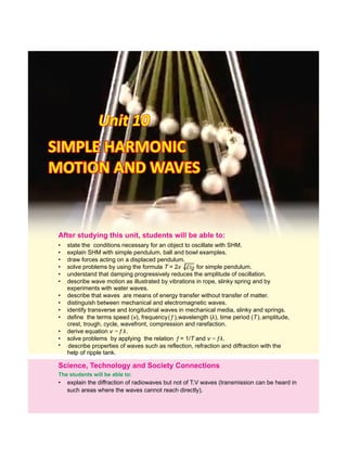
  • 1. Unit 10Unit 10Unit 10 SIMPLE HARMONICSIMPLE HARMONIC MOTION AND WAVESMOTION AND WAVES SIMPLE HARMONIC MOTION AND WAVES • explain the diffraction of radiowaves but not of T.V waves (transmission can be heard in such areas where the waves cannot reach directly). Science, Technology and Society Connections The students will be able to: After studying this unit, students will be able to: • state the conditions necessary for an object to oscillate with SHM. • explain SHM with simple pendulum, ball and bowl examples. • draw forces acting on a displaced pendulum. • solve problems by using the formula T = 2π ll /g for simple pendulum. • understand that damping progressively reduces the amplitude of oscillation. • describe wave motion as illustrated by vibrations in rope, slinky spring and by experiments with water waves. • describe that waves are means of energy transfer without transfer of matter. • distinguish between mechanical and electromagnetic waves. • identify transverse and longitudinal waves in mechanical media, slinky and springs. • define the terms speed (v), frequency( f ),wavelength (λ), time period (T), amplitude, crest, trough, cycle, wavefront, compression and rarefaction. • derive equation v = f λ. • solve problems by applying the relation f = 1/T and v = fλ. • describe properties of waves such as reflection, refraction and diffraction with the help of ripple tank. l g
  • 2. A body is said to be vibrating if it moves back and forth or to and fro about a point. Another term for vibration is oscillation. A special kind of vibratory or oscillatory motion is called the simple harmonic motion (SHM), which is the main focus of this chapter. We will discuss important characteristics of SHM and systems executing SHM. We will also introduce different types of waves and will demonstrate theirpropertieswiththehelpofrippletank. 10.1  SIMPLEHARMONICMOTION(SHM) In the following sections we will discuss simple harmonic motion of different systems. The motion of mass attached to a spring on a horizontal frictionless surface, the motion of a ball placed in a bowl and the motion of a bob attached to a stringareexamplesofSHM. MOTION OF MASS ATTACHED TO A SPRING One of the simplest types of oscillatory motion is that of horizontal mass-spring system (Fig.10.1). If the spring is stretched or compressed through a small displacement x from its mean position, it exerts a force F on the mass. According to Hooke’s law this force is directly proportional to thechangeinlengthxofthespringi.e., ........ (10.1) where x is the displacement of the mass from its mean position O, and k is a constant called the spring constant definedas The value of k is a measure of the stiffness of the spring. Stiff springs have large value of k and soft springs have small value of k. It means that the acceleration of a mass attached to a spring is directly proportional to its displacement from the mean position. Hence, the horizontal motion of a mass-spring systemisanexampleofsimpleharmonicmotion. For your information A spider detects its prey due to vibrationproducedintheweb. 2 SIMPLE HARMONIC MOTION AND WAVES Not For Sale – PESRP As or Fig.10.1: SHM of a mass-spring system a - x ........ (10.2) F = 0 B B O O A A F F (a) (b) x (c) x = 0 x F = - k x k = - F x k = - ma x a = - xk m F = ma x Therefore,
  • 3. SIMPLE HARMONIC MOTION AND WAVES 3 For your information Kinetic and potential energy at different positions in a mass–springsystem. x = -A x = 0 x = +A K.E =0 P.E = max P.E = 0 K.E = max P.E = max K.E = 0 The negative sign in Eq. 10.1 means that the force exerted by the spring is always directed opposite to the displacement of the mass. Because the spring force always acts towards the meanposition,itissometimescalledarestoringforce. Arestoringforcealwayspushesorpullstheobjectperforming oscillatorymotiontowardsthemeanposition. Initially the mass m is at rest in position O and themean resultant force on the mass is zero (Fig.10.1-a). Suppose the mass is pulled through a distance x up to extreme position A and then released (Fig.10.1-b). The restoring force exerted by the spring on the mass will pull it towards the position O. Due to the restoring forcemean the mass moves back, towards the mean position O. The magnitude of the restoring force decreases with the distance from the mean position and becomes zero at O. However, the mass gains speed as it moves towards the mean position and its speed becomes maximum at O. Due to inertia the mass does not stop at the mean position O but continues its motion and reaches the extreme position B. As the mass moves from the position O to the extrememean position B, the restoring force acting on it towards the mean position steadily increases in strength. Hence the speed of themassdecreasesasitmovestowardstheextremeposition B. The mass finally comes briefly to rest at the extreme position B (Fig. 10.1-c). Ultimately the mass returns to the meanpositionduetotherestoringforce. This process is repeated, and the mass continues to oscillate back and forth about the mean position O. Such motion of a mass attached to a spring on a horizontal frictionless surface isknownasSimpleHarmonicMotion(SHM). The time period T of the simple harmonic motion of a mass ‘m’attachedtoaspringisgivenbythefollowingequation: Not For Sale – PESRP ´ m T 2 ......... (10.3) Tidbits A human eardrum can oscillate back and forth up to 20,000 timesinonesecond. Quick Quiz What is the displacement of an objectinSHMwhenthekinetic and potential energies are equal?m k T
  • 4. SIMPLE HARMONIC MOTION AND WAVES BALLANDBOWLSYSTEM The motion of a ball placed in a bowl is another example of simple harmonic motion . When the ball is at the(Fig 10.2) mean position O, that is, at the centre of the bowl, net force acting on the ball is zero. In this position, weight of the ball acts downward and is equal to the upward normal force of the surface of the bowl. Hence there is no motion. Now if we bring the ball to position A and then release it, the ball will start moving towards the mean position O due to the restoring force caused by its weight. At position O the ball gets maximum speed and due to inertia it moves towards the extreme position B. While going towards the position B, the speed of the ball decreases due to the restoring force which acts towards the mean position. At the position B, the ball stops for a while and then again moves towards the mean position O under the action of the restoring force. This to and fro motion of the ball continues about the mean position O till all its energy is lost due to friction. Thus the to and fro motion of the ball about a mean position placed in a bowl is anexampleofsimpleharmonicmotion. MOTIONOFASIMPLEPENDULUM A simple pendulum also exhibits SHM. It consists of a small bob of mass ‘m’ suspended from a light string of length ‘ ’ fixed at its upper end. In the equilibrium position O, the net force on the bob is zero and the bob is stationary. Now if we bring the bob to extreme position A, the net force is not zero (Fig.10.3). There is no force acting along the string as the tension in the string cancels the component of the weight mgcosθ.Hencethereisnomotionalongthisdirection. Thecomponentoftheweightmgsin isdirectedtowardstheθ mean position and acts as a restoring force. Due to this force the bob starts moving towards the mean position O. At O, the bob has got the maximum velocity and due to inertia, it does not stop at O rather it continues to move towards the extreme position B. During its motion towards point B, the velocity of the bob decreases due to restoring force. The velocityofthebobbecomeszeroasitreachesthepointB. 4 Fig. 10.3: Forces acting on a displaced pendulum. The restoring force that causes the pendulum to undergo simple harmonic motion is the component of gravitational force mg sinθ tangent to the pathofmotion Not For Sale – PESRP o mgsinθ mg mgcosθ A TT B θ T S w = mg Mean position m m m l l Fig. 10.2: When a ball is gently displaced from the centre of a bowl it starts oscillating about the centre due to force of gravity which acts as a restoringforce B Ball R A w = mg O Bowl
  • 5. 5 The restoring force mgsin still acts towards the meanθ position O and due to this force the bob again starts moving towards the mean position O. In this way, the bob continues itstoandfromotionaboutthemeanpositionO. It is clear from the above discussion that the speed of the bob increaseswhilemovingfrompointAtoOduetotherestoring force which acts towards O. Therefore, acceleration of the bob is also directed towards O. Similarly, when the bob moves from O to B, its speed decreases due to restoring force which again acts towards O. Therefore, acceleration of the bob is again directed towards O. It follows that the acceleration of the bob is always directed towards the mean positionO.HencethemotionofasimplependulumisSHM. Wehavethefollowingformulaforthetimeperiodofasimple pendulum ......... (10.4) Fromthemotionofthesesimplesystems,wecandefineSHM as: Simple harmonic motion occurs when the net force is directly proportional to the displacement from the mean position and is always directed towards the mean position. In other words, when an object oscillates about a fixed position (mean position) such that its acceleration is directly proportional to its displacement from the mean position and is always directed towards the mean position, its motion is calledSHM. ImportantfeaturesofSHMaresummarizedas: i. A body executing SHM always vibrates about a fixed position. ii. Its acceleration is always directed towards the mean position. iii. The magnitude of acceleration is always directly proportional to its displacement from the mean Time Period Time period of a pendulum is the time to complete one cycle. Check Your Understanding Tell whether or not these motions are examples of simpleharmonicmotion: (a) up and down motion of a leaf in water pond (b) motion of a ceiling fan (c) motion of hands of clock (d) motion of a plucked string fixed at both its ends (e) movement of honey bee. SIMPLE HARMONIC MOTION AND WAVES ß l T 2 Not For Sale – PESRP l g For your information The period of a pendulum is independent of its mass and amplitude. T
  • 6. SIMPLE HARMONIC MOTION AND WAVES position i.e., acceleration will be zero at the mean position while it will be maximum at the extreme positions. iv. Its velocity is maximum at the mean position and zero attheextremepositions. Now we discuss different terms which characterize simple harmonicmotion. Vibration: One complete round trip of a vibrating body about itsmeanpositioniscalledonevibration. Time Period (T ): The time taken by a vibrating body to completeonevibrationiscalledtimeperiod. Frequency ( f ): The number of vibrations or cycles of a vibrating body in one second is called its frequency. It is reciprocaloftimeperiodi.e.,f=1/T Amplitude (A): The maximum displacement of a vibrating body on either side from its mean position is called its amplitude. Example10.1:Findthetimeperiodandfrequencyofasimple -2 pendulum1.0mlongatalocationwhereg=10.0ms . Solution: -2 Given, =1.0m,g=10.0ms . Usingtheformula, Byputtingthevalues =1.99s Frequencyofsimplependulumisgivenby f = 1/T = 1/1.99 s = 0.50 Hz 10.2 DAMPEDOSCILLATIONS Vibratory motion of ideal systems in the absence of any friction or resistance continues indefinitely under the action of a restoring force. Practically, in all systems, the force of friction retards the motion, so the systems do not oscillate indefinitely. The friction reduces the mechanical energy of 6 For your information Christian Huygens invented the pendulum clock in 1656. He was inspired by the work of Galileo who had discovered that all pendulums of the same length took the same amount of time to complete one full swing. Huygens developed the first clock that could accurately measuretime. ß l T 2 g Not For Sale – PESRP 2 sm0.10 m0.1 14.32  T g l l T T m m s
  • 7. SIMPLE HARMONIC MOTION AND WAVES the system as time passes, and the motion is said to be damped. This damping progressively reduces the amplitude ofthevibrationofmotionasshowninFig.10.4. Shockabsorbersinautomobiles areonepracticalapplication of damped motion. A shock absorber consists of a piston moving through a liquid such as oil . The upper part(Fig.10.5) oftheshockabsorberisfirmlyattachedtothebodyofthecar. When the car travels over a bump on the road, the car may vibrate violently. The shock absorbers damp these vibrations andconverttheirenergyintoheatenergyoftheoil.Thus The oscillations of a system in the presence of some resistive forcearedampedoscillations. 10.3 WAVEMOTION Waves play an important role in our daily life. It is because waves are carrier of energy and information over large distances.Wavesrequiresomeoscillatingorvibratingsource. Here we demonstrate the production and propagation of differentwaveswiththehelpofvibratorymotionofobjects. Activity 10.1: Dip one end of a pencil into a tub of water, and move it up and down vertically (Fig. 10.6). The disturbance in the form of ripples produces water waves, which move away fromthesource.Whenthewavereachesasmallpieceofcork floatingnearthedisturbance,itmovesupanddownaboutits original position while the wave will travel outwards. The net displacement of the cork is zero. The cork repeats its vibratorymotionaboutitsmeanposition. Activity 10.2: Take a rope and mark a point P on it. Tie one end of the rope with a support and stretch the rope by holding its other end in your hand (Fig. 10.7). Now, flipping the rope up and down regularly will set up a wave in the rope which will travel towards the fixed end. The point P on the rope will start vibrating up and down as the wave passes across it. The motion of point P will be perpendicular to the directionofthemotionofwave. 7 Fig. 10.5: Shock absorber Attached to car frame Piston Pencil Liquid Attached to car axle Fig. 10.4: The variation of amplitude with time of dampingsystem Displacement o + - Decreasing amplitide “Envelope” of the damping Time Fig. 10.6: Waves produced by dipping a pencil in a water tub Fig. 10.7: Waves produced in a rope Crest Trough P Support P P P Not For Sale – PESRP Cork
  • 8. SIMPLE HARMONIC MOTION AND WAVES Fromtheabovesimpleactivities,wecandefinewaveas: A wave is a disturbance in the medium which causes the particles of the medium to undergo vibratory motion about their mean position in equal intervals of time. Therearetwocategoriesofwaves: 1. Mechanicalwaves 2. Electromagneticwaves Mechanical Waves: Waves which require any medium for theirpropagationarecalledmechanicalwaves. Examples of mechanical waves are water waves, sound wavesandwavesproducedonthestringsandsprings. Electromagnetic Waves: Waves which do not require any medium for their propagation are called electromagnetic waves. Radiowaves, television waves, X-rays, heat and light waves aresomeexamplesofelectromagneticwaves. 10.4 TYPESOFMECHANICALWAVES Depending upon the direction of displacement of medium with respect to the direction of the propagation of wave itself, mechanical waves may be classified as longitudinal or transverse. Longitudinal waves can be produced on a spring (slinky) placed on a smooth floor or a long bench. Fix one end of the slinky with a rigid support and hold the other end into your hand. Now give it a regular push and pull quickly in the directionofitslength(Fig.10.8). 8 For your information Electromagnetic waves consist of electric and magnetic fields oscillating perpendicular to eachother. Direction of wave motion Electric field Magnetic field Quick Quiz Do mechanical waves pass through vacuum, that is, emptyspace? Not For Sale – PESRP
  • 9. SIMPLE HARMONIC MOTION AND WAVES Fig. 10.8: Longitudinal wave on a slinky A series of disturbances in the form of waves will start moving along the length of the slinky. Such a wave consists of regions called compressions, where the loops of the spring are close together, alternating with regions called rarefactions (expansions),wheretheloopsarespacedapart.Intheregionsof compression, particles of the medium are closer together while intheregionsofrarefaction,particlesofthemediumarespaced apart. The distance between two consecutive compressions is called wavelength. The compressions and rarefactions move backandforthalongthedirectionofmotionofthewave.Sucha waveiscalledlongitudinalwaveandisdefinedas: In longitudinal waves the particles of the medium move back andforthalongthedirectionofpropagationofwave. We can produce transverse waves with the help of a slinky. Stretch out a slinky along a smooth floor with one end fixed. Grasp the other end of the slinky and move it up and down quickly (Fig.10.9). A wave in the form of alternate crests and troughs will start travelling towards the fixed end. The crests are the highest points whilethe troughs are the lowest points of the particles of the medium from the mean position. The distance between two consecutive crests or troughs is called 9 For your Information Longitudinal waves move faster through solids than through gases or liquids. Transverse waves move through solids at a speed of less than half of the speed of longitudinal waves. It is because the restoring force exerted during this up and down motion of particles of the medium is less than the restoring force exerted by a back and forth motion of particlesofthemediumincase oflongitudinalwaves. Movement of hand Direction of wave travel Displacement of particles Compression Rarefaction Support Compression Compression Not For Sale – PESRP λ Fig. 10.8: Longitudinal wave on a slinky
  • 10. SIMPLE HARMONIC MOTION AND WAVES wavelength. The crests and troughs move perpendicular to thedirectionofthewave. Fig. 10.9: Transverse wave on a slinky Therefore, transverse waves can be defined as: In case of transverse waves, the vibratory motion of particles of the medium is perpendicular to the direction of propagation of waves. Waves on the surface of water and light waves are examples oftransversewaves. WAVESASCARRIERSOFENERGY Energy can be transferred from one place to another through waves. For example, when we shake the stretched string up and down, we provide our muscular energy to the string. As a result, a set of waves can be seen travelling along the string. Thevibratingforcefromthehanddisturbstheparticlesofthe string and sets them in motion. These particles then transfer their energy to the adjacent particles in the string. Energy is thus transferred from one place of the medium to the other intheformofwave. The amount of energy carried by the wave depends on the distance of the stretched string from its rest position. That is, the energy in a wave depends on the amplitude of the wave. If we shake the string faster, we give more energy per second to produce wave of higher frequency, and the wave delivers more energy per second to the particles of the string as it movesforward. Water waves also transfer energy from one place to another 10Not For Sale – PESRP Crest Movement of hand from side to side Troughs Support Wave movement Particle movement λ
  • 11. SIMPLE HARMONIC MOTION AND WAVES asexplainedbelow: Activity 10.3: Drop a stone into a pond of water. Water waves will be produced on the surface of water and will travel outwards (Fig. 10.10). Place a cork at some distance from the falling stone. When waves reach the cork, it will move up and down alongwith the motion of the water particles by getting energyfromthewaves. Fig. 10.10 Thisactivityshowsthatwaterwaveslikeotherwavestransfer energy from one place to another without transferring matter,i.e.,water. RELATION BETWEEN VELOCITY, FREQUENCY AND WAVELENGTH Wave is a disturbance in a medium which travels from one place to another and hence has a specific velocity of travelling. Thisiscalledthevelocityofwavewhichisdefinedby Velocity=distance/time If time taken by the wave in moving from one point to another is equal to its time period T, then the distance covered by the wavewillbeequaltoonewavelength ,hencewecanwrite:λ ButtimeperiodT,isreciprocalofthefrequencyf,i.e., 11 For your information Generating a high frequency wave, requires more energy per second than to generate a low frequency wave. Thus, a high frequency wave carries more energy than a low frequency wave of the same amplitude. Do you know? Earthquake produces waves through the crust of the Earth in the form of seismic waves. By studying such waves, the geophysicists learn about the internal structure of the Earth and information about the occurrence of future Earth activity. Cork and waterCork and water go up and downgo up and down Cork and water go up and down Energy travelsEnergy travels in this directionin this direction Energy travels in this direction Not For Sale – PESRP f T 1  f v = v = d t T λ T f
  • 12. SIMPLE HARMONIC MOTION AND WAVES Therefore, ......... (10.5) Eq.(10.5)istrueboth longitudinaland transversewaves.for Example 10.2: A wave moves on a slinky with frequency of 4 Hzandwavelengthof0.4m.Whatisthespeedofthewave? Solution: Giventhat, f =4Hz,λ=0.4m Wave speed =(4Hz)(0.4m) -1 v=1.6ms 10.5 RIPPLETANK Ripple tank is a device to produce water waves and to study theircharacteristics. This apparatus consists of a rectangular tray having glass bottom and is placed nearly half metre above the surface of a table (Fig. 10.11). Waves can be produced on the surface of waterpresentinthetraybymeansofavibrator(paddle). Fig. 10.11: Ripple tank apparatus Thisvibratorisanoscillatingelectricmotorfixedonawooden plateoverthetraysuchthatitslowersurfacejusttouchesthe surface of water. On setting the vibrator ON, this wooden plate starts vibrating to generate water waves consisting of straight wavefronts (Fig.10.12). An electric bulb is hung above the tray to observe the image of water waves on the paper or screen. The crests and troughs of the waves appear asbrightanddarklinesrespectively,onthescreen. Nowweexplainthereflectionofwaterwaveswiththehelpof rippletank. 12 Lamp Shallow tank of water Oscillating paddle Power supply Wave patterns on a viewing screen Fig. 10.12: Waves consisting of straightwavefronts Not For Sale – PESRP v = f v = f λ λ λ
  • 13. λ v v λ 2 2 1 1 SIMPLE HARMONIC MOTION AND WAVES 13 Place a barrier in the ripple tank. The water waves will reflect from the . If the is placed at an angle to thebarrier barrier wavefront,thereflectedwavescanbeseentoobeythelawof reflection i.e., the angle of the incident wave along the normal will be equal to the angle of the reflected wave (Fig.10.13).Thus,wedefinereflectionofwavesas: When waves moving in one medium fall on the surface of another medium they bounce back into the first medium such thattheangleofincidenceisequaltotheangleofreflection. The speed of a wave in water depends on the depth of water. If a block is submerged in the ripple tank, the depth of water in the tank will be shallower over the block than elsewhere. When water waves enter the region of shallow water their wavelength decreases ( . But the frequency of theFig.10.14) water waves remains the same in both parts of water becauseitisequaltothefrequencyofthevibrator. Fig. 10.14 For the observation of refraction of water waves, we repeat the above experiment such that the boundary between the deep and the shallower water is at some angle to the wavefront (Fig. 10.15). Now we will observe that in addition to the change in wavelength, the waves change their direction of propagation as well. Note that the direction of propagation is always normal to the wavefronts. This change of path of water waves while passing from a region of deep water to that of shallower one is called refraction which is defined as: Fig. 10.15: Refraction of water waves Boundary between deep and shallow water Straight wave generator Shallow water (slow speed) Wavefront Deep water (faster speed) Ripple tank Fig. 10.13: Reflection of water wavesfromaplanebarrier Quick Quiz What do the dark and bright fringes on the screen of ripple tankrepresent? Not For Sale – PESRP Incident waves Angle of incidence Normal (a) Barrier (b) Normal Angle of reflection Barrier Reflected waves i r i i r r
  • 14. SIMPLE HARMONIC MOTION AND WAVES When a wave from one medium enters into the second mediumatsomeangle,itsdirectionoftravelchanges. Now we observe the phenomenon of diffraction of water waves. Generatestraightwavesinarippletankandplacetwoobstaclesin line in such a way that separation between them is equal to the wavelength of water waves. After passing through a small slit between the two obstacles, the waves will spread in every directionandchangeintoalmostsemicircularpattern(Fig.10.16). Diffraction of waves can only be observed clearly if the size of the obstacle is comparable with the wavelength of the wave. Fig.10.17showsthediffractionofwaveswhilepassingthrough a slit with size larger than the wavelength of the wave. Only a smalldiffractionoccursnearthecornersoftheobstacle. Thebendingorspreadingofwavesaroundthesharpedgesor cornersofobstaclesorslitsiscalleddiffraction. Example 10.3: A student performs an experiment with waves in water. The student measures the wavelength of a wave to be 10 cm. By using a stopwatch and observing the oscillations of a floating ball, the student measures a frequency of 2 Hz. If the student starts a wave in one part of a tank of water, how long will it take the wave to reach the opposite side of the tank2maway? Solution: (1) Wearegiventhefrequency,wavelength,anddistance. (2) We have to calculate the time, the wave takes to move a distanceof2m. (3) Therelationshipbetweenfrequency,wavelength,andspeedis v = f λ. The relationship between time, speed, and distance is v =d/t (4) Rearrangethespeedformulatosolveforthetime:t=d/v Thespeedofthewaveisthefrequencytimesthewavelength. -1 v=fλ=(2Hz)(0.1m)=0.2ms . Usethisvaluetocalculatethetime: -1 t =2m/0.2ms =10s 14 Fig.10.17: Diffraction of water wavesthroughalargeslit Deep Shallow ACTIVITY Study Fig. 10.18 to answer the followingquestions: 1. What happens to the direction of wave when water waves pass from deep to shallowpartofthewater? 2. Arethemagnitudesofangle of incidence and angle of refractionequal? 3.Whichwillbegreater? Not For Sale – PESRP Fig.10.18 Fig.10.16: Diffraction of water wavesthroughasmallslit
  • 15. SIMPLE HARMONIC MOTION AND WAVES 15 SUMMARY  Simple harmonic motion (SHM) is a to and fro oscillatory motion in which acceleration of the body is directly proportional to the displacement of the body from the mean position and is always directed towards the mean position.  Themotionofamassattachedtoaspring, simplependulumandthatofaballinside abowlisSHM.  Timetakenbythesimplependulumtocompleteonecycleiscalleditstimeperiod.It depends upon the length of the pendulum and is independent of the mass and amplitudeofthependulum.  The number of cycles completed in one second is called frequency of a vibrating body.Itisreciprocaloftimeperiod.  ThemaximumdisplacementfrommeanpositionofabodyperformingSHMiscalled amplitude.  Wave is a phenomenon of transferring energy from one place to another without thetransferofmatter.  Mechanical waves are those waves which require some medium for their propagation.  Electromagneticwavesdonotrequireanymediumfortheirpropagation.  Transverse waves are the mechanical waves in which particles of the medium vibrate about their mean position perpendicular to the direction of propagation of thewaves.  Compressional (longitudinal) waves are the mechanical waves in which particles of the medium vibrate about their mean position along the direction of propagation of thewaves.  The speed (v) of a wave is equal to the product of frequency(f)and wavelength (λ) i.e.,v=fλ.  Ripple tank is a device used to produce water waves and to demonstrate different propertiesofwaterwaveslikereflection,refractionanddiffraction.  When a wave travelling from one medium falls on the surface of another medium, it may bounce back into the first medium. This phenomenon is called reflection of waves.  When waves from one medium enter the second medium at some angle their direction of travel may change. This phenomenon is called refraction of waves. The speed and wavelength of wave change in different media but frequency does not change.  Thebendingofwavesaroundobstaclesorsharpedgesiscalleddiffractionofwaves. Not For Sale – PESRP
  • 16. SIMPLE HARMONIC MOTION AND WAVES 16 MULTIPLE CHOICE QUESTIONS Choose the correct answer from the following choices: i. Which of the following is an example of simple harmonic motion? (a) the motion of simple pendulum (b) the motion of ceiling fan (c) the spinning of the Earth on its axis (d) a bouncing ball on a floor ii. If the mass of the bob of a pendulum is increased by a factor of 3, the period of the pendulum'smotionwill (a) be increased by a factor of 2 (b) remain the same (c) be decreased by a factor of 2 (d) be decreased by a factor of 4 iii. Which of the following devices can be used to produce both transverse and longitudinalwaves? (a)astring (b)arippletank (c) a helical spring (slinky) (d) a tuning fork iv. Waves transfer (a) energy (b) frequency (c) wavelength (d) velocity v. Which of the following is a method of energy transfer? (a) conduction (b) radiation (c) wave motion (d) all of these vi. In a vacuum, all electromagnetic waves have the same (a) speed (b) frequency (c) amplitude (d) wavelength vii. Alargerippletankwithavibratorworkingatafrequencyof30Hzproduces 25 completewavesinadistanceof50cm.Thevelocityofthewaveis -1 (a) 53 cm s (b) -1 60 cm s -1 -1 (c) 750 cm s (d) 1500 cm s viii.Whichofthefollowingcharacteristicsofawaveisindependentoftheothers? (a) speed (b) frequency (c) amplitude (d) wavelength ix. The relation between v, f and λ of a wave is (a) v f = λ (b) f λ = v (c) v λ = f (d) v = λ / f Not For Sale – PESRP
  • 17. SIMPLE HARMONIC MOTION AND WAVES 17 REVIEW QUESTIONS 10.1. What is simple harmonic motion? What are the necessary conditions for a body to executesimpleharmonicmotion? 10.2. Think of several examples of motion in everyday life that are simple harmonic. 10.3. What are damped oscillations. How damping progressively reduces the amplitude ofoscillation? 10.4. How can you define the term wave? Elaborate the difference between mechanical andelectromagneticwaves.Giveexamplesofeach. 10.5. Distinguishbetweenlongitudinalandtransversewaveswithsuitableexamples. 10.6. Draw a transverse wave with an amplitude of 2 cm and a wavelength of 4 cm. Label a crestandtroughonthewave. 10.7. Derivearelationshipbetweenvelocity,frequencyandwavelengthofawave.Writea formularelating ofawavetoitstimeperiodandwavelength.velocity 10.8. Waves are the means of energy transfer without transfer of matter. Justify this statementwiththehelpofasimpleexperiment. 10.9. Explain the following properties of waves with reference to ripple tank experiment: a. Reflection b. Refraction c. Diffraction 10.10. Does increasing the frequency of a wave also increase its wavelength? If not, how arethesequantitiesrelated? CONCEPTUAL QUESTIONS 10.1. Ifthelengthofasimplependulumisdoubled,whatwillbethechangeinitstimeperiod? 10.2. A ball is dropped from a certain height onto the floor and keeps bouncing. Is the motionoftheballsimpleharmonic?Explain. 10.3. A student performed two experiments with a simple pendulum. He/She used two bobs of different masses by keeping other parameters constant. To his/her astonishment the time period of the pendulum did not change! Why? 10.4. Whattypesofwavesdonotrequireanymaterialmediumfortheirpropagation? 10.5. Plane waves in the ripple tank undergo refraction when they move from deep to shallowwater.Whatchangeoccursinthespeedofthewaves? NUMERICAL PROBLEMS 10.1. The time period of a simple pendulum is 2 s. What will be its length on the Earth? -2 WhatwillbeitslengthontheMoonifg =g /6?whereg =10ms .em e Ans.(1.02 m, 0.17 m) 10.2. Apendulumoflength0.99mistakentotheMoonbyanastronaut.Theperiodofthe pendulumis4.9s.WhatisthevalueofgonthesurfaceoftheMoon? Not For Sale – PESRP
  • 18. SIMPLE HARMONIC MOTION AND WAVES 18 Ans. -2 (1.63 m s ) 10.3. Find the time periods of a simple pendulum of 1 metre length, placed on Earth and th on Moon. The value of g on the surface of Moon is 1/6 of its value on Earth, -2 where g is10ms .e Ans.(2 s, 4.9 s) 10.4. A simple pendulum completes one vibration in two seconds. Calculate its length, -2 wheng=10.0ms . Ans.(1.02m) 10.5. If 100 waves pass through a point of a medium in 20 seconds, what is the frequency and the time period of the wave? If its wavelength is 6 cm, calculate the wavespeed. -1 5 Hz, 0.2 s, 0.3 m s )Ans. ( 10.6. A wooden bar vibrating into the water surface in a ripple tank has a frequency of 12 Hz. The resulting wave has a wavelength of 3 cm. What is the speed of the wave? Ans. -1 (0.36 m s ) 10.7. A transverse wave produced on a spring has a frequency of 190 Hz and travels along thelengthofthespringof90m,in0.5s. (a) Whatistheperiodofthewave? (b) Whatisthespeedofthewave? (c) Whatisthewavelengthofthewave? -1 Ans. (0.01 s, 180 m s , 0.95 m) 10.8. Water waves in a shallowdish are 6.0 cm long. At one point, the water moves up and downatarateof4.8oscillationspersecond. (a) Whatisthespeedofthewaterwaves? (b) Whatistheperiodofthewaterwaves? Ans. -1 (0.29 m s , 0.21 s) 10.9. At one end of a ripple tank 80 cm across, a 5 Hz vibrator produces waves whose wavelengthis40mm.Findthetimethewavesneedtocrossthetank. Ans. (4 s) 10.10. What is the wavelength of the radiowaves transmitted by an FM station at 90 MHz? 6 8 -1 where1M=10 ,andspeedofradiowaveis3x10 ms . Ans.(3.33 m) Not For Sale – PESRP
  • 19. Unit 11Unit 11Unit 11 SOUNDSOUNDSOUND The students will be able to: • • • • describe that some sounds are injurious to health. describe how knowledge of the properties of sound waves is applied in the design of building with respect to acoustics. Science, Technology and Society Connections describe how ultrasound techniques are used in medical and industry. explain the use of soft materials to reduce echo sounding in classroom studies, and other public gathering buildings. • explain how sound is produced by vibrating sources and that sound waves require a material medium for their propagation. • describe the longitudinal nature of sound waves (as a series of compressions and rarefactions). • define the terms pitch, loudness and quality of sound. • describe the effect of change in amplitude on loudness and the effect of change in frequency on pitch of sound. • define intensity and state its SI unit. • describe what is meant by intensity level and give its unit. • explain that noise is a nuisance. • describe how reflection of sound may produce echo. • describe audible frequency range. • describe the importance of acoustic protection. • solve problems based on mathematical relations learnt in this unit. After this students will be able to:studying unit,
  • 20. SOUND We know that vibrations of objects in any medium produce waves. For example, vibrator of ripple tank produces water waves. The medium in this case is liquid, but it can also be a gas or a solid. Now we will discuss another type of waves that wecanheari.e.,soundwaves. 11.1 SOUNDWAVES Like other waves, sound is also produced by vibrating bodies. Due to vibrations of bodies the air around them also vibrates and the air vibrations produce sensation of sound in our ear. For example, in a guitar, sound is produced due to the vibrations of its strings (Fig. 11.1). Our voice results from the vibrations of our vocal chords. Human heart beats and vibrations of other organs like lungs also produce sound waves.Doctorsusestethoscopetohearthissound. Fig. 11.1: Vibrations of guitar strings produce sound waves SOUNDISPRODUCEDBYAVIBRATINGBODY Activity 11.1: In school laboratories, we use a device called tuning fork to produce a particular sound. If we strike the tuning fork against rubber hammer, the tuning fork will begin to vibrate (Fig. 11.2). We can hear the sound produced by tuning fork by bringing it near our ear. We can also feel the vibrations by slightly touching one of the prongs of the vibrating tuning fork with a plastic ball suspended from a thread (Fig. 11.3). Touch For your information Stethoscopes operate on the transmission of sound from the chest-piece, via air-filled hollow tubes, to the listener's ears. The chest-piece usually consists of a plastic disc called diaphragm. If the diaphragm is placed on the patient’s body sounds vibrate the diaphragm, creating acoustic pressure waves which after multiple reflection travel up the tubing tothedoctor'sears. 20 Sound waves Strings Ear Guitar Physics of Sound All sounds are produced by the vibrations of objects. Sound is a form of energy that travels in the form of waves from one placetoanother. Fig. 11.2: Strike a rubber hammer on a tuning fork Rubber hammer Tuning fork Not For Sale – PESRP
  • 21. SOUND the ball gently with the prong of a vibrating tuning fork. The tuning fork will push the ball because of its vibrations. Now if we dip the vibrating tuning fork into a glass of water, we will see a splash (Fig. 11.4). What does make the water splash? From this activity, we can conclude that sound is produced by vibratingbodies. SoundRequiresMaterialMediumforitsPropagation Activity 11.2: Unlike light waves which are electromagnetic in nature and can also pass through vacuum, sound waves require some material medium for their propagation. This can be proved by bell jar apparatus (Fig. 11.5). The bell jar is placed on the platform of a vacuum pump. An electric bell is suspended in the bell jar with the help of two wires connected to a power supply. By setting ON the power supply, electric bell will begin to ring. We can hear the sound of the bell. Now start pumping out air from the jar by means of a vacuum pump. The sound of the bell starts becoming more and more feeble and eventually dies out, although bell is still ringing. When we put the air back into the jar, we can hear the sound of the bell again. From this activity, we conclude that sound waves can only travel/propagate in the presence of air (medium). LongitudinalNatureofSoundWaves Propagation of sound waves produced by vibrating tuning fork can be understood by a vibrating tuning fork as shown in Fig.11.6. Before the vibration of tuning fork, density of air molecules on the right side is uniform (Fig.11.6-a). When the right prong of tuning fork moves from mean position O to B (Fig.11.6-b), it exerts some pressure on the adjacent layer of air molecules and produces a compression. Fig. 11.4 Fig. 11.3: The production of sound waves from a vibrating tuning fork Fig. 11.5: Bell jar apparatus 21 Power supply Bell jar Electric bell Vacuum pump (a) (b) (c) Fig.11.6: Vibrations of tuning fork after striking with a rubber Thread Vibrating tuning fork Table tennis ball Vibrating tuning fork Glass Water A O B O B A O Not For Sale – PESRP
  • 22. SOUND This compressed air layer in turn compresses the layer next to it and so on. A moment later, the prong begins to move from B towards A (Fig.11.6-c). Now the pressure in the adjacent layer decreases and a rarefaction is produced. This rarefaction is transfered to the air layer next to it and so on. As the tuning fork moves back and forth rapidly, a series of compressions and rarefactions are created in the air. In this way, sound wave propagates through the air. Asinthe thedirectionof propagation of sound waveFig.11.6, is along the direction of oscillating air molecules. This shows the longitudinal nature of sound waves. Distance between two consecutive compressions or rarefactions is the wavelengthofsoundwave. 11.2  CHARACTERISTICSOFSOUND Sounds of different objects can be distinguished on the basis ofdifferentcharacteristicsasdescribedbelow: Loudness: Loudness is the characteristic of sound by which loudandfaintsoundscanbedistinguished. When we talk to our friends, our voice is low, but when we address a public gathering our voice is loud. Loudness of a sound depends upon a number of factors. Some of them are discussedbelow: (a) Amplitude of the vibrating body: The loudness of the sound varies directly with the amplitude of the vibrating body (Fig.11.7). The sound produced by a sitar will be loud if we pluck its wires more violently. Similarly, when we beat a drum forcefully, the amplitude of its membrane increases and we hear a loudsound. (b) Area of the vibrating body: The loudness of sound also depends upon the area of the vibrating body. 22 Fig. 11.7: Variation of loudness withamplitude Quick Quiz Identify which part of these musical instruments vibrates toproducesound: (a) electric bell (b) loud speaker (c) piano (d) violin (e)flute. Self Assessment 1. Explain how sound is producedbyaschoolbell. 2. Why are sound waves called mechanicalwaves? 3.Suppose you and your friend are on the Moon. Will you be able to hear any sound producedbyyourfriend? Large amplitude Loud Quiet Small amplitude Not For Sale – PESRP Physics Insight Illustration of longitudinal wave formed by vibrating tuning fork in the air. Compressions are places where air pressure is slightly higher than the surrounding air pressure due to high density of air particles. While rarefactions are the regions correspond to low air pressure due to low density of air particles.
  • 23. SOUND For your information Thin-walled glass goblets can vibrate when hit by sound waves. This is due to a phenomenon of sound known as resonance. Some singers can produce a loud note of particular frequency such that it vibrates the glass so much thatitshatters. Interesting information Some people use silent whistle to call dogs whose frequency lies between 20,000 Hz to 25,000 Hz. It is silent for human but not for dogs because the audible frequency rangefordogsismuchhigher. 23 For example, sound produced by a large drum is louder than that by small one because of its large vibrating area. If we strike a tuning fork on a rubber pad, a feeble sound will be heard. But if the vibrating tuning fork is placed vertically on the surface of a bench, we will hear a louder sound. From this, we can conclude that the loudness increases with the area of thevibratingbodyandviceversa. (c) Distance from the vibrating body: Loudness of sound also depends upon the distance of the vibrating body from the listener. It is caused by the decrease in amplitudeduetoincreaseindistance. Loudness also depends upon the physical condition of the ears of the listener. A sound appears louder to a person with sensitive ears than to a person with defective ears. However, there is a characteristic of sound which does not depend upon the sensitivity of theearofthelisteneranditiscalledintensityofsound. Pitch: Pitch is the characteristic of sound by which we can distinguishbetweenashrillandagravesound. It depends upon the frequency. A higher pitch means a higher frequency and vice versa. The frequency of the voice of ladies and children ishigherthan thatofmen.Therefore,thevoiceof ladies and children is shrill and of high pitch. The relationship betweenfrequencyandpitchisillustratedinFig.11.8. Quality: The characteristic of sound by which we can distinguish between two sounds of same loudness and pitch iscalledquality. While standing outside a room, we can distinguish between the notes of a piano and a flute being played inside the room. Thisisduetothedifferenceinthequalityofthesenotes. Figure 11.9 shows the waveform of the sound produced by a tuning fork, flute and clarinet. The loudness and the pitch of Fig11.8:Variationofpitchwith frequency Low frequency Low pitch High pitch High frequency For your information Fig 11.9: Sound waveforms produced by (a) a tuning fork, (b) a flute, and (c) a clarinet, are all at approximately the same frequency. Pressure is plotted vertically, time (a) (b) (c) Tuning fork Flute Clarinet Not For Sale – PESRP
  • 24. SOUND these three sounds are the same but their waveforms are different. So their quality is different and they can be distinguishedfromeachother. Intensity The sound waves transfer energy from the sounding body to thelistener.Theintensityofsounddependsontheamplitude ofsoundwaveandisdefinedas: Sound energy passing per second through a unit area held perpendicular to the direction of propagation of sound wavesiscalledintensityofsound. Intensity is a physical quantity and can be measured accurately. The unit of intensity of sound is watt per square metre(W ). -2 m SoundIntensityLevel The human ear responds to the intensities ranging from -12 -2 10 W m to more than 1 W m (which is loud enough to be -2 painful). Because the range is so wide, intensities are scaled by factors of ten. The barely audible and the faintest intensity -12 of sound i.e., 10 W m is taken as reference intensity, called -2 zerobel(aunitnamedafterAlexanderGrahamBell). The loudness of a sound depends not only on the intensity of sound but also on the physical conditions of the ear. The human ear is more sensitive to some frequencies rather than the others. The loudness (L) of a sound is directly proportional to the logarithmofintensityi.e., L logI L=Klog .......... (11.1)I whereKisaconstantofproportionality. Let L be the loudness of the faintest audible sound of intensityo I Iand L be the loudness of an unknown sound of intensity ,o thenbyEq.(11.1),wecanwrite L = K log (11.2)I ..........o o SubtractingEq.(11.2)fromEq.(11.1),weget 24 Do you know? Frequency of tuning fork depends on the mass of its prongs. The greater the mass, the lower the frequency of vibration which means the lowerthepitch. Quick Quiz 1. Why the voice of women is more shrill than that of men? 2. Which property of sound wavedeterminesits: (a)loudness (b)pitch? 3. What would happen to the loudness of sound with increase in its frequency? Not For Sale – PESRP For your information Asoundwavewithafrequency of 3500 Hz and an intensity of 80 dB sounds about twice as loud to us as a sound of 125 Hz and 80 dB. It is because our ears are more sensitive to the 3500 Hz sound than to the 125 Hz. Therefore intensity by itself does not mean loudness. Loudness is how our ears detect and our brain perceives theintensityofsoundwaves.
  • 25. SOUND L - L = K (log - log ) = K logI Io o Thisdifference,(L-L ),betweentheloudnessLofanunknowno sound and the loudness L is called the intensity level of theo unknown sound. Therefore, the intensity level of an unknownsoundisgivenby Intensity level = K log .......... (11.3) The value of K depends not only on the units of and butI Io also on the unit of intensity level. If intensity of anyI unknown sound is 10 times greater than the intensity ofIo the faintest audible sound i.e., =10 and the intensity levelI Io of such a sound is taken as unit, called bel, the value of K becomes1.Therefore,usingK=1,Eq.(11.3)becomes Intensity .......... (11.4)level = log (bel) bel is a very large unit of intensity level of a sound. Generally, a smaller unit called decibel is used. Decibel is abbreviated as (dB).Itmustberememberedthat1belisequalto10dB.Ifthe intensitylevelismeasuredindecibels,Eq.(11.4)becomes Intensity .......... (11.5)level = 10 log (dB) Using Eq. (11.5), we can construct a scale for measuring the intensity level of sound. Such scale is known as “decibel scale”. The intensity level of different sounds in decibel is giveninTable11.1. Example 11.1: Calculate the intensity levels of the (a) faintest audiblesound(b)rustlingofleaves. Solution: (a) Intensity level of faintest audible sound can be -12 -2 calculated by substituting = 10 Wm in Eq. (11.5).oI I = Therefore, Intensityleveloffaintest sound=10log dBaudible =0dB -11 -2 (b) As the intensity of the rustle of leaves is =10 W m ,I 25 Sources of Sound Nearby jet airplane Jackhamm- er/Fast train Siren Lawn mover Vacuum cleaner Mosquito buzzing Whisper Rustling of leaves Faintest audible sound i.e., Threshold Intensity (Wm ) -2 3 10 1 10 0 10 -2 10 -5 10 -8 10 -9 10 -11 10 -12 10 Intensity level (dB) 150 130 120 100 70 40 30 10 0 Table 11.1 Not For Sale – PESRP For your information The decibel scale is a logarithmic measure of the amplitude of sound waves. In a logarithmic scale, equal intervals correspond to multiplying by 10 instead of addingequalamounts. Decibels (dB) Amplitude (m) 0 20 40 60 80 100 120 1 10 100 1,000 10,000 1000,000 1,000,000 Logarithmic scale Linear scale I Io 10 -12 10 -12 I Io I Io I Io
  • 26. SOUND therefore, -11 -12 Intensitylevelduetorustlingofleaves=10log10 /10 dB =10log10dB =10dB 11.3 REFLECTION(ECHO)OFSOUND When we clap or shout near a reflecting surface such as a tall building or a mountain, we hear the same sound again a little later. What causes this? This sound which we hear is called anechoandisaresultofreflectionofsoundfromthesurface. When sound is incident on the surface of a medium it bounces back into the first medium. This phenomenon is calledechoorreflectionofsound. The sensation of sound persists in our brain for about 0.1 s. To hear a clear echo, the time interval between our sound and the reflected sound must be at least 0.1 s. If we consider -1 speed of sound to be 340 ms at a normal temperature in air, we will hear the echo after 0.1 s. The total distance covered by the sound from the point of generation to the reflecting -1 surface and back should be at least 340 m s × 0.1 s = 34.0 m. Thus, for hearing distinct echoes, the minimum distance of the obstacle from the source of sound must be half of this distance,i.e.,17m.Echoesmaybeheardmorethanoncedue tosuccessiveormultiplereflections. Activity 11.3: Take two identical plastic pipes of suitable length, as shown in Fig. 11.10. (We can make the pipes using chartpaper).  Arrangethepipesonatablenearawall.  Place a clock near the open end of one of the pipes and trytohearthesoundoftheclockthroughtheotherpipe.  Adjust the position of the pipes so that you can hear thesoundoftheclockclearly.  Now, measure the angles of incidence and reflection andseetherelationshipbetweentheangles. 26 Do you know? Elephants use low frequency sound waves to communicate with one another. Their large ears enable them to detect these low frequency sound waves, which have relatively long wavelengths. Elephants caneffectivelycommunicatein this way, even when they are separatedbymanykilometres. Interesting information A blue whale's 180 dB rumble is the loudest animal sound ever recorded. Whale sounds also appear to be a part of a highly evolved communication system. Some whales are thought to communicateoverhundredsand may be thousands of kilometres. This is possible, in part, because sound waves travel five times faster in water than in air. In addition, the temperature characteristics of ocean water — decrease in temperature with depth — create a unique sound phenomenon. Not For Sale – PESRP
  • 27. SOUND  Lift the pipe on the right vertically to a small height andobservewhathappens. Fig. 11.10: Reflection of sound 11.4 SPEED OF SOUND Sound waves can be transmitted by any medium containing particles that can vibrate. They cannot pass through vacuum. However, the nature of the medium will affect the speed of the sound waves. In general, the speed of sound in a liquid is five times that in gases; the speed of sound in solid is about fifteen times that in gases. The speed of sound in air is affected by changes in some physical conditions such as temperature,pressureandhumidityetc. -1 The speed of sound in air is 343 m s at one atmosphere of pressure and room temperature (21°C). The speed varies with temperature and humidity. The speed of sound in solids andliquidsisfasterthaninair. Followingrelationcanbeused tofindthespeedofsound: v = f λ ........ (11.6) where v is the speed, f is the frequency and is theλ wavelengthofsoundwave. Example 11.2: Calculate the frequency of a sound wave of -1 speed340ms andwavelength0.5m. Solution:Giventhat; -1 speedofwaves v=340ms 27 For your information By using an oscilloscope, you can“see”soundwaves. Wave on screen Microphone OscilloscopeAmplifier Not For Sale – PESRP Angle of reflection Pipe Screen Wall Table Ear r Clock Angle of incidence i Table 11.1 Speed of sound in various media Medium Speed (m s ) -1 Gases o Air(0 C) 331 0 Air (25 C) 346 o Air(100 C) 386 o Hydrogen (0 C) 1290 o Oxygen (0 C) 317 o Helium (0 C) 972 0 Liquids at 25 C Distilled water 1498 Sea water 1531 0 Solids 25 C Wood 2000 Aluminium 6420 Brass 4700 Nickel 6040 Iron 5950 Steel 5960 Flint Glass 3980
  • 28. SOUND Wavelength λ=0.5m Usingtheformula v= λf Puttingthevalues =340 /0.5m=680Hz -1 f ms MeasuringSpeedofSoundbyEchoMethod Apparatus: Measuring tape, stopwatch, flat wall that can produceagoodecho. Procedure: 1. Use the tape to measure a distance of 50 metres from thewall. 2. Now clap your hands in front of the wall at a distance of 50 metres and check if you can clearly hear anecho from the wall. Make sure the echo is not comingfrom any other wall in the area. The time taken by the sound to travel 100 metres is the time difference betweentheclapandtheecho. 3. Now restart the clapping and start the stopwatch at the first clap. Count the number of claps, and stopthe clapping and the stopwatch when you hear theecho ofthe10thclap(say). 4. Now find the average time for 10 claps. After calculating the time interval t between claps and using the formula S = vt, we can calculate the speedof thesound. Example 11.3: Flash of lightning is seen 1.5 seconds earlier than the thunder. Howfar away is the cloud in which the flash -1 hasoccurred?(speedofsound=332ms ). Solution: -1 Given that, time t = 1.5 s, speed of sound v = 332 m s . -1 Therefore,distanceofthecloud S = vt =1.5s×332ms =498 m. 11.5  NOISE POLLUTION We enjoy the programmes on radio or television by hearing sounds of different qualities. In musical programmes, we hear sound produced by musical instruments such as flute, harmonium, violin, drum etc. Sound of these instruments has pleasant effect on our ears. Such sounds which are pleasant to 28Not For Sale – PESRP A B Do you know? The speed of sound in air was first accurately measured in 1738bymembersoftheFrench Academy. Two cannons were s e t u p o n t w o h i l l s approximately 29 km apart. By measuring the time interval between the flash of a cannon and the “boom”, the speed of sound was calculated. Two c a n n o n s w e r e f i r e d alternatively to minimize errors due to the wind and to delayed reactions in the observers. From their observations, they deduced that sound travels at 0 about336ms at0 C. -1
  • 29. SOUND our ears are called musical sounds. However, some sounds produce unpleasant effects on our ears such as sound of machinery, the slamming of a door, and sounds of traffic in big cities. Sound which has jarring and unpleasant effect on our ears is called noise. Noise corresponds to irregular and sudden vibrationsproducedbysomesounds. Noise pollution has become a major issue of concern in big cities.Noiseisanundesirablesoundthatisharmfulforhealth of human and other species. Transportation equipment and heavy machinery are the main sources of noise pollution. For example, noise of machinery in industrial areas, loud vehicle horns, hooters and alarms. Noise has negative effects on human health as it can cause conditions such as hearing loss, sleep disturbances, aggression, hypertension, high stress levels. Noise can also cause accidents by interfering with communicationandwarningsignals. A safe level of noise depends on two factors: the level (volume) of the noise; and the period of exposure to the noise. The level of noise recommended in most countries is usually 85-90 dB over an eight-hour workday. Noise pollution can be reduced to acceptable level by replacing the noisy machinery with environment friendly machinery and equipments, putting sound-reducing barriers, or using hearingprotectiondevices. Activity 11.4: Develop an action plan to help you address any problem(s) with noise in your workplace considering the followingpoints: 1. Describetheproblem(s). 2. Whatarethesourcesoftheproblem(s)? 3. Whoarethepeoplebeingaffected? 4. Yoursuggestionsforthesolution. 11.6 IMPORTANCE OF ACOUSTICS The technique or method used to absorb undesirable sounds bysoftandporoussurfacesiscalledacousticprotection. Reflection of sound is more prominent if the surface is rigid and smooth, and less if the surface is soft and irregular. Soft, 29 Not For Sale – PESRP Physics insight Sound displays all the properties of waves when it interacts with materials and boundaries. Reflection Refraction Diffraction Absorption
  • 30. SOUND For your information The phrase “blind as a bat” is a false statement. Bats have some vision using light, but when placed in pitch-black rooms crisscrossedwithfinewires,they can easily fly around and unerringly locate tiny flying insects for food. We usually assume that vision requires light but both bats and dolphins have the ability to “see” using sound waves. Research in science and technology has developed “eyes” that enable humans also toseeusingsoundwaves. porous materials, such as draperies and rugs absorb large amountofsoundenergyandthusquietechoesandsoftening noises. Thus by using such material in noisy places we can reduce the level of noise pollution. However, if the surface of classrooms or public halls are too absorbent, the sound level may be low for the audience. Sometimes, when sound reflects from the walls, ceiling, and floor of a room, the reflecting surfaces are too reflective and the sound becomes garbled. This is due to multiple reflections called reverberations. In the design of lecture halls, auditorium, or theater halls, a balance must be achieved between reverberation and absorption. It is often advantageous to place reflective surfaces behind the stage to direct sound to theaudience. Generally, the ceilings of lecture halls, conference halls and theatre halls are curved so that sound after reflection may reach all the corners of the hall (Fig 11.11). Sometimes curved sound boards are placed behind the stage so that sound after reflection distributed evenly across the hall (Fig.11.12). 11.7  AUDIBLE FREQUENCY RANGE We know that sound is produced by a vibrating body. A normal human ear can hear a sound only if its frequency lies between 20Hz and 20,000 Hz. In other words, a human ear neither hears a sound of frequency less than 20 Hz nor a sound of frequency more than 20,000 Hz. Different people have different range of audibility. It also decreases with age. Young children can hear sounds of 20, 000 Hz but old people cannothearsoundsevenabove15,000Hz. 30 Soundboard Bat Prey Source of sound Not For Sale – PESRP For your information P i l o t s w e a r s p e c i a l headphones that reduce the roar of an airplane engine to a quiethum. Fig. 11.11: Curved ceiling of a conference hall Fig. 11.12: Soundboard used in a big hall
  • 31. SOUND The range of the frequencies which a human ear can hear is calledtheaudiblefrequencyrange. 11.8 ULTRASOUND  Sounds of frequency higher than 20, 000 Hz which are inaudible to normal human ear are called ultrasound or ultrasonics. Uses of Ultrasound   Ultrasonic waves carry more energy and higher frequency than audible sound waves. Therefore, accordingtothewaveequationv=f λ,thewavelength of ultrasonic waves is very small and is very useful for detectingverysmallobjects.   Ultrasonicsareutilizedinmedicalandtechnicalfields.   In medical field, ultrasonic waves are used to diagnose and treat different ailments. For diagnosis of different diseases, ultrasonic waves aremadeto enter the human body through transmitters.These waves are reflected differently bydifferentorgans, tissues or tumors etc. The reflectedwavesarethen amplified to form an imageoftheinternalorgansof the body on the screen(Fig.11.13).Suchanimage h e l p s i n detectingthedefectsintheseorgans.   Powerful ultrasound is now being used to remove bloodclotsformedinthearteries.   Ultrasound can also be used to get the pictures of thyroidglandfordiagnosispurposes.   Ultrasound is used to locate underwater depths or is used for locating objects lying deep on the ocean floor, etc. The technique is called SONAR, (sound navigationandranging).Thesoundwavesare sent from a transmitter, and a receiver collects the reflected sound (Fig.11.14). The time-lapse is calculated, knowing the speed of soundinwater,the distance of the object from the oceansurfacecanbe estimated. 31 Fig. 11.13: Doctors are taking ultrasound test of a patient withanultrasoundmachine Fig. 11.14: Ultrasonics are used to measure the depth of waterbyechomethod Boat (or ship) Water surface Detector Transmitter Seabed Not For Sale – PESRP Tidbits Bats can hear frequencies up to 120,000 Hz. Other animals cannot hear such high-pitched sounds. Mice can hear frequencies up to 100,000 Hz, dogs up to 35,000 Hz, and cats up to 25,000 Hz. Humans hear soundsonlyuptoabout20,000Hz, but children can usually hear higher-frequency sounds than adults.
  • 32. SOUND   SONAR ranging is also used to see the shape and the sizeoftheobject. Cracks appear in the interior of moving parts of high speed heavy machines such as turbines, enginesof ships and airplanes due to excessive use.Thesecracks are not visible from outside but they canbevery dangerous. Such cracks can be detected byultrasonics.A powerful beam of ultrasound is made topassthrough these defective parts. While passing, thesewavesare reflected by the surfaceof thesecracks andflaws.The comparison of the ultrasonic waves reflectedfromcracks andfromthesurfacesofthesepartscangive aclueofthe existenceofthecracks.   Germs and bacteria in liquids can also be destroyed byusinghighintensityultrasonicwaves. 32 SUMMARY Sound is produced by a vibrating body. It travels in the medium from one place to anotherintheformofcompressionalwaves. Loudnessisafeatureofsoundbywhichaloudandafaintsoundcanbedistinguished. Itdependsupontheamplitude,surfaceareaanddistancefromthevibratingbody.   Sound energy flowing per second through unit area held perpendicular to the direction of sound waves is called the intensity of sound. bel is unit of the intensity levelofsound,where1bel=10decibels  Pitch of the sound is the characteristics of sound by which a shrill sound can be distinguishedfromagraveone.Itdependsuponthefrequency. The characteristics of sound by which two sound waves of same loudness and pitch aredistinguishedfromeachotheriscalledthequalityofsound.  The sounds with jarring effect on our ears are called noise and the sounds having pleasanteffectonourearsarecalledmusicalsounds. Noise pollution has become a major issue of concern in some big cities. Any form of sound which disturbs the normal functioning of any natural ecosystem or some humancommunityisthecauseofnoisepollution.  Noise pollution can be reduced to acceptable level by replacing the rusty noisy machinery with environment friendly machinery and equipments, putting sound- reducingbarriers,orusinghearingprotectiondevices.  The technique or method used to absorb undesirable sound energy by soft and porous surfaces is called acoustic protection. This can be done by using soft, rough andporousmaterials. Not For Sale – PESRP
  • 33. SOUND  Humanaudiblefrequencyrangeliesbetween20Hzto20,000Hz.  Sound waves of frequency higher than 20, 000 Hz are called ultrasound while sound wavesoffrequencylowerthan20Hzarecalledinfrasound.  Ultrasound is used in many fields of science and technology such as medical, engineering, agriculture. In medical field ultrasound is used to diagnose and treat different ailments. Ultrasound is also used to locate underwater depths or for locating objects lying deep on the ocean floor. The technique is called SONAR, an acronymforsoundnavigationandranging. MULTIPLE CHOICE QUESTIONS Choose the correct answer from the following choices: i. Which is an example of a longitudinal wave? (a) sound wave (b) light wave (c) radiowave (d) water wave ii. How does sound travel from its source to your ear? (a) by changes in air pressure (b) by vibrations in wires or strings (c) by electromagnetic wave (d) by infrared waves iii. Which form of energy is sound? (a) electrical (b) mechanical (c) thermal (d) chemical iv. Astronautsinspaceneedtocommunicatewitheachotherbyradiolinksbecause (a) sound waves travel very slowly in space (b) sound waves travel very fast in space (c) sound waves cannot travel in space (d) sound waves have low frequency in space v. The loudness of a sound is most closely related to its (a) frequency (b) period (c) wavelength (d) amplitude vi. Foranormalperson,audiblefrequencyrangeforsoundwaveliesbetween (a) 10 Hz and 10 kHz (b) 20 Hz and 20 kHz (c) 25 Hz and 25 kHz (d) 30 Hz and 30 kHz vii. When the frequency of a sound wave is increased, which of the following will decrease? i. wavelength ii. period iii. amplitude (a) i only (b) iii only (c) i and ii only (d) i and iii only REVIEW QUESTIONS 11.1. What is the necessary condition for the production of sound? 33 Not For Sale – PESRP
  • 34. SOUND 11.2. What is the effect of the medium on the speed of sound? In which medium sound travelsmorefaster:air,solidorliquid?Justifyyouranswer. 11.3. Howcanyouprovethemechanicalnatureofsoundbyasimpleexperiment? 11.4. What do you understand by the longitudinal wave? Describe the longitudinal natureofsoundwaves. 11.5. Soundisaformofwave.Listatleastthreereasonstosupporttheideathatsoundisawave. 11.6. We know that waves manifest phenomenon of reflection, refraction and diffraction.Doessoundalsomanifestthesecharacteristics? 11.7. What is the difference between the loudness and intensity of sound? Derive the relationshipbetweenthetwo. 11.8. On what factors does the loudness of sound depend? 11.9. What do you mean by the term intensity level of the sound? Name and define the unitofintensitylevelofsound. 11.10. What are the units of loudness? Why do we use logarithmic scale to describe the rangeofthesoundintensitieswehear? 11.11. What is difference between frequency and pitch? Describe their relationship graphically. 11.12. Describe the effect of change in amplitude on loudness and the effect of change in frequencyonpitchofsound. 11.13. If the pitch of sound is increased, what are the changes in the following? a. the frequency b. the wavelength c. the wave velocity d. the amplitude of the wave 11.14. If we clap or speak in front of a building while standing at a particular distance, we rehearoursoundaftersometime.Canyouexplainhowdoesthishappen? 11.15. What is the audible frequency range for human ear? Does this range vary with the ageofpeople?Explain. 11.16. Explainthatnoiseisanuisance. 11.17. Describetheimportanceofacousticprotection. 11.18. Whataretheusesofultrasoundinmedicine? CONCEPTUAL QUESTIONS 11.1. Why two tin cans with a string stretched between them could be better way to communicatethanmerelyshoutingthroughtheair? 11.2. We can recognize persons speaking with the same loudness from their voice. How isthispossible? 11.3. You can listen to your friend round a corner, but you cannot watch him/her. Why? 11.4. Why must the volume of a stereo in a room with wall-to-wall carpet be tuned higherthaninaroomwithawoodenfloor? 34Not For Sale – PESRP
  • 35. SOUND 11.5. A student says that the two terms speed and frequency of the wave refer to the samething.Whatisyourresponse? 11.6. Two people are listening to the same music at the same distance. They disagree on itsloudness.Explainhowthiscouldhappen. 11.7. Isthereanydifferencebetweenechoandreflectionofsound?Explain. 11.8. Willtwoseparate50dBsoundstogetherconstitutea100dBsound?Explain. 11.9. Whyultrasoundisusefulinmedicalfield? NUMERICAL PROBLEMS 11.1. -6 -2 A normal conversation involves sound intensities of about 3.0 × 10 W m . What is the decibel level for this intensity? What is the intensity of the sound for 100 dB? Ans. (64.8 dB, 0.01 W m ) -2 11.2. IfatAnarkaliBazarLahore,intensitylevelofsoundis80dB,whatwillbetheintensity ofsoundthere? -4 -2 Ans. (10 W m ) 11.3. -1 At a particular temperature, the speed of sound in air is 330 m s . If the wavelength of a note is 5 cm, calculate the frequency of the sound wave. Is this frequency in the audiblerangeofthehumanear? 3 Ans. (6.6 x 10 Hz,Yes) 11.4. A doctor counts 72 heartbeats in 1 min. Calculate the frequency and period of the heartbeats. Ans. (1.2 Hz, 0.83 s) 11.5. A marine survey ship sends a sound wave straight to the seabed. It receives an -1 echo 1.5 s later. The speed of sound in seawater is 1500 m s . Find the depth of the seaatthisposition. Ans. (1125m) 11.6. A student clapped his hands near a cliff and heard the echo after 5 s. What is the –1 distanceoftheclifffromthestudentifthespeedofthesoundistakenas346ms ? Ans. (865 m) 11.7. A ship sends out ultrasound that returns from the seabed and is detected after -1 3.42s.Ifthespeedofultrasound throughseawateris1531ms ,whatisthedistance oftheseabedfromtheship? Ans. (2618 m) 11.8. The highest frequency sound humans can hear is about 20,000 Hz. What is the o wavelength of sound in air at this frequency at a temperature of 20 C? What is the wavelength of the lowest sounds we can hear of about 20 Hz? Assume the -1O speedof soundinairat20 Cis343ms . 35 Not For Sale – PESRP
  • 36. Unit 12Unit 12Unit 12 • describe the terms used in reflection including normal, angle of incidence, angle of reflection and state laws of reflection. • solve problems of image location by spherical mirrors by using mirror formula. • define the terminology for the angle of incidence i and angle of refraction r and describe the passage of light through parallel-sided transparent material. • solve problems by using the equation sin i /sin r = n (refractive index). • state the conditions for total internal reflection. • describe the passage of light through a glass prism. • describe how total internal reflection is used in light propagation through optical fibres. • describe how light is refracted through lenses. • define power of a lens and its unit. • solve problems of image location by lenses using lens formula. • define the terms resolving power and magnifying power. • draw ray diagram of simple microscope and mention its magnifying power. • draw ray diagram of compound microscope and mention its magnifying power. • draw ray diagram of a telescope and mention its magnifying power. • draw ray diagrams to show the formation of images in the normal eye, a short-sighted eye and a long-sighted eye. • describe the correction of short-sight and long-sight. After this students will be able to:studying unit. GEOMETRICAL OPTICSGEOMETRICAL OPTICSGEOMETRICAL OPTICS The students will be able to: • • • describe the use of spherical mirrors for safe driving, blind turns on hilly roads, dentist mirror. Science, Technology and Society Connections describe the use of optical fibres in telecommunications and medical field and state the advantages of their use. describe the use of a single lens as a magnifying glass and in a camera, projector and photographic enlarger and draw ray diagrams to show how each forms an image. • • describe the use of lenses/contact lenses for rectifying vision defects of the human eye. describe the exploration of the world of micro-organisms by using microscopes and of distant celestial bodies by telescopes.
  • 37. GEOMETRICAL OPTICS Physics of Light We see a page of a book because light reflects from each part of the page in all directions, so that some of the light rays from each part of the page enter our eye. Because almost no light is reflected by the printed words, we “see” themasblackareas. Light is the main focus of this unit. We shall describe different phenomena of light such as reflection, refraction and total internal reflection. We will learn how images are formed by mirrors and lenses and will discuss working principle of compoundmicroscopeandtelescope. 12.1 REFLECTIONOFLIGHT Reflection of light is illustrated in Fig. 12.1. When a ray of light from air along the path AO falls on a plane mirror M, it is reflected along the path OB. The ray AO is called incident ray while the ray OB is called reflected ray. The angle between incident ray AO and normal N, i.e., AON is called the angle< of incidence represented by i. The angle between the normal and the reflected ray OB, i.e., NOB is called angle of< reflectionrepresentedbyr. Fig. 12.1: Reflection of light Nowwecandefinethephenomenonofreflectionas: When light travelling in a certain medium falls on the surface of another medium, a part of it turns back in the samemedium. LawsofReflection (i) The incidentray, the normal, and the reflected ray atthe pointofincidenceall lieinthesameplane. (ii) The angle of incidence is equal to the angle of reflection i.e.,i=r. 37 For your information In the early 1700s, there were two ideas about the nature of light: particle nature and wave nature. Newton put forward the idea of corpuscular nature of light. According to him, light consists of tiny, fast-moving particles. Maxwell formulated the wave theory of light. In 1802, Thomas Young proved the wave nature of light experimentally. In 1900, Planck suggested that light consists of small packets of energy called photon. Later on idea of photon was confirmed by experiments. Now we know that light has dual nature; light aswellasparticlenature. Not For Sale – PESRP Incident ray Normal Angle of incidence Angle of reflection Reflected ray B M90 ri Plane mirror Point of incidence A o   O N
  • 38. Aperture or opening Radius of curvature Principal axis Principal axis Aperture Pole Pole Centre of curvature R CC R GEOMETRICAL OPTICS TypesofReflection Nature of reflection depends on smoothness of the surface. For example, a smooth surface of silver reflects rays of light in one direction only. The reflection by these smooth surfaces is called regular reflection (Fig.12.2). Most of the objects in everyday world are not smooth on the microscopic level. The rough surfaces of these objects reflect the rays of light in many directions. Such type of reflection is called irregular reflection(Fig.12.3). 12.2 SPHERICALMIRRORS A mirror whose polished, reflecting surface is a part of a hollow sphere of glass or plastic is called a spherical mirror. In a spherical mirror, one of the two curved surfaces is coated with a thin layer of silver followed by a coating of red lead oxide paint. Thus, one side of the spherical mirror is opaque and the other side is a highly polished reflecting surface. Depending upon the nature of reflecting surface, there are twotypesofsphericalmirrorsasshowninFig.12.4. (a) Concave mirror (b) Convex mirror Fig. 12.4: Types of spherical mirrors ConcaveMirror:Asphericalmirrorwhoseinnercurvedsurface is reflecting is called concave mirror. In concave mirror the size oftheimagedependsonthepositionoftheobject.Bothvirtual andrealimagescanbeformedbyaconcavemirror. Convex Mirror: A spherical mirror whose outer curved surface is reflecting is called convex mirror. In convex mirror the size of the image is always smaller than the object. Only virtual and erectimageisformedbyaconvexmirror. Pole: It is the midpoint of the curved surface of spherical mirror.Itisalsocalledvertex. Centre of Curvature (C): A spherical mirror is a part of a 38 Fig. 12.3: Irregular reflection Fig. 12.2: Regular reflection Incident rays Reflected rays Smooth surface Incident rays Reflected rays Rough surface Not For Sale – PESRP For Your Information Light rays are reflected in a plane mirror, causing us to see aninvertedimage. Mirror Do you know? The image you see in a flat mirror is at the same distance behind the mirror as you are in frontofit. Image Mirror Real object
  • 39. GEOMETRICAL OPTICS sphere.Thecentreofthissphereiscalledcentreofcurvature. RadiusofCurvature(R):Itistheradiusofthesphereofwhich sphericalmirrorisapart. Principal Axis: It is the line joining centre of curvature and poleofthesphericalmirror. The Principal focus (F): After reflection from a concave mirror, rays of light parallel to the principal axis converge to a point F. This point is called “The Principal Focus” of the mirror (Fig.12.5-a). Hence, Concave mirrors are also called converging mirrors. Since rays actually pass through this point,therefore,itiscalledrealfocus. In the case of a convex mirror, rays parallel to the principal axis after reflection appear to come from a point F situated behind the mirror. In other words rays of light appear to diverge from F. This point is called the principal focus of the convex mirror. Convex mirrors are also called diverging mirrors. The principal focusofaconvexmirrorisvirtualfocusbecausethereflectedrays donotactuallypassthroughitbutappeartodoso(Fig.12.5-b). Focal length ( f ): It is the distance from the pole to the principal focus measured along the principal axis (Fig12.5). Thefocallengthisrelatedtotheradiusofcurvaturebyf=R/2. Thismeansthatastheradiusofcurvatureisreduced,sotoois thefocallengthofthereflectingsurface. Fig. 12.5 CharacteristicsofFocusofaConcaveandaConvexMirror ReflectionofLightbySphericalMirrors Like plane surfaces, spherical surfaces also reflect light following the two laws of reflection as stated for plane 39 Can you tell? Inthispictureyoucanseeclearly theimageofalionformedinside the pond water. Can you tell whichphenomenonofphysicsis involvedhere? Not For Sale – PESRP FŎŌQÑŔ Ì ÒǾǾŎǾ FŎŌŃMQÑ Ì ÒǾǾŎǾ The focus lies behind the mirror The focus is in front of the mirror The focus is virtual as the rays of light after reflection appear to come from the focus The focus is real as the rays of light after reflection converge at the focus Convex Mirror The Focus lies behind the mirror The focus is virtual as the rays of light after reflection appear to come from the focus. Concave Mirror The focus is in front of the mirror The focus is real as the rays of light after reflection converge at the focus. For your information Parabolic mirror used in head lights. F Principal axis (b) Focal point CF f Radial line, normal to mirror surface (a) Focal length Principal axis C R f F Focal length
  • 40. surfaces. Fig.12.6 shows how light is reflected by the spherical surfaces of concave and convex mirrors according tothetwolawsofreflection. Fig.12.6: Reflection of light by spherical mirrors Activity12.2: Take a convex mirror or a well polished spoon (using the outside of the spoon, with the convex surface bulging outward), and hold it in one hand. Hold a pencil with its tip in the upright position in the other hand. Try to look at its image in the mirror. Is the image erect or inverted? Is the image smaller or larger in size than the object? Move the pencil away from the mirror. Does the image become smaller or larger? Guess, whether the image will move closer to or fartherfromthefocus? 12.3 IMAGE LOCATION BY SPHERICAL MIRROR FORMULA Howcanwetellaboutthenatureofimage(whetherimageisreal orimaginary,invertedorerect)formedinamirror?Howcanwe tell about the size of the image compared with the size of the object? To answer these questions, one method is graphical or ray diagram. But, we can also answer these questions by using a mathematicalformulacalledthemirrorformuladefinedas: Mirror formula is the relationship between object distance p, imagedistanceq fromthemirrorandfocallength f ofthemirror. Thuswecanwritemirrorformulaas: .......... (12.1) Equation (12.1) is true for both concave and convex mirrors. However, following sign conventions should be GEOMETRICAL OPTICS 40 Spoon as mirror A well polished spoon acts as convex (right) and concave (left)mirrors. Not For Sale – PESRP Physics insight For a convex mirror, focus and centre of curvature lie behind themirror. Viewer Principal axis Pole Radius C Centre of curvature Point to ponder Inlargeshoppingcentres,convex mirrors are used securityfor purposes.Doyouknowwhy? For your information The focal length of a spherical mirror is one-half of the radius of curvature i.e., f = R/2. However, we take the focal length of a convex mirror as negative. It is because the rays appear to come from the focal point behind the mirror. Therefore,foraconvexmirror, f = -R/2. r i Concave mirror Incident ray i i = = r r Incident angle Normal Reflected angleN r Reflected ray Convexmirrori N 1 f 1 p 1 q= +
  • 41. GEOMETRICAL OPTICS followed to apply this equation for solving problems related to mirrors. Sign Conventions Activity12.3: Take a concave mirror or a well polished spoon (using inside of the spoon with concave surface bulging inward). Hold it in hand towards a distant object, such as the Sun, a building, a tree or a pole. Try to get a sharp, well- focused image of the distant object on the wall or a screen. Measure the distance of the screen from the mirror using a metre scale. Can you find out the rough focal length of the concave mirror? Draw the ray diagram to show the image formationinthissituation. Example 12.1: A convex mirror is used to reflect light from an object placed 66 cm in front of the mirror. The focal length of themirroris46cm.Findthelocationoftheimage. Solution:Giventhat,p=66cmandf=-46cm Usingmirrorformula, q = – 27 cm The negative sign indicates that the image is behind the mirrorand,therefore,isavirtualimage. Example12.2:Anobjectisplaced6cminfrontofaconcave mirror that has focal length . Determine the location of10 cm theimage. 41 Quantity When Positive (+ ) When Negative ( –) Object distance p Image distance q Focal length f Real object Real Image Concave mirror Virtual object Virtual image Convex mirror Not For Sale – PESRP Physics insight N o t e t h a t t h e w o r d magnification, as used in optics, does not always mean enlargement, because the image could be smaller than theobject. Do you know? Convex mirrors produce images that are smaller than objects. This increases the viewfortheobserver. For your information Ray diagram for the virtual image formation in a plane mirror. Mirror Object Image 1 q 1 f 1 p = – 1 q 1 27 cm = – 1 q 1 46 cm 1 66 cm = ––
  • 42. GEOMETRICAL OPTICS Solution:Giventhat,p=6cmandf=10cm Usingthemirrorformula, q = – 15cm The negative sign indicates that the image is virtual i.e., behindthemirror. 12.4 REFRACTIONOFLIGHT If we dip one end of a pencil or some other object into water at an angle to the surface, the submerged part looks bent as shown in Fig.12.7. Its image is displaced because the light coming from the underwater portion of the object changes direction as it leaves the water. This bending of light as it passes from one transparent medium into another is called refraction. Refraction of light can be explained with the help of Fig.12.8. A ray of light IO travelling from air falls on the surface of a glassblock. Fig. 12.8: Refraction of light by a glass block Attheair-glassinterface,therayoflightIOchangesdirectionand bends towards the normal and travels along the path OR inside theglassblock.Therays andORarecalledtheincidentrayandIO therefracted rayrespectively.Theangle‘i’madebytheincident 42 Not For Sale – PESRP E M Emerging ray Air Angle of incidence i I Incident ray NormalN i Angle of refraction r r R Glass Refracted ray O Point to ponder Why the position of fish inside the water seems to be at less depth than that of its actual position? Physics insight In refraction, the speed of light changes due to change in the wavelength. But, frequency and hence the colour of light doesnotchange. Incident ray Wavefronts Air Glass Transmitted ray Apparent position of fish Actual position of fish Fig.12.7: Bending of pencil in waterduetorefraction 1 q 1 f 1 p = – 1 q 1 15 cm = – 1 q = 1 10 cm 1 6 cm – λi λi λt
  • 43. GEOMETRICAL OPTICS ray with the normal is called angle of incidence. The angle ‘r’ made by the refracted ray with the normal is called angle of refraction. When refracted ray leaves the glass, it bends away fromthenormalandtravelsalongapathME.Thus The process of bending of light as it passes from air into glass andviceversaiscalledrefractionoflight. LAWS OF REFRACTION (i) The incident ray, the refracted ray, and the normal at thepointofincidencealllieinthesameplane. (ii) The ratio of the sine of the angle of incidence ‘i’ to the sine of the angle of refraction ‘r’ is always equaltoa constanti.e.,sini/sinr=constant=n where the ratio sin i / sin r is known as the refractive index of the second medium with respect to the first medium. So we have ....... (12.2) It is called Snell's law. Speedoflightinamedium Refraction of light is caused by the difference in speed of light in different media. For example, the speed of light in air is 8 -1 approximately 3.0 × 10 m s However, when light travels through a medium, such as water or glass, its speed decreases. The speed of light in water is approximately 8 -1 8 - 2.3×10 ms ,whileinglass,itisapproximately2.0×10 ms . 1 To describe the change in the speed of light in a medium, we use the term index of refraction or refractive index. RefractiveIndex The refractive index ‘n’ of a medium is the ratio of the speed oflight‘c’inairtothespeed‘v’oflightinthemedium: Refractive Index 43Not For Sale – PESRP For your information Diamond Cubic Zirconia Glass (flint) Glass(crown) Ethyl Alcohol Ice Water Air Substance Index of Refraction (n) 2.42 2.21 1.66 1.52 1.36 1.31 1.33 1.00 Do you know? Dispersion of light is due to the variation in refractive index with thecolour.Dispersionindropsof water separates the colours of sunlightintoarainbow. red orange yellow green blue violet Self Assessment Whether the bending of light be more or less for a medium withhighrefractiveindex? Violet sin i sin r = n Speed of light in air Speed of light in medium = or ........ (12.3)n = c v
  • 44. GEOMETRICAL OPTICS Example 12.3: A ray of light enters from air into glass. The o angleofincidenceis30 .Iftherefractiveindexofglassis1.52, thenfindtheangleofrefraction‘r’. Solution: o Giventhat,i=30 ,n=1.52 UsingSnell'slaw, o 1.52 sin r = sin 30 o or sin r = sin 30 /1.52 sin r = 0.33 -1 r = sin (0.33) o r = 19.3 o Hence, angle of refraction is 19.3 . 12.5 TOTAL INTERNAL REFLECTION When a ray of light travelling in denser medium enters into a rarer medium, it bends away from the normal (Fig.12.9-a). If the angle of incidence ‘i’ increases, the angle of refraction ‘r’ also increases. For a particular value of the angle of o incidence, the angle of refraction becomes 90 . The angle of incidence, that causes the refracted ray in the rarer medium o to bend through 90 is called critical angle (Fig.12.9-b). When the angle of incidence becomes larger than the critical angle, no refraction occurs. The entire light is reflected back into the denser medium (Fig.12.9-c). This is known as total internal reflectionoflight. Example 12.4: Find the value of critical angle for water o (refracted angle = 90 ). The refractive index of water is 1.33 andthatofairis1. Solution: When light enters in air from water, Snell's law becomes or n sin i = sin r o n sin i = sin 90 n sin i = 1 But n = 1.33 Therefore, -1 i = sin [1/1.33] o or = -1 sin (0.752) = 48.8 o Critical angle 48.8C = o Therefore, critical angle of water is 48.8 . 44 Not For Sale – PESRP (a) (b) (c) Fig. 12.9: for totalCondition internalreflection Air No refracted ray Reflected ray Incident ray i > c i Glass i = c Incident ray Air 90 o Refracted ray i Glass Normal N Refracted ray Air Incident ray i Glass i >c r sin i sin r sin r sin i = n = n
  • 45. GEOMETRICAL OPTICS 45Not For Sale – PESRP Air n = 1.00 i r i >c core n = 1.53 cladding n = 1.39 cladding n = 1.39 12.6 APPLICATIONS OF TOTAL INTERNAL REFLECTION Totally Internal Reflecting Prism Many optical instruments use right-angled prisms to reflect a o o beam of light through 90 or 180 (by total internal reflection) such as cameras, binoculars, periscope and telescope. One of o the angles of a right-angled prism is 90 . When a ray of light strikes a face of prism perpendicularly, it enters the prim without deviation and strikes the hypotenuse at an angle of o o 45 (Fig.12.10).Sincetheangleofincidence45 isgreaterthan o critical angle of the glass which is 42 , the light is totally o reflected by the prism through an angle of 90 . Two such prisms are used in periscope (Fig.12.11). In Fig.12.12, the o light is totally reflected by the prism by an angle of 180 . Two suchprismsareusedinbinoculars(Fig.12.13). OpticalFibre Total internal reflection is used in fibre optics which has number of advantages in telecommunication field. Fibre optics consists of hair size threads of glass or plastic through which light can be travelled (Fig. 12.14). The inner part of the fibre optics is called core that carries the light and an outer concentric shell is called cladding. The core is made from glass or plastic of relatively high index of refraction. The cladding is made of glass or plastic, but of relatively low refractive index. Light entering from one end of the core strikes the core-cladding boundary at an angle of incidence greater than critical angle and is reflected back into the core (Fig. 12.14). In this way light travels many kilometres with smalllossofenergy. In Pakistan, optical fibre is being used in telephone and advanced telecommunication systems. Now we can listen thousandsofphonecallswithoutanydisturbance. Fig.12.14: Passage of light through optical fibre Fig. 12.11: Prism periscope Fig.12.10: Total internal reflection through right angled prism Fig. 12.12 Fig. 12.13: Binoculars 45 o 45 o 45 o 45 o 45 o 90 o B’ B’ B B A’ A’ A A 90 o
  • 46. GEOMETRICAL OPTICS Light Pipe Light pipe is a bundle of thousands of optical fibres bounded together. They are used to illuminate the inaccessible places by the doctors or engineers. For example, doctors view inside the human body. They can also be used to transmit images fromoneplacetoanother(Fig.12.15). Fig.12.15: A lens and light pipe can be used together to produce a magnifiedtransmittedimageofanobject Endoscope An endoscope is a medical instrument used for exploratory diagnostics, and surgical purposes. An endoscope is used to exploretheinteriororgansofthebody.Duetoitssmallsize,it can be inserted through the mouth and thus eliminates the invasive surgery. The endoscopes used to examine the stomach, bladder and throat are called Gastroscope, Cystoscope and Bronchoscope respectively. An endoscope uses two fibre-optic tubes through a pipe. A medical procedure using any type of endoscope is called endoscopy. The light shines on the organ of patient to be examined by entering through one of the fibre tubes of the endoscope. Then light is transmitted back to the physician’s viewing lens through the other fibre tube by total internal reflection (Fig.12.16). Flexible endoscopes have a tiny camera attached to the end. Doctor can see the view recorded by the camera onacomputerscreen. 12.7 REFRACTION THROUGH PRISM Prism is a transparent object (made of optical glass) with at least two polished plane faces inclined towards 46 Not For Sale – PESRP Projected Image Fibre bundle Lens Transmitted image Fig. 12.16: The Doctors are examining a patient with endoscope Video monitor Endoscope
  • 47. GEOMETRICAL OPTICS eachotherfromwhichlightisrefracted. Incaseoftriangularprism(Fig.12.17),theemergentrayisnot parallel to the incident ray. It is deviated by the prism from its original path. The incident ray PE makes an angle of incidenace‘i’atpointEandisrefractedtowardsthenormalN as EF. The refracted ray EF makes an angle ‘r’ inside the prism and travels to the other face of the prism. This ray emerges out from prism at point F making an angle ‘e’. Hence the emerging ray FS is not parallel to the incident ray PE but is deviated by an angle D which is called angle of deviation. 12.8 LENSES A lens is any transparent material having two surfaces, of which at least one is curved. Lenses refract light in such a way thatanimageoftheobjectisformed. Lenses of many different types are used in optical devices such as cameras, eyeglasses, microscopes, telescopes, and projectors. They also enable millions of people to see clearly andreadcomfortably. TypesofLenses There are different types of lenses. The lens which causes incident parallel rays to converge at a point is known as convex or converging lens. This lens is thick at the centre but thin at the edges (Fig.12.18). Another type of lens causes the parallel rays of light to diverge from a point. This is called concave or diverging lens. This lens is thin at the centre and thickattheedges(Fig.12.19). LensTerminology Principal Axis: Each of the two surfaces of a spherical lens is a section of a sphere. The line passing through the two centres ofcurvaturesofthelensiscalledprincipalaxis(Fig.12.20). OpticalCentre,C:Apointontheprincipalaxisatthecentreof lensiscalledopticalcentre(Fig.12.20). 47 Fig.12.19: Concave lenses Double concave Plano- concave Convexo- concave Not For Sale – PESRP Fig.12.18: Convex lenses Double convex Plano- convex Concavo- convex Fig.12.17: Refraction through atriangularglassprism A H R S CB P Q e F G D M i N rE
  • 48. GEOMETRICAL OPTICS For your information System of two prisms resemblesaconcavelens Base Base Normals Light rays 48 Not For Sale – PESRP Principal axis Light rays after refraction converge at F F f Principal focus Opital centre C F Optical centre Light rays after refraction diverge from principal axis f Principal focus C For your information System of two prisms resemblesaconvexlens Fig. 12.20: Convex lens Principal Focus, F: The light rays travelling parallel to the principal axis of a convex lens after refraction meet at a point on the principal axis, called principal focus or focal point F. Hence,convexlensisalsocalledconverginglens.Foraconcave lens, the parallel rays appear to come from a point behind the lens called principal focus F (Fig. 12.21). Hence concave lens is alsocalleddiverginglens. Focal Length, f : This is the distance between the optical centreandtheprincipalfocus(Fig.12.21). Fig. 12.21: Concave lens Activity 12.4: Place a convex lens in front of a white screen and adjust its position until a sharp image of a distant object is obtained on the screen. For example, we can do this experiment before an open window to get the image of window on a wall or screen (Fig.12.22). Measure the distance between the lens and the screen. This is the approximate focal length of the lens. Explain. (Hint: Make a ray diagram). What is the nature of image? Normal Light rays Refraction through prism When light passes through prism it deviates from its originalpathduetorefraction. D Parallel light rays Base Base Principal axis Parallel light rays
  • 49. For your information Dioptres are handy to use because if two thin lenses are placed side by side, the total power is simply the sum of the individual powers. For example, an ophthalmologist places a 2.00 dioptre lens next to 0.35 dioptre lens and immediately knows that the power of the combination is 2.35dioptres. GEOMETRICAL OPTICS Fig.12.22: Approximate method of finding focal length of a convex lens Power of a Lens Power of a lens is defined as the reciprocal of its focal length inmetres.Thus Power of a lens = P = 1 / focal length in metres The SI unit of power of a lens is “Dioptre”, denoted by a -1 symbol D. If f is expressed in metres so that 1 D = 1 m . Thus, 1 Dioptre is the power of a lens whose focal length is 1 metre. Because the focal length of a convex lens is positive, therefore, its power is also positive. Whereas the power of a concavelensisnegative,forithasnegativefocallength. 12.9 IMAGEFORMATIONBYLENSES In mirrors images are formed through reflection, but lenses form images through refraction. This is explained with the helpofraydiagramsasfollows: Image formation in convex lens can be explained with the helpofthreeprincipalraysshowninFig.12.23 1. The ray parallel to the principal axis passes through thefocalpointafterrefractionbythelens. 2. The ray passing through the optical centre passes straightthroughthelensandremainsundeviated. 3. The ray passing through the focal point becomes 49 Remember it When dealing with diverging lenses, you must be careful not to omit the negative sign associated with the focal lengthandtheimageposition. Not For Sale – PESRP Open window Convex lens Metre rod Stand Screen Image
  • 50. f f Ray 1 Object Virtual image Ray 1 Ray 2 Ray 3 F F GEOMETRICAL OPTICS Physics insight A converging lens becomes a magnifyingglasswhenanobject is located inside the lens's focal length. Physics insight A diverging lens always has the sameraydiagram,whichforms asmallerimage. 50 Not For Sale – PESRP ff Ray 1 Ray 2 Ray 1 Ray 3 Object Real image Ray 3 F F (b) Object at 2F (a) Object beyond 2F For your information You can compare lenses simply bylookingatthem. A lens with a long focal length is thin; its surfaces are not very stronglycurved. A lens with a short focal length is fatter; its surfaces are more stronglycurved. F F parallel to the principal axis after refraction by the lens. Fig. 12.23: Convex Lens TheraydiagramforconcavelensisshowninFig.12.24. Fig. 12.24: Concave Lens ImageFormationinConvexLens In class VIII, we have learnt image formation by lenses. Let us brieflyreviseimageformationbyconvexlens(Fig.12.25). The image is at 2F, real, inverted, the same size as the object. The image is between F and 2F, real, inverted, smaller than the object. Object Image 2FF 2F F 2F F Image 2FFObject
  • 51. GEOMETRICAL OPTICS 51 For your information The study of light behaviour is called optics. The branch of optics that focuses on the creation of images is called geometricaloptics,becauseitis based on relationships between angles and lines that describe light rays. With a few rules from geometry, we can explain how images are formed by devices like lenses, mirrors, cameras, telescopes, and microscopes. Optics also includes the study of the eye itself because the human eye formsanimagewithalens. Approximations The thin lens formula assumes the lenses have no thickness. This is a good assumption when objects and images are far away compared with the thicknessofalens. Not For Sale – PESRP No image is formed because the refracted rays are parallel and never meet. (d) Object at F (e) Object between lens and F (c) Object between F and 2F 12.10 IMAGELOCATIONBYLENSEQUATION InFig.12.26,letanobjectOPisplacedinfrontofaconvexlens at a distance p. A ray PR parallel to the principal axis after refraction passes through focus F. Another ray PC meets the first ray at point P after passing through the optical centre C.’ If this process is repeated for the other points of the object, a real and inverted image O’P’ is formed at a distance q from thelens. Fig.12.26 2F F Image 2FFObject The image is beyond 2F, real, inverted, larger than the object. F FObject F F Image Object The image is behind the object, virtual, erect, larger than the object. Fig. 12.25 Thin lens O P F’ C F Image O’ f p q R Object P’