1. THE LIFE AND TIMES OF CLINCHFIELD COAL COMPANY’S
MIDDLE FORK SLURRY IMPOUNDMENT,
CARBO, VIRGINIA: A CASE STUDY
Matthew R. Cartier
Pittston Coal Management Company; Dante, Virginia
ABSTRACT
Clinchfield Coal Company, a Division of Pittston Coal, has been operating this impoundment
since 1972. The facility consists of three in-series impoundments, Dam Nos. 1, 2, and 3, a fine
coal recovery operation, an abandoned/overtopped dam, and a fine refuse slurry disposal
impoundment, respectively. In order to facilitate fine refuse disposal, fine coal recovery, and
insure the impoundments are operated in a safe and environmentally sound manner, several
unique and pressing engineering challenges presented themselves and solutions implemented.
These challenges and their solutions are presented herein.
INTRODUCTION
Clinchfield Coal Company began operating its Moss No. 3 Preparation Plant in 1957, rated at
1500 raw tons/hr, and serviced the Moss No. 3 underground coal mine complex. It was rated as
the world’s largest mining operation in 1961 and 1962 in terms of tonnage produced. In 1992, it
was replaced with a more efficient plant, rated at 800 raw tons/hr. Throughout its life, the plant
has serviced several hundred underground coal mines ranging from large company operations to
smaller contract mines, in addition to blending surface mined coals. In 1969, plans were
submitted to the U.S. Bureau of Mines to construct a new slurry impoundment across the Middle
Fork of Dumps Creek, adjacent to the Moss No. 3 plant facility. In April, 1972, these plans were
reviewed by a consultant under contract with the U. S. Bureau of Mines, who reported that ‘the
planned disposal operations represent much more planning and conceptual design than any we
have seen to date in the coal industry for waste disposal’.
The original Middle Fork impoundment design consisted of the main dam (Dam No. 1), an
upstream dam (Dam No. 2), and a 2,100 foot long, 60 inch structural plate corrugated metal
underflow culvert. This culvert passed the upland runoff beneath the impoundment from a 500
acre watershed. Dam No. 1, originally designed to a height of 220 feet, would ultimately be
constructed to an overall height of over 400 feet (2020 msl). Dam No. 2, originally constructed
to a height of 50 feet, would reach a height of over 150 feet (1940 msl) before being abandoned
in 1978 when the 60 inch culvert was extended 2,960 feet upstream and Stage 1 of Dam No. 3
completed. Dam No. 2 was eventually covered with 30 feet of additional fines. Dam No. 3 then
replaced Dam No. 2 as the upstream dam for the impoundment and was constructed to an initial
height of 65 feet. To date, Dam No. 3 has 9 completed stages and is 270 feet high (2120 msl).
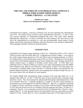
2. Photograph No. 1
Aerial View of Middle Fork Impoundment
Through the development and improvement of fine coal recovery technologies, Clinchfield
determined in 1986 that fine coal fractions, previously unrecoverable in the preparation process,
could be recovered from the Middle Fork Impoundment slurry. The Middle Fork Fine Coal
Recovery Plant was constructed and began dredging operations in 1987. The plant incorporated
flotation and spiral concentration circuits for the recovery process. Dam No. 3 was enlarged to
receive fine reject slurry from the Moss No. 3 and the Middle Fork plants to facilitate dredging
operations between Dam No. 1 and No. 3 and also to provide clarified water to the Middle Fork
Plant. The enlargement of Dam No. 3 also necessitated the extension of the underflow culvert.
3. This was accomplished by joining the 60 inch pipe, now 5,060 feet long, with 3,200 feet of 24
inch cmp with four vertical decant risers spaced evenly along its length. The following events
describe several unique and pressing engineering challenges that had to be met in order to
maintain and maximize the fine coal recovery operation and operate the Middle Fork Slurry
Impoundment in a safe and environmentally sound manner.
Dam No. 1 Dam No. 3
Classification Class C – High Hazard Class A – Low Hazard
Construction Method Centerline/Downstream Centerline/Upstream
Crest Elevation (msl) 2020 2120
Total Height (ft) 400 270
Pool Elevation (msl) 1950 2115
Pool Volume (ac.ft.) 4,275 1,328
Pool Area (ac) 56.7 76.0
Pool Length (ft) 3,100 4,400
Design Storm PMF/Dam No. 3 Breach 100 Year – 48 Hour
Minimum Freeboard (ft) 38.3/18.7 3.1
Ten Day Drawdown 7.7/6.7 Days 7.8
Table No. 1
Current Statistics of Dam Nos. 1 and 3
ENGINEERING CHALLENGES AND SOLUTIONS
Abandonment of 24 inch Upstream Underflow Pipe
During an inspection of the 60 inch underflow pipe in 1993, it was discovered that the transition
zone between the 60 inch and 24 inch culverts was in failure. The failure might have been due to
higher vertical stresses created by additional stages of Dam No. 3. At that time, Stage 5 had
been completed to an elevation of 2060 msl (or 168 feet) above the pipe transition. Due to the
possible effects of piping within Dam No. 3 and possible loss of slurry into the receiving stream,
it was determined that the transition zone would have to be abandoned. It was obvious that
grouting the transition zone was the only solution. However it was not possible to pump a high
strength grout nearly a mile through the 60 inch pipe.
It was then decided that a vertical shaft would be installed in Dam No. 3 to access the transition
zone at a location close enough to supply the required grout. Both an outside drilling contractor
and a grouting contractor were retained for the project. A precise closed loop survey was
conducted within the entire length of the 60 inch pipe, and a favorable drilling location was
spotted on a downstream bench of Dam No. 3, approximately 200 feet outby of the transition
zone. The auger drilling was done with caissons in three segments – a 60 inch diameter and 40
foot segment, a 54 inch diameter and 40 foot segment, and a 48 inch diameter and 35 foot
segment, for a total depth of 155 feet. The auger hit the 60 inch underflow pipe nearly on center,
120 feet of 36 inch cmp was set and grouted for the shaft, the 60 inch underflow pipe/36 inch
shaft connection pressure grouted, and the underflow pipe accessed and prepped for grouting.
Four hundred feet of the 24 inch cmp and 15 feet of the 60 inch underflow pipe were then
4. grouted and the transition zone secured and abandoned. The 36 inch cmp shaft was left in place
which provided natural ventilation, and an escapeway during routine inspections of the 60 inch
pipe, as well as a means for wasting excess clarified water from the Middle Fork Impoundment
operations.
Photographs No. 2 and No. 3
Installation of 60 inch Caisson and 36 inch Shaft Liner
Photograph No. 4
Grout plug in 24 inch Culvert in Transition Zone
5. Installation of Principal Spillway by Directional Drilling
A design requirement for Dam No. 1 concerning the recovery of coal fines from within the
impoundment stated that a 7H:1V slope of existing tailings be maintained on the upstream face
of the dam for seepage control. This material would serve as a seal to prevent water infiltration
of the dam, constructed of coarse refuse, in the event of a design storm PMF and/or the
catastrophic failure of Dam No. 3 and which, if removed, could result in the potential failure of
Dam No. 1 itself. The affect of leaving such a large volume of fines in place would result in the
loss of approximately 540,000 tons of clean coal fines. Thus, in 1994, the question was posed as
to how the recovery operation could gain access to these potentially lost fines, while operating
and maintaining the impoundment in a safe and environmentally sound manner.
Based on seepage and stability modeling, it was determined that a principal spillway pipe, with
invert located at 1950 msl, would adequately maintain the phreatic level within the embankment
so that the additional fines could be recovered. Four potential solutions were studied. The first
approach looked at installing a 36 inch shaft in Dam No. 2 (top elevation 1940 msl), much like
that which was done with great success in Dam No. 3. However, because of uncertainties
surrounding the dam’s construction and the effects of being underwater for several years, we
discounted this plan. Another approach looked at lowering the existing open channel spillway of
Dam No. 1, situated in bedrock, 56 feet. Excavation costs were projected at $600,000, but the
geologic conditions were less than ideal. The third scenario studied involved open cutting the
face of the dam and installing a 24 inch HDPE pipe spillway. This would require excavating
approximately 140,000 cyd of refuse material, installing the pipe, and then extensive compaction
to insure the integrity of the dam during critical storm events. Again, this option presented
serious drawbacks. The fourth plan required the tunneling and installation by directional drilling
a 48 inch steel principal spillway pipe through the face of Dam No 1.
In 1995, a leader in the Directional Drilling industry was contacted and, after a site visit, assured
us that the project could ‘easily’ be done by directional jack and auger boring. In 1997, the
contractor was awarded the Trenchless Technology Industry’s ‘Person of the Year Award’ for
this project. Careful design considerations of the project determined that approximately 50,000
cyd of material would be excavated for a boring pit. For support of the directional drilling
equipment, a one million pound thrust block made of concrete and 10x42 steel H-beams and a
15’x60’x8” thick concrete boring pad, set at a 5.5% upgrade slope, would also be required. A
cathodic protection survey revealed a very low corrosion rate for the refuse and a bare Grade B
Carbon Steel 48 inch diameter, 0.5 inch wall thickness pipe would be used in the jack and bore
process. All drilling operations would take place on the downstream face of the impoundment.
The elevation of water on the upstream face of the dam was near 1946 msl, the invert of the
cutting head was set at 1926.17 msl, and the target was 400 feet upstream at 1950 msl. The
articulated jack and bore auger cutting head was guided by a laser set on the thrust block. The
laser guided the operator, who sat in the cutting head, with the laser’s target above his head.
After several weeks of careful drilling, the cutting head emerged on the upstream face of the dam
with invert at elevation 1950.21 msl. A grouting contractor then proceeded to pressure grout the
interface between the outer wall of the pipe and refuse through 2 inch ports, previously installed
every 20 feet in the pipe walls. A concrete headwall was then installed, the 48 inch pipe
extended through the bore pit, and the site reclaimed with coarse refuse. One half million tons of
clean coal fines were then added to the life of the fines recovery operation.
6. Photographs No. 5 and No. 6
Construction of Thrust Block and Jack and Bore Auger Pad
Photograph No. 7
Jack and Bore Auger Pit
7. Photograph No. 8
Aerial View Of Jack and Bore Auger Pit
Abandoned Impoundment Adds Life to Fines Recovery Operation
When the Middle Fork Recovery Plant was first conceived it was conservatively estimated to
have a production life of four years. Slurry recovery operations began in 1987 and we are now
nearing the end of production. In January, 1998 it was recognized that the fines reserve behind
Dam No. 1 would be depleted sometime between year end 2000 or 2001. Efforts were made to
find additional reserves for the facility.
Adjacent to the Middle Fork Impoundment is the abandoned ‘Thirty Acre Pond’ (actually 43
acres). This slurry impoundment was used by the Moss No. 3 Plant prior to construction of the
Middle Fork Impoundment. The Thirty Acre Pond was abandoned around 1970 due to depleted
storage capacity and observed slope movements and covered with approximately 1.6 million cyd
of coarse refuse. Upon analysis it was determined that the impoundment could be reconstructed
to state reclamation and MSHA impoundment standards. This could be achieved by removing
the 1.6 million cyd of coarse refuse, and in conjunction with 700,000 cyd of coarse refuse feed
from the Moss No. 3 Plant, reconstruct the impoundment and install the proper hydraulic
structures. This would then provide the Middle Fork Plant, based on drilling and sampling
analyses, an additional reserve of 1.6 millions tons of clean coal fines. Once construction of the
Thirty Acre Pond is complete, minimal capital investment will be required for fines recovery and
refuse disposal operations at the Middle Fork/Moss No. 3 Plants for 7 and 15 years respectively.
Initial site preparation and installation of approximately 7,200 feet of underdrains and 4,400 feet
of diversion ditches began in 1998. A massive rock toe buttress consisting of high durability
sandstone and limestone was constructed in 2000. The 1.6 million cyd of coarse refuse material
located on the surface of the impoundment was removed and placed using Cat 777B haulers, a
992 loader, D10N and D475 bulldozers, and a PC400 excavator. Coarse refuse feed from the
Moss No. 3 Plant and terrace construction has since been ongoing, so that the Thirty Acre Pond
8. will be completed and operational by the time the Middle Fork reserves are depleted, projected at
mid-year 2002. When completed the impoundment will be 390 feet high, have a 50 foot crest,
and a 15 foot open channel spillway constructed in bedrock designed to pass a PMF and decant
90% of that PMF in 3.41 days.
Photograph No. 9
Aerial View of the Thirty Acre Pond
Underground Mine Works and Abandonment of the 60 inch Pipe
In 1996, there were two separate events in Virginia that allowed millions of gallons of fine coal
refuse slurry to be released into receiving streams. These incidents were not the result of failure
of the impoundment embankments themselves, but due to unanticipated releases into
underground mine works located beneath the impounding bodies. There are various theories of
how these events occurred, including increased hydrostatic pressures, sudden failure of coal
pillars and/or subjacent support, or perhaps unknown subsidence fractures. The result of these
incidents, however, did raise the profile of fine coal refuse slurry impoundments, how they are
9. designed and constructed, and the degree to which associated nearby underground mine works
and their relation to slurry impoundments are investigated and evaluated.
In February 11, 1997, MSHA issued Program Information Bulletin No. P97-4, a set of guidelines
for coal operators which detailed immediate measures to be taken by MSHA addressing the
breakthrough issue. In a November 26, 1996 internal memo, the Virginia Division of Mined
Land Reclamation (DMLR) implemented a series of measures to be followed in evaluating such
structures:
All current existing permitted slurry impoundments are to be inventoried by December 15,
1996
The slurry impoundments identified in 1 above are to be reviewed to determine if there
are existing underground mine works adjacent to or under the impoundments by January
15, 1997
The slurry impoundments identified in 1 above are to be reviewed to determine if there
are proposed underground mine works adjacent to or under the impoundments by January
31, 1997
If a slurry impoundment is determined to have either existing or proposed underground
mine works, adjacent to or under it, then a Revision Order Notice is to be issued within
three working days which will require the company to address the stability of the slurry
impoundment area, demonstrating an adequate barrier to prevent a breach of the slurry
into the mine works (unless this demonstrations has already been performed to the
satisfaction of the Division)
All new proposed slurry impoundments or modifications of existing slurry impoundments
shall be required to provide this demonstration. Verification of existing or proposed
underground mine works shall be part of the permit review for these revisions or permit
applications
The Division shall use the ‘Mine Blow Out’ criteria to review the stability of slurry
impoundment area and the adequacy of barriers from underground mine works. In
reviewing the slurry impoundment stability and barrier adequacy, the adequacy of internal
mine barriers shall be considered as well.
As is the case with many slurry impoundments, the Middle Fork Impoundment does have an
abandoned underground mine beneath it located in the Jawbone seam. The relationship between
the Middle Fork Impoundment and the Jawbone mine was investigated in 1978, and a report was
submitted to MSHA with specific recommendations and findings. After 1996, a comprehensive
study was initiated to evaluate the potential of a sudden loss of slurry fines into these mine works
as per DMLR’s criteria. A report – ‘Results of Research to Develop Guidelines for Mining Near
Surface and Underground Bodies of Water’ published by the Bureau of Mines, and the text,
Surface Subsidence Engineering, by Syd S. Peng were used to evaluate the breach potential and
subsidence effects between the impoundment and the Jawbone mine.
Because there was more extensive mining beneath Dam No. 3 than Dam No. 1, the analysis was
concentrated on the more critical Dam No. 3. The Jawbone mine works lie approximately 240
feet beneath the natural valley bottom of Dam No. 3. Interburden between the Jawbone roof and
Dam No. 3 consists of two massive strata of sandstone with a massive shale stratum between the
10. two. No secondary mining has occurred in this area. Some secondary mining has occurred in
the upper reaches of the Dam No. 3 pool area, which has approximately 300 feet of similar
interburden. Based on the site specific conditions and published supporting documentation, it
was determined that an adequate amount of cover exists to resist a breach into the mine works.
As the fines recovery operation continued to remove coal fines in approximate 25 foot lifts, the
dredge’s cutting head was also moving closer to the 60 inch underflow culvert. This raised
another possibility of a sudden loss of slurry fines into nearby streams. In November, 2000, a
plan was submitted to MSHA to abandon the 60 inch culvert to insure that no potential loss of
slurry would exist. At that time the water elevation behind Dam No. 1 was at or near 1875 msl
and a minimum of 90 feet above the 60 inch culvert. The maximum depth that the dredge can
penetrate beneath the water elevation is approximately 30 feet, which left a safety zone of 60
feet. In August, 2001, approval from the regulatory agencies was received and a grouting
contractor was retained.
The approved plan followed by the contractor required cleaning and grouting approximately
1,480 feet of the downstream section of the culvert which lies directly beneath the structural
portion of Dam No. 1. All sediments and debris were removed within this grout zone. A 1,520
foot length of 10 inch HDPE pipe was installed within the grout zone to allow the Middle Fork
Plant facility to continue to waste excess water through the 36 inch shaft located on Dam No. 3.
Grouting operations used various lengths of 3 inch HDPE pipe and 2 and 3 inch Schedule 80
PVC pipe for grout and vent lines, as dictated by the location of the bulkheads, and ½ inch PVC
lines for chemical grout applications around the 100 foot plug zones. Several small seeps were
grouted with a hydroactive grout to minimize infiltration during the grouting operation. A 100
foot long high-strength grout plug was installed at the upper end of the 1,480 foot grout zone.
Utilizing temporary bulkheads, sections approximately 200 feet long were then grouted, using a
low-strength, light-weight grout to fill a filler zone of 1,280 feet. A final 100 foot long high-
strength grout plug then completed the operation. Once grout was returned through the vent
lines, the vent line valves were closed and maximum pressure applied to insure the zone was
completely filled. A gate valve was installed at the outlet end of the 10 inch pipe to allow shut
off of flow should the need arise. This project was successfully completed in February, 2002.
Photographs Nos. 10 and 11
Surface Grouting Facilities and Temporary Grout Bulkhead
11. Future Use
Refuse disposal operations at the Moss No. 3 Preparation Plant complex will require minimal
capital investment for the next fifteen years. Dam No. 3 will continue to receive fine refuse for
approximately 2.5 years. Once clarified water for the Middle Fork Plant is impacted from
encroaching refuse fines, the 4,200 gpm turbine pump, located in the upper reaches of Dam No.
3, will be relocated within the confines of Dam No. 1. Dam No. 3 will continue to receive fine
refuse and then reclaimed utilizing either coarse refuse or excess spoil generated from a potential
surface mine within the confines of the Middle Fork watershed. The Middle Fork Plant will
continue to recover and process coal fines upon completion of construction of Phase I of The
Thirty Acre Pond. Dam No. 1 can then receive both coarse and fine refuse generated from the
Moss No. 3 and the Middle Fork Plants and will eventually be reclaimed. An abandoned slurry
impoundment located five miles from the Middle Fork Plant has just received tentative approval
from MSHA for fine coal recovery which can be mined dry and trucked to the Thirty Acre Pond
for processing. The Thirty Acre Pond currently has three additional stages available for coarse
refuse disposal on its downstream face. In addition, once the fine coal reserve has been
exhausted from the Thirty Acre Pond, the impoundment will then be available for fine and/or
coarse refuse disposal. This is the life and times of Clinchfield Coal Company’s Middle Fork
Slurry Impoundment.
SUMMARY
The American Coal Industry has consistently evolved in order to maintain its position as the
premier supplier for this nation’s source of low cost energy and supplier of high quality coking
coals. Through innovation and vision, our industry continues to strive to improve efficiencies, as
well as improve both the miner’s and the public’s health and safety, all the while protecting and
restoring the environment. The Moss No. 3 and Middle Fork Plant facilities have been operated
in a manner which has protected the health and safety of the public, minimized impacts to the
environment, and recovered a previously abandoned energy source which equates to millions of
barrels of imported oil.
ACKNOWLEDGEMENTS
We would like to thank the staff of the Mine Safety and Health Administration’s Pittsburg Safety
and Health Technology Center, for their assistance in reviewing numerous engineering
proposals. In addition, Mr. Leo Barbera of Horizontal Holes International, Inc., Mr. Stephen D.
Hawkins of Hayward Baker, Inc., and McKinney Drilling Company for their drilling and
grouting assistance. Without the cooperation and dedicated service from Mr. Fred Stanley,
Manager of Preparation, Pittston Coal Management Company, Mr. Paul King, Jr., Moss No. 3
Plant Superintendent, and Mr. Tom Penland, Moss No. 3 Plant Lead Foreman, Clinchfield Coal
Company, as well as the staff of Geo/Environmental Associates, Inc., this presentation would not
have been possible.