
Recommended
More Related Content
What's hot
Similar to US8053584
Similar to US8053584 (20)
US8053584
- 1. US008053584B2 (12) Ulllted States Patent (10) Patent N0.: US 8,053,584 B2 Meerdink et al. (45) Date of Patent: Nov. 8, 2011 (54) PURIFICATION PROCESS FOR LACTIDE (51) Int. Cl. C07D 313/00 (2006.01) (75) Inventors: Johannes Meerdink, Groningen (NL); B01D 3/00 (200601) Nils Dan Anders Sadergard, Turku (Fl) C08G 63/82 (200601) (52) US. Cl. .......... 549/274; 203/99; 528/354; 528/357; (73) Assignee: Tate & Lyle Public Limited Company, 528/361; 528/480; 528/481; 528/484; 528/485 London (GB) (58) Field of Classi?cation Search ................ .. 549/274; 528/354, 480, 481, 484, 485, 357, 361; 203/99 ( * ) Notice: Subject to any disclaimer, the term ofthis See apphcanon ?le for Complete Search hlstory patent is extended or adjusted under 35 (56) References Cited U.S.C. 154(b) by 807 days. US. PATENT DOCUMENTS (21) APP1~ NOJ 10/582,280 5,023,350 A 6/1991 Bhatia ....... .. 549/274 5,117,008 A 5/1992 Bhatia et a1. ..... .. 549/274 (22) PCT Filed; Dec_ 10 2003 5,236,560 A 8/1993 Drysdale et a1. 203/99 , 5,521,278 A 5/1996 O’Brien et a1. ............. .. 528/354 (86) PCT N0.: PCT/NL03/00875 Pr’rfmry Exam?” * Andrew D K052,“ ASSlSZLlI’lZ Exammer * Raymond Covlngton § 371 (6X1), (74) Attorney, Agent, or Firm * Williams, Morgan & (2), (4) Date: Feb. 20, 2008 Amerson, RC (87) PCT Pub. No.: WO2005/056509 (57) ABSTRACT _ _ The present case relates to a process for the pun?catlon of PCT Pub- Date: Jun- 23’ 2005 lactide from a crude lactide Vapor product stream Which pro cess comprises a recti?cation/condensation step leading to a (65) Prior Publication Data lactide-enriched condensate. US 2008/0234500 A1 Sep. 25, 2008 21 Claims, 1 Drawing Sheet 19 V 29 1D 11 17 l 21 2 g _ ll 8 12 7 “+4 16 4 A 15 5 6 --r- +3‘13LI». 1 24 ‘ 25 "‘“__’ 1 —--~—> 2 1B w 26 v 27 ‘"59"’14 -——--———--> 23
- 2. Nov. 8, 2011 US 8,053,584 B2US. Patent
- 3. US 8,053,584 B2 1 PURIFICATION PROCESS FOR LACTIDE This invention relates to an improved process for the puri ?cation oflactide from a crude lactide vapour product stream comprising at least said lactide, lactic acid, Water and linear lactic acid oligomers. Lactides are dimeric cyclic esters of lactic acid and are intermediates in the preparation process of high molecular Weight (HMW) polylactic acids (PLA), Which are truly bio degradable polymers that can be utilised as substitutes for non-biodegradable polymers. The use of lactic acid and lac tides for the manufacture of a biodegradable polymer is Well knoWn in eg the biomedical industry, Where the polymer is used for making biodegradable sutures, clamps, bone plates and biologically active controlled release devices. Lactide is most conveniently prepared by a tWo-step poly merisation/depolymerisation process. First, lactic acid from a feed source is polymerised to a relatively loW molecular Weight (oligomeric) polylactic acid (LMW-PLA). Second, the LMW-PLA is heated, generally in the presence of a cata lyst, to depolymerise the LMW-PLA to lactide Which is recovered as a component of a vapour product stream. Meth ods for performing the said polymerisation and depolymeri sation are knoWn in the art, see eg Gruter et al., U.S. Pat. No. 1,095,205 (1914); LoWe, U.S. Pat. No. 2,668,162 (1954); Bhatia, U.S. Pat. No. 4,835,293 (1989); DeVries, U.S. Pat. No. 4,797,468 (1989); and Muller, U.S. Pat. No. 5,053,522 (1991). To obtain the high molecular Weight polylactic acid (HMW-PLA) required for use as a biodegradable polymer it is essential that the lactides are obtained essentially free of other impurities, such as Water, lactic acid, linear lactic acid oligomers and volatile derivatives of lactic acid, as in the presence of such impurities polylactic acid of insuf?ciently high molecular Weight is obtained. Thevapourproduct streamthat is producedby depolymeri sation not only comprises lactide but also the above-men tioned impurities. In particular Water and lactic acid are capable of participating in ring-opening reactions With the lactide, Which results in a loWer lactide yield and an increased acidity ofthe cyclic ester product. Typically, puri?cation of lactide may be achieved by sol vent extraction or by recrystallisation from solvent. HoWever, both methods are disadvantageous as they utilise solvents, Which necessitates the need for facilities to store a solvent, to purify the product therefrom and to prevent the solvent from escaping into the environment. Hence, such steps add signi? cantly to the process investment and operating costs. More over, recrystallisation is knoWn to give relatively poor yields due to signi?cant losses oflactide during the recrystallisation step. For the large-scale commercial production of biode gradable polylactic acid for an abundance ofapplications it is important to maximise yields and minimise costs to obtain a cost-competitive product. Alternatively, distillation can be employed to purify lactide from a crude lactide vapour product stream (see eg EP 0 893 462 and EP 0 630 371, Which are hereby incorporated herein by reference). The use of distillation for the puri?cation of lactide alloWs for the continuous manufacture of cost-com petitive HMW-PLA. As an example, EP 0 630 371 discloses the use offractional distillation for puri?cation of lactides. Thereto, a crude lac tide vapour stream that is produced by the depolymerisation of LMW-PLA in a reactor is completely or partially con densed and subsequently fed to a multi-stage distillation col umn. Three fractions are established in the column and removed therefrom: an overhead vapour fraction comprising 20 25 30 35 40 45 50 55 60 65 2 lactic acid and Water, a side vapour fraction comprising lac tide and a bottom liquid fraction comprising lactide and linear lactic acid oligomers. The side vapour fraction comprising lactide may be condensed to yield a liquid lactide fraction. A purge stream ofthe bottom liquid fraction comprising lactide and linear lactic acid oligomers may be fed to the reactor such that the linear lactic acid oligomers may reparticipate in the depolymerisation reaction to optimise overall lactide yield. HoWever, lactide With an acid content loW enough to produce HMW-PLA Was obtained only With very loW yields. EP 0 893 462 describes the use of distillation for puri?ca tion oflactides. The crude lactide vapour stream may be fed to a conventional distillation column as such or may be com pletely or partially condensed prior to feeding to the column. Moreover, a distillation column is disclosed Which is mounted directly on top of a reactor to create a single enclosed area Within Which both the reaction to generate the crude lactide vapour stream, and distillation thereof take place. It is disclosed that in the top-mounted distillation col umn equilibrium is established betWeen loW-boiling over head components such as Water and lactic acid, the interme diate-boiling component lactide and the high-boiling components, i.e. linear lactic acid oligomers; thus, a three component separation is attempted. The high-boiling compo nents, i.e. the linear lactic acid oligomers, that liquefy Within the column travel doWn the distillation column directly into the reactor Where they can be further reacted to form addi tional lactide. Thus, no purge stream is required betWeen the distillation column and the reactor to obtain maximal LMW PLA conversion and thus lactide yield. The loW-boiling over head stream composed essentially of Water (or solvent) and lactic acid is removed, subsequently condensed and a portion is re?uxed back into the distillation column. The desired product, i.e. the lactide, herein also referred to as the “lactide fraction” or “lactide containing fraction”, is recovered via a side outlet. HoWever, such top-mounted three-component separation system is very dif?cult to operate, particularly taking into account the fact that the system is located on top of a reactor, and it is dif?cult to envision that high yields of lactide With an acid content suf?ciently loW to produce HMW-PLA can thus be obtained. In order to obviate one or more ofthe above draWbacks, the present invention provides an improved process for the puri ?cation oflactide Withhighyield andhighpurity, Whereinthe lactide is pre-puri?ed in a recti?cation column separating the non-volatile components, i.e. linear lactic acid oligomers, and preferably a majorpart ofthe volatile components such as eg Water and lactic acid, from the desired end-product lactide to increase the yield and purity of the lactide. Thus, the present invention relates to a process for the puri?cation of lactide from a crude lactide vapour product stream comprising at least said lactide, lactic acid, Water and linear lactic acid oligomers, said crude lactide vapour product streambeing producedby depolymerisation ofloW molecular Weight polylactic acid in a reactor, Which process comprises the steps of: (a) feeding said vapour product stream to a recti?cation column having a feed inlet at the loWer end ofthe column and an overhead vapour outlet at the upper end of the column, through the said feed inlet, said column being mounted onto the reactor such that components from the vapour product stream liquefying Within the column are alloWed to How back into the reactor; (b) establishing at the upper end of the column a ?rst overheadvapour fractionconsisting essentially ofWater, lactic acid and lactide, and at the loWer end ofthe column
- 4. US 8,053,584 B2 3 a high-boiling fraction consisting essentially of lactide and higher-boiling linear lactic acid oligomers; (c) condensing from said ?rst overhead vapour fraction by means of a condenser at least the lactide to obtain a ?rst liquid lactide containing condensate fraction; (d) removing the ?rst liquid lactide containing condensate fraction. As knoWn in the art, LMW-PLA and one or more catalysts can be fed to the reactor, Where the crude lactide vapour product stream is produced by heating of the LMW-PLA in the presence of a catalyst. Suitable catalysts that may be present in the reactor are Well knoWn in the art and may comprise metals or inorganic/organic metal compounds such as Sn, Ti, Zn or Fe compounds. TWo optical isomers are knoWn to exist for lactic acid, L-lactic acid and D-lactic acid. Either of the tWo lactic acid isomers or mixtures thereofmay be used for the production of LMW-PLA and subsequent production of lactide to yield L-lactide, D-lactide and meso-lactide (DL-lactide) in any combination. A typical depolymerisation reaction is conducted at a pres sure of 10-100 mbar, preferably 20-50 mbar, at temperatures in the range of 160-2700 C., preferably of 180-2500 C., more preferably of200-2500 C. However, the depolymerisation can be conducted using any pressure and temperature. A skilled practitioner Will readily be able to adjust these parameters. Under the above conditions, the lactide produced by the depolymerisation of the LMW-PLA is removed by evapora tion resulting in a crude lactide vapour product stream. In order to enhance the said removal, it is advantageous to apply a stream of an inert gas, such as eg nitrogen or argon gas in the reactor. The said crude lactide vapour product stream comprises at least lactide, lactic acid, Water and linear lactic acid oligomers, such as linear lactic acid dimers, trimers, tetramers and higher oligomers, but may also comprise addi tional components, e.g. volatile lactic acid derivatives such as pyruvic acid. The composition of the crude lactide vapour product stream may depend on several parameters, such as for example the reaction temperature and pressure, the molecular Weight ofthe introduced LMW-PLA and the type and amount ofcatalyst and/or initiator used. Typically, the lactide content in the crude lactide vapour product stream may be inthe range of 65-99 Wt. %, the lactic acid content may be in the range of 0-15 Wt. % and the content oflinear lactic acid oligomers may be in the range of 0-20 Wt. % (see eg example 2 and 3). The crude lactide vapour product stream may additionally com prise by-products generated during the depolymerisation of LMW-PLA, such as e.g. pyruvic acid and acrylic acid, having an atmospheric boiling point of 1650 C. and 1400 C., respec tively. According to the invention, the crude lactide vapour prod uct stream is directly fed to a recti?cation column. Entrance of the recti?cation column is therefore preferably not pre ceded by a condensation step. The term “recti?cation” is Well knoWn in the art and re?ects the process of puri?cation by means of fractionation based on volatility differences betWeen components. The relative order of decreasing vola tility ofthe principal components ofthe said stream is Water, lactic acid, lactide and linear lactic acid dimers and higher oligomers With boiling points at atmospheric pressure of about 100, 215, 260 and 3500 C., respectively, Which boiling points are even higher for linear lactic acid trimers, tetramers, etc. The more volatile components in the said stream, such as Water, lactic acid, lactide and volatile lactic acid derived spe cies, such as for example acrylic acid and pyruvic acid, are evaporated more easily than the less volatile components, such as linear lactic acid dimers and higher oligomers, and 20 25 30 35 40 45 50 55 60 65 4 thus travel higher in the column. As a consequence, a concen tration gradient is established With the more volatile compo nents being enriched at the upper end of the column and the less volatile components being enriched at the loWer end of the column. Due to this concentration gradient a temperature gradient exists over the column. Thus, in the loWer end ofthe column the temperature is highest and the concentration of the most volatile components, i.e. Water, lactic acid and lac tide, is loWest, and in the upper end of the column the tem perature is loWest and the concentration of the most volatile components is highest. Most e?icient separation is achievedWhen at least a portion ofthe ?rst liquid lactide containing condensate fraction ofthe more volatile components is re?uxed, such that vapour and liquid fractions display a counter-?ow Within the column. Thus, an ef?cient separation is accomplished betWeen com ponents With a higher and components With a loWer volatility. The person skilled in the art of recti?cation is aWare of suit able conditions or is capable of establishing the said condi tions in a straightforWard manner in order to optimise the above separation. As a concentration gradient ofthe compounds is present in the recti?cation column, outlets can be positioned in the column such, that fractions enriched in a desired product, eg lactide, can be removed from the column at the position ofthe said outlet. According to the present invention, the concen tration gradient is established such, that the overhead vapour fraction at the upper end of the column is enriched in Water, lactic acid and lactide, Whereas the bottom vapour fraction at the loWer end of the column is enriched in lactide and linear lactic acid oligomers. The lactide fraction is WithdraWn at the upper end ofthe column. According to the invention, said recti?cation column is mounted With its loWer end onto the reactor such that a single enclosed area is provided Wherein both the lactide production and puri?cation take place. As a consequence, components liquefying in the recti?cation column are alloWed to directly ?oW back into the reactor as to enable re-participation in the depolymerisation reaction. Thus, no purge stream as eg described in EP 0 630 371 is required to improve lactide yield. The recti?cation column can be any type ofknoWn recti?ca tion column alloWing contact betWeen the vapour and liquid fractions, such as eg a tray column or a packed column. Preferably, the recti?cation column is a packed column as packed columns are more conveniently used at reduced pres sures. Preferably, the recti?cation column is packed With structured packing material in order to enhance contact betWeen the vapour and liquid and to minimise the liquid hold-up. Minimising the liquid hold-up results in a loWer pressure drop over the column. The skilled person is capable of applying the proper packing material for the envisaged aim. It is preferred that the recti?cation is conducted under reduced pressures. The crude lactide vapour product stream produced in the reactor thus enters at the loWer end ofthe recti?cation column at the feed inlet. The feed inlet is de?ned to be the column opening Where the column is joined to the reactor. Herein, “loWer end” de?nes a loWer region in the column; loWer end does therefore not necessarily mean the bottom ofthe column but may also be a location in the vicinity thereof. At the upper end of the column, i.e. the end ofthe column that is not connected to the reactor, a ?rst overhead vapour fraction is established consisting essentially of Water, lactic acid and lactide, and at the loWer end ofthe column a vapour fraction is established consisting essentially of lactide and higher-boiling linear lactic acid oligomers. One skilled in the art Will be capable ofdetermining and controlling appropriate
- 5. US 8,053,584 B2 5 pressures, temperatures and ?oWs in the column to establish such fractions. Herein, “upper end” de?nes an upper region in the column; upper end does therefore not necessarily mean the top ofthe column but may also be a location in the vicinity thereof. However, preferably, the upper end ofthe column is at the top of the column. From the ?rst overhead vapour fraction in the upper end of the column at least the lactide is condensed by means of a condenser to obtain a ?rst liquid lactide containing conden sate fraction, and said ?rst liquid lactide containing conden sate fraction is removed from the column. Said ?rst liquid lactide containing condensate, herein also referred to as rec ti?ed lactide, comprises lactide and may comprise Water and lactic acid, but is preferably substantially void oflinear lactic acid oligomers. Thus, the ?rst liquid lactide containing con densate is essentially free of linear lactic acid oligomers and is therefore substantially puri?ed in comparison to the crude lactide vapour product stream. In a preferred embodiment step c) in the above process comprises partially condensing said ?rst overhead vapour fraction, such that at least the Water is left in the vapour phase and removed from the condenser, and at least the lactide is condensed to obtain a ?rst liquid lactide containing conden sate fraction. Thus, a more puri?ed ?rst liquid lactide con taining condensate fraction is obtained mainly comprising lactide and possibly also lactic acid, but essentially void of both linear lactic acid oligomers and Water. Preferably at least 80 Wt. % of the Water is removed in the vapour phase, more preferably at least 90 Wt. %, even more preferably at least 95 Wt. %, most preferably at least 98 Wt. %. Therefore, the obtained ?rst liquid lactide containing condensate fraction is substantially puri?ed in comparison With the crude lactide vapour product stream, as the said condensate fraction com prises substantially less, or no Water and less, or no linear lactic acid oligomers. In a more preferred embodiment said step c) comprises partially condensing said ?rst overhead vapour fraction, such that at least the Water and a major amount ofthe lactic acid are left in the vapour phase and removed from the condenser, and at least the lactide is condensed to obtain a ?rst liquid lactide containing condensate fraction, Which results in an evenmore puri?ed ?rst liquid lactide containing condensate fraction comprising lactide and a minor amount of lactic acid, said fractionbeing essentially void oflinear lactic acid oligomers, Water and a major amount oflactic acid. Preferably at least 80 Wt. % of the Water is removed in the vapour phase, more preferably at least 90 Wt. %, even more preferably at least 95 Wt. %, most preferably at least 98 Wt. %. Preferably at least 50 Wt. % ofthe lactic acid is removed in the vapour phase, more preferably at least 60 Wt. %, yet more preferably at least 70 Wt. %, again more preferably at least 80 Wt. %, most preferably at least 90 Wt. %. Condenser temperatures required for complete or partial condensation of lactide may vary. One skilled in the art Will readily be able to determine suitable condenser temperatures. The (partial) condenser may be mounted on top of the recti ?cation column or may be located doWnstream ofthe recti? cation column. In order to ef?ciently remove the linear lactic acid oligo mers from the crude lactide vapour product stream, a portion of the ?rst liquid lactide containing condensate fraction is preferably re?uxed into the column. The “re?ux ratio” is a measure ofhoW much ofa liquid condensate is returned back to the column as re?ux and is de?ned as the ratio ofthe liquid condensate ?oW re?uxed into the column to the liquid con densate ?oW removed from the column. The re?ux ratio is preferably betWeen 0.01 and 5, more preferably betWeen 20 25 30 35 40 45 50 55 60 65 6 0.025 and 2, most preferably betWeen 0.05 and l. A re?ux ratio of 5 means eg that ofthe condensed matter 5 volumes are returnedto the column whereas 1 volume is removed from the column. Advantageously, the ?rst liquid lactide containing conden sate fraction comprises at least 90 Wt. % lactide and 0-10 Wt. % lactic acid, more preferably at least 96 Wt. % lactide and 0-4 Wt. % lactic acid. Depending on the desired purity of the lactide, the ?rst liquid lactide containing condensate fraction of step d) may be subjected to one or more distillation steps. Said distillation steps can be performed as is knoWn eg from EP 0 623 153 and EP 0 893 462 or EP 0 630 371, but any type ofdistillation knoWn in the art may be employed to further purify the ?rst liquid lactide containing condensate fraction. In a preferred embodiment, said one or more distillation steps comprise the steps of: (i) feeding the ?rst liquid lactide containing condensate fraction into a distillation column, the column having a bot tom end and a top end and a feed inlet betWeen said bottom end and top end, the column further comprising a second overhead vapour outlet at the top end ofthe column, a liquid outlet at the bottom end and a vapour side outlet located betWeen the feed inlet and the liquid outlet; (ii) establishing a second overhead vapour fraction comprising lactic acid and optionally Water in the top end of the column, a bottom vapour fraction comprising lactide in the bottom end of the column, and a bottom liquid fraction beloW the bottom vapour fraction comprising lactide and linear lactic acid oligomers; (iii) removing second overheadvapourfractionthroughthe overhead vapour outlet; (iv) removing bottom vapour fraction comprising lactide through the vapour side outlet; (v) removing bottom liquid fraction through the liquid outlet. For further puri?cation the ?rst liquid lactide containing condensate fraction is fed to a distillation column, herein also referred to as “second column”. This second column com prises a feed inlet located betWeen the top end and the bottom end ofthe column, Whereto the ?rst liquid lactide containing condensate fraction is fed. Preferably, the feed inlet is located at a distance of both the top end and the bottom and of the column, preferably near a midpoint of the column. The distillation column may be any type ofcolumn knoWn in the art alloWing contact betWeen the vapour and liquid fractions, such as eg a tray column or a packed column. Preferably, the distillation column is a packed column as such column is more conveniently used at reduced pressures. Pref erably, the distillation column is packedWith structuredpack ing material as to enhance contact betWeen the vapour and liquid and to minimise liquidhold-up, Which results in a loWer pressure drop over the column and in minimisation of reac tion betWeen the different species present. The skilled person is capable of applying the proper packing material for the envisaged aim. In the process ofdistillation, as knoWn in the art, a concen tration gradient is established With the loW-boiling compo nents being enriched in the top end of the column, and the high-boiling components being enriched at the bottom end of the column. Thus, the second overhead vapour fraction is established in the top end ofthe column Which is enriched in loW-boiling components, i.e. lactic acid and optionally Water. The liquid bottom fraction essentially comprises lactide and high-boiling linear lactic acid oligomers, the latter being formed due to side-reactions occurring under the operating
- 6. US 8,053,584 B2 7 conditions ofthe second column, Whereas the bottom vapour fraction just above the bottom liquid fraction Will consist essentially solely oflactide. Preferably, a reboiler is located at the bottom end ofthe column, generating the energy required for the puri?cation. The second overhead vapour fraction comprising lactic acid and optionally Water is removed through the overhead vapour outlet and may subsequently be fed to a condenser to form a liquid lactic acid containing condensate fraction. Par ticularly When the second overhead vapour fraction still com prises Water, the condenser can be a partial condenser to remove Water to also generate a puri?ed liquid lactic acid condensate fraction. Preferably, a portion of the generated liquid lactic acid containing condensate fraction is re?uxed back into the second column in order to obtain e?icient sepa ration betWeen lactic acid and lactide. The re?ux ratio is preferably in the range of0. 1 -20, more preferably inthe range of 05-15, most preferably in the range of 1-10. The bottom vapour fraction comprising lactide is removed through a vapour side outlet located betWeen the bottom end and midpoint of the second column. Preferably, the vapour side outlet is located slightly above the boiling liquid bottom fraction, such that essentially solely lactide is removed through the said vapour side outlet. Preferably, a portion of the bottom liquid fraction is removed from the second column to prevent accumulation of linear lactic acid oligomers in the liquid fraction. The feed rate of the ?rst liquid lactide containing conden sate fractionto the column and the removal rates ofthe second overhead vapour fraction, the bottom vapour fraction and the bottom liquid fraction are preferably co-ordinated such that a substantially steady-state condition can be maintained in the column as to alloW for a continuous process to occur. One skilled in the art Will readily be able to establish suitable feed and removal rates. In the distillation step, best results are achieved at loW temperatures and pressures. LoWer temperatures minimise the possible occurrence of side-reactions betWeen lactic acid and lactide that can lead to product loss and contamination of the bottom vapour fraction comprising lactide. Preferably, the distillation step is carried out under reduced pressures, more preferably at pressures of 10-100 mbar, most preferably of 20-50 mbar, preferably at a temperature ofno more than 180° C., more preferably of no more than 170° C., even more preferably ofno more than 160° C., preferably ofabout 150° C. Moreover, it is preferred that the processes ofdepolymeri sation of LMW-PLA, recti?cation and distillation are con ducted in a continuous manner. In a preferred embodiment said distillation step further comprises the step of (vi) condensing the bottom vapour fraction comprising lactide obtained in step (iv) to obtain a second liquid lactide containing condensate fraction. Con densation is preferred as lactide in liquid condensed form is more easily fed to any folloWing system, eg an additional puri?cation system or a polymerisation, system. The bottom vapour fraction and/orthe second liquid lactide containing condensate fraction that are obtained as described above preferably comprise at least 99 Wt. %, preferably at least 99.5 Wt. %, lactide. The amount ofhydroxyl containing compounds in the bottom vapour fraction and/or second liq uid lactide containing condensate fraction are preferably less than 50 meq/kg, more preferably less than 20 meq/kg and most preferably less than 10 meq/kg. Thus, a polymer grade lactide is obtained Which is e.g. suitable for the production of HMW-PLA. 20 25 30 35 40 45 50 55 60 65 8 In another embodiment, the bottom liquid fraction of the distillation step is recycled to the reactor to optimise overall lactide yield from a feed source. In a further aspect, the invention relates to a process as disclosed above, said process further comprising the step of removing carboxylic acid and/or hydroxyl containing com pounds in any ofthe lactide comprising fractions obtained in step (d), (iv), (v) or (vi) to further purify the said lactide comprising fractions. Said removal ofresidual acids can eg be accomplished by Well-knoWn processes in the state of the art, such as the addition oforganic bases such as pyridine and trialkylamines or phosphines to the lactide comprising fraction to form salts Withthe acids, scavenging ofacids Withbasic metal salts orby using activated charcoal or silica or alumina poWders Whereto the acids adsorb. HoWever, any chemical process for the removal of carboxylic acid and/or hydroxyl containing com pounds from any of the lactide comprising fractions can be used. The lactide comprising fraction can be obtained in step (d), (iv), (v) or (vi) and comprises at least lactide and optionally lactic acid, Water and linear lactic acid oligomers. HoWever, other carboxylic acid and/orhydroxyl containing compounds may also be present. The lactide comprising fraction may be vaporous such as the lactide comprising fraction obtained in step (iv) or may be liquid such as the lactide comprising fraction obtained in either ofthe steps (d), (v) or (vi). Preferably, said removing carboxylic acid and/or hydroxyl containing compounds in any ofthe lactide comprising frac tions obtained in step (d), (iv), (v) or (vi) comprises the steps of: I. contacting any of the lactide comprising fractions obtained in step (d), (iv), (v) or (vi) With a solid scaven ger material comprising at least one functional moiety capable of forming a covalent bond With one or more carboxylic acid and/or hydroxyl containing compounds optionally present in said lactide comprising fraction, thereby alloWing the at least one functional moiety ofthe scavenger material to selectively react With the one or more carboxylic acid and/or hydroxyl containing com pounds optionally present in said lactide comprising fraction to form a bond thereWith; II. separating the scavenger material With bound carboxy lic acid and/or hydroxyl containing compounds from the lactide comprising fraction to obtain a substantially puri?ed lactide comprising fraction. The latter scavengingprocess forremoving carboxylic acid and/or hydroxyl containing compounds such as Water, lactic acid and linear lactic acid oligomers from a lactide compris ing fraction comprising at least lactide is advantageous, as it does not have the drawbacks conventional processes have. Theremoval ofacids by addition oforganic bases is generally not suitable at elevated temperatures, many nitrogen-contain ing bases shoW a tendency to oxidise and colour the acid containing mixture, and metal ion may act as catalysts, espe cially in mixtures containing polymerisable molecules, such as lactic acid containing mixtures. A major draWback of the charcoal and silica or alumina poWders is the loW capacity at loW acid concentrations and at high temperatures. The above irreversible scavenging process is suitable not only forremoval oflactic acid and linear lactic acid oligomers from a lactide comprising fraction comprising at least lactic acid and lactide, but can be used forremoval ofany carboxylic acid and/or hydroxyl containing compound(s) from any mix ture of compounds to obtain a substantially puri?ed product.
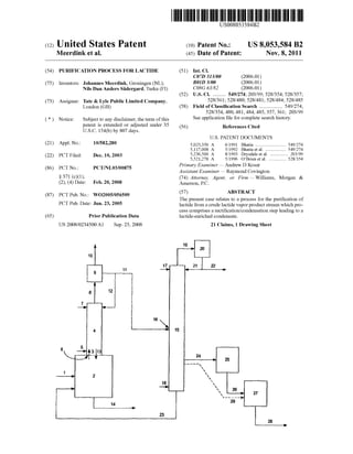
- 7. US 8,053,584 B2 Moreover, the said process can be used for removal of lactic acid and/or linear lactic acid oligomers from any lactide con taining preparation. The solid scavenger material can eg be in the form of a poWder, beads, ?bers, strand, Woven or non-Woven materials. Such materials can easily be separated from a liquid With any viscosity. The scavenging process can be performed in any type of system that alloWs contacting the lactide comprising fraction, either in vapour or liquid form, With the solid scavenger material. Methods for contacting and separating the lactide comprising fraction and the solid scavenger material Will be readily apparent to one skilled in the art. Said contacting could for example be accomplished by passing a vaporous lactide comprising fraction, such as the lactide comprising fraction obtained in step (iv), along a surface comprising the solid scavenger material, or simply by mixing a liquid lactide comprising fraction, such as the lactide comprising fraction obtained in step (d), (v) or (vi), With beads comprising the solid scavenger material. Separation ofthe lactide comprising fraction and the scavenger material can be accomplished by any conventional means such as eg ?ltration. By choosing a speci?c functional moiety the acid scaveng ing process canbe ?ne-tuned. E.g. isocyanates react relatively fast With hydroxyl groups, anhydrides are knoWn to react relatively fast With alcohol groups, epoxidised groups are particularly suitable for removal of compounds With a car boxylic acid group, etc. Preferably, the at least one functional moiety of the scavenger material is selected from the group, consisting ofepoxy, amine, amide, cyano and anhydride moi eties. Non-limiting examples of such reactive moieties are resins based on ole?nic copolymers containing maleic anhy dride acryl amide or glycidylmethacrylate comonomers. The scavenger process can be carried out in a batch or continuous Way. Preferably, the acid scavenging is conducted in a continuous manner to provide an ef?cient and cost effective process. Preferably, the acid scavenging is con ducted at elevated temperatures, more preferably at tempera tures in the range of l 00- 1 80° C., most preferably in the range of l00-l50° C. The invention Will noW be illustrated With reference to ?gures and examples. Referring noW to FIG. 1, LMW-PLA is fed through line 1 to a reactor 2. In the reactor 2 lactide is produced by depoly merisation of the LMW-PLA at a temperature and pressure suf?cient to vaporise the lactide as it is generated, resulting in a crude lactide vapour product stream (arroW 3). Reactor 2 may contain the required catalyst; alternatively, the catalyst can be fed to the reactor 2 by a separate line (not shoWn) or may be co-fed With the LMW-PLA via line 1. The crude lactide vapour product stream 3 enters a recti? cation column 4 that is mounted onto the reactor 2 such that the reactor 2 and the column 4 form a single enclosed area. The crude lactide vapour product stream 3 enters the recti? cation column 4 at the loWer end 5 ofthe column through feed inlet 6. In order to enhance removal of the produced lactide from the reactor 2 to the column 4, a stream ofnitrogen or any other inert gas may be inserted into the reactor 2 (not shoWn). The more volatile components of the crude lactide vapour product stream 3 are being enriched at the upper end 7 ofthe column 4, Whereas less volatile components are enriched at the loWer end 5 of the column 4. As a consequence, in the upper end 7 ofthe column 4 a ?rst overhead vapour fraction consisting essentially ofWater, lactic acid and lactide is estab lished, and a high-boiling fraction consisting essentially of lactide and higher-boiling linear lactic acid oligomers is established at the loWer end 5 ofthe column 4. The overhead 20 25 30 35 40 45 50 55 60 65 10 vapour fraction is removed via line 8 and subsequently fed to a condenser or partial condenser 9 Which may be located doWnstream ofthe recti?cation column 4 or may be mounted on top ofthe recti?cation column 4. In the (partial) condenser 9 at least the lactide is condensed to obtain a puri?ed ?rst liquid lactide containing condensate fraction. Preferably, the overhead vapour fraction is partially condensed such that Water and preferably also a major amount of the lactic acid present are left in the vapour phase and are removed from the (partial) condenser 9 via line 10. The ?rst liquid lactide con taining condensate fraction is removed from the (partial) con denser 9 through line 11. A portion of the ?rst liquid lactide containing condensate fraction may be re?uxed to the recti ?cation column 4 through line 12 in order to obtain ef?cient separation of the components in the crude lactide vapour product stream 3. It is preferred that the re?uxed ?rst lactide containing condensate fraction comprises no Water as to pre vent occurrence of side-reactions and to maximise lactide yield. As a result of the re?ux, heat exchange may occur betWeen more volatile liquid components, such as Water, lactic acid or lactide, and the less volatile vapour components, such as linear lactic acid oligomers, Whereby the more vola tile components become vaporous Whereas the less volatile components may liquefy. These lique?ed components may travel doWn the column to re-enter the reactor 2 (arroW 13). In the reactor 2 the lique?ed components may again participate in the depolymerisation reaction. An optional purge stream 14 comprising LMW-PLA and linear lactic acid oligomers may be removed from the reactor 2, e.g. to maintain a good quality ofthe reactor content regard ing crude lactide production. The ?rst liquid lactide containing condensate fraction may be used directly, but is preferably fed through line 11 to a distillation column 15 through a feed inlet 16 that is located betWeen the top end 17 and the bottom end 18 ofthe column 15. In the distillation column 15 temperatures and pressures are operated such that an overhead vapour fraction compris ing mainly lactic acid, a bottom vapour fraction comprising mainly lactide, and a bottom liquid fraction beloW the bottom vapour fraction, comprising mainly lactide and linear lactic acid oligomers, are established. To this end, preferably a reboiler is present, preferably at the bottom end 18 of the column 15 (not shoWn). The overhead vapour fraction com prising mainly lactic acid is removed from the distillation column 15 via line 19 and may subsequently be fed to a condenser 20 to form a liquid lactic acid containing conden sate fraction. A portion of the liquid lactic acid containing condensate fraction may be re?uxed back to the distillation column through line 21 to achieve optimal separation ofcom ponents ofthe ?rst liquid lactide containing condensate frac tion as described above, and the other portion of the liquid lactic acid containing condensate fraction may be removed from the condenser 20 through line 22 and may be discarded or may be re-used as feed source to be polymerised to LMW PLA. The bottom liquid fraction may be removed from the column 15 via line 23 and may be recycled to the reactor 2 to increase the overall lactide yield. The bottom vapour fraction comprising the puri?ed lactide is removed through line 24 and may subsequently be fed to a condenser 25 to obtain a second liquid lactide containing condensate fraction, Which may be fed to any further puri?cation system, to any poly merisation system or Which may be stored for further pro cessing. Optionally, the second liquid lactide containing con densate fraction may be fed through line 26 to any type of system 27 Wherein the lactide containing fraction is contacted With the solid scavenger material to further remove carboxy lic acid and/or hydroxyl containing compounds.
- 8. US 8,053,584 B2 11 Alternatively, the bottom vapour fraction comprising the puri?ed lactide may be removed from the column 15 via line 29 andmay be fedto any type ofsystem 27 Whereinthe lactide containing fraction is contacted With solid scavenger material to further remove carboxylic acid and/or hydroxyl containing compounds. From the system 27 the lactide comprising fraction can be 12 ofthe loW molecular Weight polylactic acid. As can been seen from the free acid content, and Water content, a high molecu lar Weight polylactic acid can not directly, Without further puri?cation, be obtained from crude lactide. recovered by separation of the lactide comprising fraction Example from the solid scavenger material, eg by simple ?ltration. 10 2_1 2_2 2_3 2_4 The lact1de compr1s1ng fract1on may noW be removed v1a line 28 and may be stored or fed to any following system. M11 PLA g/IHOI 1120 1870 2050 1970 The folloWing examples are presented to further illustrate MW PLA g/mol 5440 5110 5230 i - - - - - Catalyst i stannous stannous stannous Zinc spec1?c embodiments ofthe present invention and are not in . . . . . octoate octoate octoate stearate any Way to be interpreted as being l1m1t1ng. 15 Amount of W % 02 02 02 01 The Water content Was determined by Karl-Fischer titra- Catalyst tion. The free acid content Was determined by potentiometric Crude lactide titration. Unless otherWise indicated, the molecular Weight of polylactic acid Was determined by GPC in comparison With FY66 acld “ml/kg 840 1940 1240 510 polystyrene standard. Lactic acid, lactides and lactic acid 20 Wat“. I ppm 1650 6000 - - - - - - - L-lactlde (mcl. Wt. % 86.2 70.3 77.2 81.6 species that include l1nearlact1c ac1d ol1gomers and (volatile) D_1mm) by-products generated during the depolymer1sat1on ofLMW- Meso_lactide Wt % 39 45 i8 91 PLA Were determined by HPLC. Some of the samples Were Lactic acid Wt % 2] 99 79 3] analysed by NMR. Analyses Were performed according to Lactic acid Wt % 72 153, 9_1 5_6 standard procedures known in the art. 25 species EXAMPLE 1 Molecular Weight Polylactic Acid Versus Lactic Acid EXAMPLE 3 impurities 30 The molecular Weight of polylactic acid is controlled by Crude Lactide the amount of hydroxylic impurities in lactide. Lactide With dl?fremc/incemranolns oflacgc acldlafld911g???” iflacgc Crude lactide Was continuouslyproduced in a stirredtankacl (meq g) was p0. .ymense to PO y acne 21.61 to S OWt e 35 reactor by feeding continuously loW molecular Weight poly effect of these 1mpur1t1es on the molecular Weight. The poly- - - - . . . o . 0 (D,L-lactic acid). The produced vapour crude lact1de entered mer1sat1on Was carried out at 180 C. With 0.1 Wt. A) stannous . . . Octoate as the Catalyst under inert atmosphere a column With a partial condenser. The column was directly ' mounted on the reactor. At the top of the column, after the condenser, Water, lactic acid and some lactide(s) Were 40 removed. At a loWer point of the column the lique?ed crude Lactic acid Molecular Weight (Mn, lactide fraction Was removed. This fraction Was analysed. The impurities (mm/kg) g/mol) reaction mass, that Was 26 kg, the temperature and the pres 10 111,200 sure Were kept constant during the process. In the table given 13 79,300 45 beloW the results ofthe continuously crude lactide production 18 48,600 are given. 43 23,300 60 15,300 121 13,200 Fxamnle 50 EXAMPLE 2 3-1 3-2 3-3 3-4 3-5 _ Mn PLA“ g/rnol 380 560 560 530 530 Crude Lactlde Temperature 0 c. 215 235 230 245 215 Pressure mbara 22 50 50 60 60 LoW molecular Weight poly(L-lactic acid) (250-300 g) Was 55 Catalyst * stanPous none “@0115 none “@0115 placed in a speci?cally designed laboratory distillation set-up Amount of W % oxlgel 0X31: 0X31: for the production of crude lactide. This set-up consists of a Catalyst ' I I ' 3-neck ?ask (500 ml) With large magnetic stir bar and heated Crude lactide kg/h 17 10.5 27 7.0 9.5 oil bath (210-2300 C.), a vigreux column Wrapped With a mtg I controlled heating tape (140-1700 C.), insulation tape and 60 m 3-?ask sample collect1on ' system at room temperature. A Wam ppm 4600 vacuum of30 mbar was maintained for production and evapo- Lactide Wt. % 78.3 76.6 82.9 81.3 89.7 ration of the crude lactide. A distillation fraction of crude Lactic acld Wt- :43 10-9 4-6 2-7 12-6 6-0 lactide Was collected for l-2 hours. The solidi?ed crude lac- lgfctizsacld Wt‘ A) 10'9 18'8 14'4 6'2 4'3 tide fraction Was retained for analysis for free acid, Water and 65 composition. The composition ofthe analysed crude lactide is ®etennined byNMR given in the table beloW, together With the molecular Weight
- 9. US 8,053,584 B2 13 EXAMPLE 4 Continuous Production and Recti?cation of Crude Lactide Recti?ed Lactide Vaporous crude lactide Was continuously produced in a falling ?lm evaporator by continuously feeding loW molecu larWeightpoly(L-lactic acid). The catalystusedWas stannous octoate and its concentration in the reaction mixture Was about 0.1 Wt. %. The produced vaporous crude lactide Was directly entered into a recti?cation column in Which a sepa ration Was established betWeen the higher boiling compo nents in crude lactide, such as the linear dimer of lactic acid and higher oligomers of lactic acid and the loWer boiling components in crude lactide, like Water, lactic acid, lactide andvolatileby-products, byre?uxing a part ofthetop product back to the column. On top of the column a partial conden sation Was applied. In this Way three different fractions can be identi?ed; (1) a liquid bottom fraction that contains lactide and the oligomers oflactic acid, (2) a vaporous top fraction that contains most of the Water and some lactic acid and lactide, (3) a liquid top fraction, called recti?ed lactide, that contains mostly lactic acid and lactide. The operation pressure Was 25 mbara and the re?ux ratio Was about 0.5. The top vapour temperature Was about 141-142° C. and the partial condensed vapour tempera ture about 103-105° C. The liquidtop fraction, called recti?ed lactide, Was analysed for the free acid content and the differ ent components like lactic acid, lactide(s), and lactic acid species. The term lactic acid species refers to the linear dimer and higher oligomers of lactic acid as Well as (volatile) by products formed during the depolymerisation of10W molecu lar Weight polylactic acid. Due to the volatility of the latter by-products, these Were concentrated in the top of the col umn. The recti?cation column Was packed With structured packing material in order to enhance contact betWeen the vapour and the liquid and to minimiZe the liquid hold-up. As can been seen from the free acid content, a high molecu lar Weight polylactic acid cannot directly, Without further puri?cation, be obtained from the produced recti?ed lactide. Example f 4-1 4-2 4-5 Mn PLA g/mol 1380 1100 1540 MW PLA g/mol 4170 3110 3420 Reactor ° C. 220 214 217 temperature Recti?ed kgh 65 67 65 lactide Free acid meq/kg 3 60 395 327 L-lactide (incl. Wt. % 83.9 83.7 88.3 D-lactide) Meso-lactide Wt. % 13.8 12.5 9.6 Lactic acid Wt. % 1.8 3.0 1.6 Lactic acid Wt. % 0.5 0.7 0.6 species EXAMPLE 5 Continuous Distillation of Recti?ed Lactide Recti?ed lactide Was continuously puri?ed in a distillation column having a top stream and a bottom stream. In the top stream lactic acid and volatile lactic acid species Were con centrated, in the bottom stream lactide Was concentrated. The 20 25 30 35 40 45 50 55 60 65 14 distillation columnWas packed With structuredpacking mate rial in order to enhance contact betWeen the vapour and the liquid and to minimise the liquid hold-up. The top pressure Was 25 mbara and the re?ux ratio applied Was 6. The top vapour temperature Was about 128° C. and the bottom tem perature 152° C. The different streams Were analysed for the free acid con tent and the different components like, lactic acid, lactide(s), and lactic acid species. The term lactic acid species refers to the linear dimer and higher oligomers oflactic acid as Well as (volatile) by-products formed during the depolymerisation of low molecular Weight polylactic acid. Due to the volatility of the latter by-products, these Were concentrated in the top of the column. As can been seen from the free acid content, a highmolecu lar Weight polylactic acid can not directly, Without further puri?cation, be obtained from the bottom product stream of the distillation. Feed Bottom stream stream Lactic acid Wt. % 2.6 0 Meso-lactide Wt. % 10.4 3.0 L-lactide (incl. Wt. % 85.7 96.4 D-lactide Lactic acid Wt. % 1.3 0.6 species Free acid meq/kg 315 37 FloW kgh 67 54 EXAMPLE 6 Continuous Distillation of Recti?ed Lactide With Vapour Side Stream 65 kg/h recti?ed lactide Was continuously puri?ed in a distillation column having a top stream, a liquid bottom stream and a vapour side stream. In the top stream lactic acid and volatile lactic acid species Were concentrated, in the bottom stream lactide and oligomers of lactic acid Were con centrated. The vapour side stream contained lactide that is almost free of lactic acid and oligomers of lactic acid and could directly, Without furtherpuri?cation, be polymerisedto high molecular Weight polylactic acid. The distillation col umn Was packed With structured packing material in order to enhance contact betWeen the vapour and the liquid and to minimiZe the liquid hold-up. The re?ux ratio applied Was 4. The top pressure Was 25 mbara and the top vapour tempera ture about 127° C. The bottom temperature Was about 144° C. The different streams Were analysed for the free acid con tent and the different components such as lactic acid, lactide (s), and lactic acid species. The term lactic acid species refers to the linear dimer and higher oligomers of lactic acid and (volatile) by-products formed during the depolymerisation of low molecular Weight polylactic acid. Due to the volatility of the latter by-products, these Were concentrated in the top of the column. Feed Bottom Vapour side Top stream stream stream stream Lactic acid Wt. % 1.8 0 0 8.6 Meso-lactide Wt. % 13.7 5.6 7.9 41.8
- 10. US 8,053,584 B2 -continued Feed Bottom Vapour side Top M11 g/mol 107,600 stream stream stream stream MW g/mol 196,800 MWD i 1.83 L-lactide (incl. Wt. % 83.6 93.1 91.6 44.9 5 D-Lactide) Lactic acid Wt. % 0.9 1.3 0.6 4.7 species EXAMPLE 8 Free acid meq/kg 337 157 19 1428 The lactide of the vapour side stream Was polymerised to highmolecularWeight polylactic acid. Some properties ofthe produced polymer are given in the table below. Mn g/mol 101,200 MW g/mol 189,400 MWD i 1 .87 EXAMPLE 7 Continuous Distillation of Recti?ed Lactide With Vapour Side Stream 67 kg/h recti?ed lactide Was continuously puri?ed in a distillation column having a top stream, a liquid bottom stream and a vapour side stream. In the top stream lactic acid and volatile lactic acid species Were concentrated, in the bottom stream lactide and oligomers of lactic acid Were con centrated. The vapour side stream contained lactide that Was substantially free of lactic acid and oligomers of lactic acid and could directly, Without further puri?cation, be polymer isedto highmolecular Weight polylactic acid. The distillation column Was packed With structured packing material in order to enhance contact betWeen the vapour and the liquid and to minimise the liquid hold-up. The re?ux ratio applied Was 4. The top pressure Was 25 mbara and the top vapour tempera ture about 127° C. The bottom temperature Was about 146° C. The different streams Were analysed for the free acid con tent and the different components such as lactic acid, lactide (s), and lactic acid species. The term lactic acid species refers to the linear dimer and higher oligomers of lactic acid and (volatile) by-products formed during the depolymerisation of low molecular Weight polylactic acid. Due to the volatility of the latter by-products, these Were concentrated in the top of the column. Feed Bottom Vapour side Top stream stream stream stream Lactic acid Wt. % 3.1 0 0 11.7 Meso-Lactide Wt. % 12.6 4.3 5.6 31.4 L-lactide (incl. Wt. % 83.6 93.4 94.4 54.8 D-Lactide) Lactic acid Wt. % 0.8 2.3 0.6 2.2 species Free acid meq/kg 401 126 9.9 2020 The lactide ofthe side vapour stream is polymerisedto high molecular Weight polylactic acid. Some properties of the producedpolymer are given in the table beloW. The molecular Weight of the polylactic acid is determined by GPC in com parison With polystyrene standard. 20 25 30 35 40 45 50 55 60 65 Continuous Distillation of Recti?ed Lactide With Vapour Side Stream 67 kg/h recti?ed lactide Was continuously puri?ed in a distillation column having a top stream, a liquid bottom stream and a vapour side stream. In the top stream lactic acid and volatile lactic acid species Were concentrated, in the bottom stream lactide and oligomers of lactic acid Were con centrated. The vapour side stream contained lactide that Was substantially free of lactic acid and oligomers of lactic acid and couldbe polymerisedto highmolecularWeight polylactic acid. The distillation column Was packed With structured packing material in order to enhance contact betWeen the vapour and the liquid and to minimise the liquid hold-up. The re?ux ratio applied Was 6. The top pressure Was 25 mbara and the top vapour temperature about 126° C. The bottom tem perature Was about 153° C. The different streams Were analysed for the free acid con tent and the different components such as lactic acid, lactide (s), and lactic acid species. The term lactic acid species refers to the linear dimer and higher oligomers of lactic acid and (volatile) by-products formed during the depolymerisation of low molecular Weight polylactic acid. Due to the volatility of the latter by-products, these Were concentrated in the top of the column. Feed Bottom Vapour side Top stream stream stream stream Lactic acid Wt. % 2.2 0 0 9.0 Meso-Lactide Wt. % 18.8 4.9 8.2 61.8 L-lactide Wt. % 76.7 92.0 91.0 21.5 (incl. D Lactide) Lactic acid Wt. % 2.4 3.1 0 7.7 species Free acid meq/kg 419 239 15.7 2135 The lactide of the side vapour stream Was polymerised to highmolecularWeightpolylactic acid. Someproperties ofthe produced polymer are given in the table beloW. The molecular Weight of the polylactic acid is determined by GPC in com parison With polystyrene standard. Mn g/mol 92,400 MW g/mol 170,800 MWD i 1.85 EXAMPLE 9 Continuous Distillation of Recti?ed Lactide With Vapour Side Stream 65 kg/h recti?ed lactide Was continuously puri?ed in a distillation column having a top stream, a liquid bottom
- 11. US 8,053,584 B2 17 stream and a vapour side stream. In the top stream lactic acid and volatile lactic acid species Were concentrated, in the bottom stream lactide and oligomers of lactic acid Were con centrated. The vapour side stream contained lactide that Was substantially free of lactic acid and linear lactic acid oligo mers and could directly, Without further puri?cation, be poly merised to high molecular Weight polylactic acid. The distil lation column Was packed With structured packing material in order to enhance contact betWeen the vapour and the liquid and to minimise the liquid hold-up. The re?ux ratio applied Was 6. The top pressure Was 25 mbara and the top vapour temperature about 128° C. The bottom temperature Was about 153° C. The different streams Were analysed for the free acid con tent and the different components such as lactic acid, lactide (s), and lactic acid species. The term lactic acid species refers to the linear dimer and higher oligomers of lactic acid and (volatile) by-products formed during the depolymerisation of low molecular Weight polylactic acid. Due to the volatility of the latter by-products, these Were concentrated in the top of the column. Feed Bottom Vapour side stream stream stream Lactic acid Wt. % 2.1 0 0 Meso-Lactide Wt. % 11.6 2.9 3.7 L-lactide (incl. D- Wt. % 83.0 94.8 96.1 Lactide) Lactic acid species Wt. % 2.3 2.4 0.2 Free acid meq/kg 382 145 13 .2 EXAMPLE 10 Acid Scavenging Lactide With an acid content of 83 meq/kg Was puri?ed With an acid scavenging material. The acid scavenging mate rial used Was a poWder ofa glycidylmethacrylate based resin. The scavenging process Was carried out at 130° C. With 5 Wt. % of scavenging material. After 30 minutes the acid content had decreased to 40 meq/kg and after 90 minutes to 11 meq/ kg. Such acid level is loW enough in order to obtain high molecular Weight polylactic acid. EXAMPLE 11 Acid Scavenging Lactide produced according to example 4 and 6 Was further puri?edby re-circulating the lactide through a ?xedbed ?lled With acid scavenging material. The acid scavenging material used Was a poWder ofa glycidylmethacrylate based resin. The starting material Was 600 kg lactide With a free acid content of 16.0 meq/kg. The amount of acid scavenging material used Was 5 kg (0.8 Wt. %). The temperature of the batch-Wise scavenging process Was kept around 120° C. After 2 hours the acid content Was reduced to 13.7 meq/kg. After the packed bed, the free acid content of the lactide Was found to be 2.5 meq/kg. The invention claimed is: 1. A process for the puri?cation of lactide from a crude lactide vapour product stream comprising at least said lactide, lactic acid, Water and linear lactic acid oligomers, said crude lactide vapour product stream being produced by depoly 20 25 30 35 40 45 50 55 60 65 18 merisation oflow molecular Weight polylactic acid in a reac tor, Which process comprises the steps of: (a) feeding said vapour product stream to a recti?cation column having a feed inlet at the loWer end ofthe column and an overhead vapour outlet at the upper end of the column, through the said feed inlet, said column being mounted onto the reactor such that components from the vapour product stream liquefying Within the column are alloWed to How back into the reactor; (b) establishing at the upper end of the column a ?rst overheadvapour fractionconsisting essentially ofWater, lactic acid and lactide, and at the loWer end ofthe column a high-boiling fraction consisting essentially of lactide and higher-boiling linear lactic acid oligomers; (c) condensing from said ?rst overhead vapour fraction by means of a condenser at least the lactide to obtain a ?rst liquid lactide containing condensate fraction; (d) removing the ?rst liquid lactide containing condensate fraction. 2. A process according to claim 1, Wherein step (c) com prises partially condensing said ?rst overhead vapour frac tion, such that at least the Water is left in the vapour phase and removed from the condenser. 3. A process according to claim 1, Wherein step (c) com prises partially condensing said ?rst overhead vapour frac tion, such that at least the Water and a major amount of the lactic acid are left in the vapour phase and removed from the condenser. 4. A process according to claim 1, Wherein said ?rst liquid lactide containing condensate fraction comprises at least 90 Wt. % lactide and 0-10 Wt. % lactic acid, preferably at least 96 Wt. % lactide and 0-4 Wt. % lactic acid. 5. A process according to claim 1, Wherein the ?rst liquid lactide containing condensate fraction ofstep (d) is subjected to one or more distillation steps. 6.A process according to claim 5, Wherein said one ormore distillation steps comprise the steps of: (i) feeding the ?rst liquid lactide containing condensate fraction into a distillation column, the column having a bottom end and a top end and a feed inlet betWeen said bottom end and top end, the column further comprising a second overhead vapour outlet at the top end of the column, a liquid outlet at the bottom end and a vapour side outlet located betWeen the feed inlet and the liquid outlet; (ii) establishing a second overhead vapour fraction comprising lactic acid in the top end of the column, a bottom vapour fraction comprising lactide in the bot tom end of the column, and a bottom liquid fraction beloW the bottom vapour frac tion comprising lactide and linear lactic acid oligo mers; (iii) removing second overheadvapourfractionthroughthe overhead vapour outlet; (iv) removing bottom vapour fraction through the vapour side outlet; (v) removing bottom liquid fraction at the liquid outlet. 7. A process according to claim 6, further comprising the step of (vi) condensing the bottom vapour fraction compris ing lactide obtained in step (iv) to obtain a second lactide containing condensate fraction. 8. A process according to claim 6, Wherein the bottom vapour fraction and/or the second lactide containing conden sate comprise at least 99 Wt. %, preferably at least 99.5 Wt. %, lactide.
- 12. US 8,053,584 B2 19 9. A process according to claim 6, wherein the bottom liquid fraction is recycled to the reactor. 10. A process according to claim 1, said process further comprising the step of removing carboxylic acid and/or hydroxyl containing compounds in any of the lactide com prising fractions obtained in step (d). 11. A process according to claim 10, Wherein said remov ing carboxylic acidand/orhydroxyl containing compounds in the lactide fraction obtained in step (d) comprises the steps of: I. contacting any of the lactide comprising fractions obtained in step (d) With a solid scavengermaterial com prising at least one functional moiety capable offorming a covalent bond With one or more carboxylic acid and/or hydroxyl containing compounds optionally present in said lactide comprising fraction, thereby alloWing the at least one functional moiety ofthe scavenger material to selectively react With the one or more carboxylic acid and/or hydroxyl containing compounds optionally present in said lactide comprising fraction to form a covalent bond thereWith; ll. separating the scavenger material With bound carboxy lic acid and/or hydroxyl containing compounds from the lactide comprising fraction to obtain a substantially puri?ed lactide comprising fraction. 12. A process according to claim 11, Wherein the at least one functional moiety of the solid scavenger material is selected from the group, consisting of epoxy, amine, amide, cyano and anhydride moieties. 13. A process according to claim 1, that is conducted in a continuous manner. 14. A process according to claim 1,that is conducted under reduced pressure. 15. A process according to claim 1, that is conducted under pressures in the range of 10-100 mbar. 16. A process according to claim 6, said process further comprising the step of removing carboxylic acid and/or hydroxyl containing compounds in any of the lactide com prising fractions obtained in step (iv) or (v). 17. A process according to claim 7, said process further comprising the step of removing carboxylic acid and/or hydroxyl containing compounds in any of the lactide com prising fractions obtained in step (vi). 18. A process according to claim 16, Wherein said remov ing carboxylic acidand/orhydroxyl containing compounds in the lactide fraction obtain in step (iv) or (v) comprises the steps of: 20 25 30 40 20 I. contacting any of the lactide comprising fractions obtained in step (iv) or (v) With a solid scavenger mate rial comprising at least one functional moiety capable of forming a covalent bond With one or more carboxylic acid and/or hydroxyl containing compounds optionally present in said lactide comprising fraction, thereby alloWing the at least one functional moiety of the scav enger material to selectively react With the one or more carboxylic acid and/or hydroxyl containing compounds optionally present in said lactide comprising fraction to form a covalent bond thereWith; ll. separating the scavenger material With bound carboxy lic acid and/or hydroxyl containing compounds from the lactide comprising fraction to obtain a substantially puri?ed lactide comprising fraction. 19. A process according to claim 17, Wherein said remov ing carboxylic acidand/orhydroxyl containing compounds in the lactide fraction obtained in step (vi) comprises the steps of: I. contacting any of the lactide comprising fractions obtained in step (vi) With a solid scavenger material comprising at least one functional moiety capable of forming a covalent bond With one or more carboxylic acid and/or hydroxyl containing compounds optionally present in said lactide comprising fraction, thereby alloWing the at least one functional moiety of the scav enger material to selectively react With the one or more carboxylic acid and/or hydroxyl containing compounds optionally present in said lactide comprising fraction to form a covalent bond thereWith; ll. separating the scavenger material With bound carboxy lic acid and/orhydroxyl containing compounds fromthe lactide comprising fraction to obtain a substantially puri?ed lactide comprising fraction. 20. A process according to claim 18, Wherein the at least one functional moiety of the solid scavenger material is selected from the group,consisting of epoxy, amine, amide, cyano and anhydride moieties. 21. A process according to claim 19, wherein the at least one functional moiety of the solid scavenger material is selected from the group,consisting of epoxy, amine, amide, cyano and anhydride moieties.