
Recommended
More Related Content
What's hot
Similar to Projection of points
Similar to Projection of points (11)
Recently uploaded
Recently uploaded (20)
Projection of points
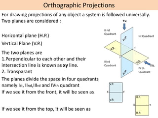
- 1. Orthographic Projections For drawing projections of any object a system is followed universally. Two planes are considered : Horizontal plane (H.P.) Vertical Plane (V.P.) The two planes are 1.Perpendicular to each other and their intersection line is known as xy line. 2. Transparant The planes divide the space in four quadrants namely Ist, IInd,IIIrd and IVth quadrant Ist Quadrant II nd Quadrant III rd Quadrant IV th Quadrant If we see it from the front, it will be seen as X Y V.P. V.P. F.V. If we see it from the top, it will be seen as T.V. X Y H.P. H.P.
- 2. NOTATIONS FOLLOWING NOTATIONS SHOULD BE FOLLOWED WHILE NAMEING DIFFERENT VIEWS IN ORTHOGRAPHIC PROJECTIONS. IT’S FRONT VIEW a’ 1’ OBJECT POINT A POINT 1 IT’S TOP VIEW a 1 IT’S SIDE VIEW a” 1”
- 3. FV & TV of a point always lie in the same vertical line FV of a point ‘P’ is represented by p’. It shows position of the point with respect to HP only. While drawing FV, XY line represents the HP and the plane of paper represents the VP. If the point P lies above HP, p’ lies above the XY line. If the point P lies in the HP, p’ lies on the XY line. If the point P lies below the HP, p’ lies below the XY line. TV of a point ‘P’ is represented by p. It shows position of the point with respect to VP only. While drawing TV, XY line represents the VP and the plane of paper represents the HP. If the point P lies in front of VP, p lies below the XY line. If the point P lies in the VP, p lies on the XY line. If the point P lies behind the VP, p lies above the XY line. Basic concepts for drawing projection of point FV does not give any information about position of the point w.r.t. VP TV does not give any information about position of the point w.r.t. HP X Y p’ X Y p’ X Y p’ X Y p X Y p X Y p
- 4. A point can have following nine positions When a point A is 35 mm above the H.P. and 20mm in front of the V.P. i.e. in first quadrant CASE I The point is in first Quadrant i.e. it is above the H.P. and in front of the V.P. Ist Quadrant II nd Quadrant III rd Quadrant VI th Quadrant a X Y a’ 35 20 8 Dimension should be placed 8 mm away from the projectors
- 5. When a point B is 35 mm above the H.P. and 20mm behind the V.P. i.e. in second quadrant X Y Ist Quadrant II nd Quadrant III rd Quadrant VI th Quadrant b X Y b’ 35 20 CASE II The point is in second Quadrant i.e. it is above the H.P. and behind the V.P.
- 6. When a point C is 35 mm below the H.P. and 20mm behind the V.P. i.e. in third quadrant Ist Quadrant II nd Quadrant III rd Quadrant VI th Quadrant c X Y c’ 35 20 CASE III The point is in third Quadrant i.e. it is below the H.P. and behind the V.P.
- 7. When a point D is 35 mm below the H.P. and 20mm in front of the V.P. i.e. in fourth quadrant X Y Ist Quadrant II nd Quadrant III rd Quadrant VI th Quadrant d X Y d’ 35 20 CASE IV The point is in fourth Quadrant i.e. it is below the H.P. and in front of the V.P.
- 8. When a point E is in the H.P. and 30mm in front of the V.P. i.e. between first and fourth quadrant Ist Quadrant II nd Quadrant III rd Quadrant VI th Quadrant e X Y e’ 30 CASE V The point is in the H.P. and in front of the V.P. i.e. it is between first and fourth quadrant
- 9. When a point F is in the V.P. and 30mm above the H.P. i.e. between first and second quadrant CASE VI The point is in the V.P. and above the H.P. i.e. it is between first and second quadrant Ist Quadrant II nd Quadrant III rd Quadrant VI th Quadrant f X Y f’ 30
- 10. When a point G is in the H.P. and 30mm behind the V.P. i.e. between second and third quadrant CASE VII The point is in the H.P. and behind the V.P. i.e. it is between second and third quadrant Ist Quadrant II nd Quadrant III rd Quadrant VI th Quadrant g X Y g’ 30
- 11. When a point H is in the V.P. and 30mm below the H.P. i.e. between third and fourth quadrant CASE VIII The point is in the V.P. and below the H.P. i.e. it is between third and fourth quadrant Ist Quadrant II nd Quadrant III rd Quadrant VI th Quadrant h X Y h’ 30
- 12. When a point J is in both H.P. and V.P. CASE IX Ist Quadrant II nd Quadrant III rd Quadrant VI th Quadrant j X Y j’
- 13. Draw Projection of following points on the same ground line keeping the projectors 25 mm apart. A: On the VP and 20 mm above the HP. B: 30 mm below the HP and 40 mm behind the VP. C: 50 mm above the HP and 25 mm behind the VP. D: On the HP and 15mm in front of the VP. E: 35mm above the HP and 50mm in front of the VP. F:40 mm below the HP and on the VP. G:35 mm behind the VP and on the HP. H: 45 mm below the HP and 20mm in front of the VP. J: on the HP and on the VP.
- 16. Problem: Projection of various points are given in the fig. State the position of each point with respect to principal planes 30 10 30 10 45 35 20 45 45 15 30 20 X Y a’ b’ c’ e’ f’ g’ d’ h’ a b h g c d e f