
Recommended
More Related Content
What's hot
What's hot (20)
Similar to Lasers: Characteristics, Components and Applications
Similar to Lasers: Characteristics, Components and Applications (20)
Recently uploaded
Recently uploaded (20)
Lasers: Characteristics, Components and Applications
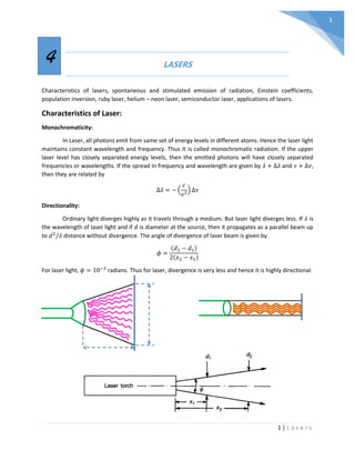
- 1. 1 | L a s e r s 1 LASERS Characteristics of lasers, spontaneous and stimulated emission of radiation, Einstein coefficients, population inversion, ruby laser, helium – neon laser, semiconductor laser, applications of lasers. Characteristics of Laser: Monochromaticity: In Laser, all photons emit from same set of energy levels in different atoms. Hence the laser light maintains constant wavelength and frequency. Thus it is called monochromatic radiation. If the upper laser level has closely separated energy levels, then the emitted photons will have closely separated frequencies or wavelengths. If the spread in frequency and wavelength are given by 𝜆 + Δ𝜆 and 𝜈 + Δ𝜈, then they are related by Δ𝜆 = − ( 𝑐 𝜈2 ) Δ𝜈 Directionality: Ordinary light diverges highly as it travels through a medium. But laser light diverges less. If 𝜆 is the wavelength of laser light and if 𝑑 is diameter at the source, then it propagates as a parallel beam up to 𝑑2 /𝜆 distance without divergence. The angle of divergence of laser beam is given by 𝜙 = (𝑑2 − 𝑑1) 2(𝑥2 − 𝑥1) For laser light, 𝜙 = 10−3 radians. Thus for laser, divergence is very less and hence it is highly directional. 4
- 2. 2 | L a s e r s 2 Coherence: In ordinary light source, light waves emit at random times in random directions. But in the stimulated emission process, all the photons will emit with definite phase relation with each other. This makes the laser beam highly coherent. There are two types of coherences. a. Temporal coherence: Two waves or two wave trains in a single wave are said to be in temporal coherence if they maintain a constant phase difference at a fixed point in space at different times. Coherence length (𝒍𝒄𝒐𝒉): The length up to which the light wave train maintains its phase predictable is called coherence length. Coherence time (𝒕𝒄𝒐𝒉): The time up to which the light wave train maintains its phase predictable is called coherence time. These two are related by 𝑙𝑐𝑜ℎ = 𝑐 𝑡𝑐𝑜ℎ Where 𝑐 is velocity of light. b. Spatial coherence: Two waves are said to be in spatial coherence if they maintain a constant phase difference at two different points in space at a given time. Here we study the phase relation between two waves perpendicular to the direction of motion of wave. Hence it is also called “Transverse coherence” or “Lateral (sideways) coherence”. Spatially and temporally coherent waves. The coherence length of laser light is of the order of a few meters to kilo meters. Intensity: As the laser beam is very narrow, almost all of its energy is highly concentrated into a small region. A typical laser output of 10−3 𝑊 can produce ∼ 1024 − 1034 𝑝ℎ𝑜𝑡𝑜𝑛𝑠/𝑚2 /𝑠. Whereas a black body at 1,000𝐾can produce only ∼ 1016 𝑝ℎ𝑜𝑡𝑜𝑛𝑠/𝑚2 /𝑠.
- 3. 3 | L a s e r s 3 Einstein coefficients: Atoms can be excited by supplying energy equal to the difference of any of its two energy levels. After a very short duration of time, atoms will come down to ground state by radiating energy. Stimulated absorption: If an atom is in the state 𝐸1, it can be raised to higher energy level 𝐸2 by the absorption of photon of energy ℎ𝜈 = 𝐸2 − 𝐸1. The probability of stimulated absorption from state 1 to state 2 is proportional to the energy density 𝑢(𝜈) of the incident radiation. 𝑃12 = 𝐵12 𝑢(𝜈) Here 𝐵12 is known as 𝐸𝑖𝑛𝑠𝑡𝑒𝑖𝑛′ 𝑠𝑐𝑜𝑒𝑓𝑓𝑖𝑐𝑖𝑒𝑛𝑡 𝑜𝑓 𝑠𝑡𝑖𝑚𝑢𝑙𝑎𝑡𝑒𝑑 𝑎𝑏𝑠𝑜𝑟𝑝𝑡𝑖𝑜𝑛. Spontaneous emission: If the atom is initially in an excited state 𝐸2, it can come down to lower state 𝐸1 on its own by emitting a photon of energy ℎ𝜈 = 𝐸2 − 𝐸1. This is known as spontaneous emission. The probability of spontaneous emission depends only on the properties of states 1 and 2. 𝑃21 ′ = 𝐴21 Here 𝐴21 is known as 𝐸𝑖𝑛𝑠𝑡𝑒𝑖𝑛′ 𝑠 𝑐𝑜𝑒𝑓𝑓𝑖𝑐𝑖𝑒𝑛𝑡 𝑜𝑓 𝑠𝑝𝑜𝑛𝑡𝑎𝑛𝑒𝑜𝑢𝑠 𝑒𝑚𝑖𝑠𝑠𝑖𝑜𝑛. Stimulated emission: Einstein was the first to identify the possibility of induced or stimulated emission. If a photon of energy ℎ𝜈 = 𝐸2 − 𝐸1 interacts with an atom which is already in the excited state 𝐸2, it will induce the
- 4. 4 | L a s e r s 4 transition from the state 𝐸2 to 𝐸1. This is known as stimulated emission. The probability of this stimulated emission depends on the energy density 𝑢(𝜈) of the incident radiation. 𝑃21 ′′ = 𝐵21𝑢(𝜈) The total probability of emission transition from 𝐸2 to 𝐸1 is given by 𝑃21 = 𝑃21 ′ + 𝑃21 ′′ = 𝐴21 + 𝐵21𝑢(𝜈) Relation between Einstein coefficients: Let there are 𝑁1 number of atoms in the ground state 1 and 𝑁2 number of atoms in the excited state 2. Then the probability of absorption transition from state 1 to 2 is given by 𝑁1𝑃12 = 𝑁1𝐵12𝑢(𝜈) The total probability of emission transition from state 2 to 1 is given by 𝑁2𝑃21 = 𝑁2[𝐴21 + 𝐵21𝑢(𝜈)] At thermal equilibrium, the absorption probability and emission probability becomes equal. Thus we can write, 𝑁1𝑃12 = 𝑁2𝑃21 ⇒ 𝑁1𝐵12𝑢(𝜈) = 𝑁2[𝐴21 + 𝐵21𝑢(𝜈)] ⇒ 𝑁1𝐵12𝑢(𝜈) − 𝑁2𝐵21𝑢(𝜈) = 𝑁2𝐴21 ⇒ 𝑢(𝜈) = 𝑁2𝐴21 𝑁1𝐵12 − 𝑁2𝐵21 ⇒ 𝑢(𝜈) = 𝐴21 𝑁1 𝑁2 𝐵12 − 𝐵21 From Boltzmann’s distribution law, we get 𝑁1 𝑁2 = 𝑒−𝐸1/𝑘𝑇 𝑒−𝐸2/𝑘𝑇 = 𝑒 (𝐸2−𝐸1)/𝑘𝑇 = 𝑒ℎ𝜈/𝑘𝑇 ⇒ 𝑢(𝜈) = 𝐴21 𝐵12𝑒ℎ𝜈/𝑘𝑇 − 𝐵21 = 𝐴21 𝐵21 [ 𝐵12 𝐵21 𝑒ℎ𝜈/𝑘𝑇 − 1] From Plank’s radiation law, we have 𝑢(𝜈) = 8𝜋ℎ𝜈3 𝑐3 1 𝑒ℎ𝜈/𝑘𝑇 − 1 Comparing the above two equations, one can get 𝐵12 = 𝐵21
- 5. 5 | L a s e r s 5 𝐴21 𝐵21 = 8𝜋ℎ𝜈3 𝑐3 The above two equations give the relation between the three Einstein coefficients. Population inversion: Consider a two level system with energies 𝐸1 and 𝐸2 containing 𝑁1 and 𝑁2number of particles respectively. If 𝑁0be the total number of particles, then the total number of particles in the states 𝐸1 and 𝐸2 are given by 𝑁1 = 𝑁0 𝑒−𝐸1/𝑘𝑇 𝑁2 = 𝑁0 𝑒−𝐸2/𝑘𝑇 Since 𝐸2 > 𝐸1 ⇒ 𝑁2 < 𝑁1 Ie; in general lower energy levels will have higher population. The situation where the population of lower energy level is more than the energy of the higher energy level is known as population inversion. The process of increasing the population of higher energy level compared to the lower energy level is known as pumping. Components of laser: Any laser system contains three major components as shown in the figure. 1. Energy source: To get the laser action, we must have population inversion in the system. For that atoms must be excited to higher energy levels. This energy source can be obtained from any optical or electrical or chemical process. This portion of the laser system acts as the pumping mechanism which is essential for population inversion. 2. Active medium: This is the medium where stimulated emission takes place. After taking energy from the source, atoms and molecules will get excited. In the de-excitation process, stimulated emission takes place which gives laser light. Depending on the type of active medium, we have solid state, liquid state, gaseous and semiconductor lasers.
- 6. 6 | L a s e r s 6 3. Optical cavity or resonator: The active medium is enclosed between two reflecting surfaces. Out of the two, one is perfectly reflecting and the other one is partially reflecting. Depending on the active medium, there are mirrors, Brewster prisms that are used as resonance cavity. In semiconductor laser the end surfaces of the active medium itself acts as a resonator after polishing. In an active medium, we can’t get sufficient intensity laser light in one pass and we can’t maintain population inversion uniformly if the length of the active medium increases. Resonance cavity helps in overcoming this difficulty by repeated reflections. Thus resonance cavity effectively (indirectly) increases the length of the active medium. The length of the cavity must be an integer multiple of 𝜆/2 for proper constructive interference and amplification. Since there are two reflecting surfaces, the total phase difference introduced will be 𝜋 + 𝜋 = 2𝜋. This can be considered as zero. Ruby Laser: Ruby laser is the first laser developed in 1960. The major parts of ruby laser are as explained. 1. Active medium: In ruby laser the active medium is the Ruby crystal cut in the shape of a rod. The ruby crystal is an 𝐴𝑙2𝑂3 crystal with 0.05% of 𝐴𝑙+3 ions are replaced by 𝐶𝑟+3 ions. Here the energy levels of 𝐶𝑟+3 ions have metastable states, where population inversion occurs and lasing action takes place. 2. Energy source: The energy source consists of a xenon flash lamp which emits green light at 5500Å. The xenon tube lamp is wrapped around the ruby rod. The output of xenon lamp is in the form of millisecond pulses and power is a few megawatts. Due to this high power output, the ruby rod may get heated up. Hence the whole arrangement is placed in a liquid nitrogen bath to keep the system cool. Now a days the lamps are enclosed by concave mirrors to increase the light exposure to ruby rod. 3. The resonance cavity: The resonance cavity is obtained by polishing the ends of ruby rod. The ends are made optically parallel and then a fully reflecting mirror is placed at one end and another partially reflecting mirror is placed at the other end.
- 7. 7 | L a s e r s 7 4. The laser action: The energy level diagram of 𝐶𝑟+3 ion is as shown in the below figure. It is a three level laser system. The chromium ion absorbs green light (5500Å) from xenon flash or any blue light (4000Å) from alternative sources and goes to excited states 𝑇2 and 𝑇1 respectively. They give a part of the energy to the crystal in the form of heat and reach a meta- stable state 𝐸 2 . Thus the number of ions in the ground state keeps on decreasing due to pumping and number of ions in the metastable state keeps on increasing due to long life time. Finally population inversion is established between the metastable and ground state. When any ion from this metastable state comes to ground state spontaneously, it will start further stimulated emissions. The laser light has two wavelengths 6943Å and 6929Å. Out of these two, 6943Å only gets amplified by the resonance cavity as the length of the cavity is selected suitable to that. 𝑇 4 1 𝑇 4 2 𝐸 2 4000Å 5500Å 6943Å 6929Å
- 8. 8 | L a s e r s 8 Disadvantages: 1. Since the lower laser level is connected to ground state, one need to excite more than 50% of the ions in a short span of time to achieve population inversion. This requires very high pumping energies. 2. Since more than 50% of ions will be in the excited state, one has to wait till they de-excite for next series of laser action to take place. Thus the laser output is pulsative. 3. Since the lower laser level is connected to ground state, there is a possibility of self-absorption which reduces the output intensity. Due to this, the efficiency of Ruby laser is about 1%. Advantages: 1. Though it has very low efficiency, the output power is very high. Thus it is used for diamond cutting and welding also. 2. The pulsed output has some special applications like holography. 3. Since it is a solid state deice, it has very low maintenance cost and can be used roughly also. Applications: 1. Ruby lasers are used as pumping system for dye laser. 2. Before the discovery of 𝑁𝑑 − 𝑌𝐴𝐺 laser, ruby laser was used for tattoo and hair removal. He-Ne laser This is a low power, continuous wave laser developed in the year 1962 after the discovery of ruby laser. Active medium: Here the active medium is a mixture of helium and neon gases in the ratio 10: 1 filled in a quartz tube at a pressure of 0.1𝑚𝑚 of mercury. Here Helium excites first and supplies energy to Neon, where population inversion takes place. Energy source: The gases are excited by using electric discharge either by dc current or by rf ac current. Time (in milliseconds)
- 9. 9 | L a s e r s 9 Resonance cavity: The resonance cavity can be obtained by using two optically parallel mirrors on the either side of the tube. Or some times Brewster prisms are used for proper polarization, as high pressures and electric discharges in the tube may damage the mirrors. Laser action: The energy level diagram of helium and neon are as shown below.
- 10. 10 | L a s e r s 10 This is an example of four level laser system. The energy levels of Helium are labeled as follows. 1𝑠2 (↑ ↓) → 11 𝑆0 1𝑠1 2𝑠1 (↑ ↑) → 2 𝑆 3 1 1𝑠1 2𝑠1 (↑ ↓) → 2 𝑆 1 0 The energy levels of Neon atom are The 2 𝑆 3 1 level and 2 𝑆 1 0 are meta-stable states in Helium. The atoms excited to these states will de-exite only by collision. These two excited levels lie at around 20.61𝑒𝑉. This energy will be transferred to Neon and neon atoms which go to 3𝑠 or 2𝑠 states that lie at around 20.66𝑒𝑉. The difference in energy will come through collision. These two levels of Neon are again metastable states. There are three possible laser transitions from these two metastable states. 3𝑠 → 2𝑝 6328Å 2𝑠 → 2𝑝 11523Å (𝐼𝑅) 3𝑠 → 3𝑝 33900Å (𝐼𝑅) Here the 6328Å transition only lies in the visible region. This can be enhanced by choosing the proper length of resonance cavity. From 2𝑠 state, the atoms take a rapid transition to 1𝑠 state which is again a metastable state. From there atoms may excite to 2𝑠 state again by taking electric field energy. This increases the population in 2𝑝 state and population inversion condition fails. To avoid this, the tube is made narrow and gas is filled at high pressures. With that, separation between atoms reduce, number of collisions increase and atoms will de- exite to ground state from 1𝑠. Advantages: 1. High powers are not necessary for pumping. This is because laser levels are not connected to ground state, keeping a very few atoms in the metastable state will satisfy the condition for population inversion. 2. This is a continuous laser. Since population inversion is achieved with very low number of atoms in metastable state, we don’t need to wait for them for further laser transitions. 3. Since it is a low power device, its maintenance cost is very low. 4. Disadvantages:
- 11. 11 | L a s e r s 11 1. High power outputs cannot be achieved even by increasing electric charge or increasing length of the tube. Because it will enhance the 33900Å transition which depopulate the upper laser level and condition for population inversion fails. Applicatiopns: 1. It is used in integrated bar code readers. 2. It is used in laser surgery and laser cutting. 3. It is used in surveying for high accuracy, due to its narrow beam width. Semiconductor laser: In ordinary 𝑝 − 𝑛 junction diode, the Fermi level lies within the band gap region. But if the doping concentrations increase, the depletion region width reduces and also the donor levels enter the conduction band and acceptor levels enter the valence band. Thus in this case, the Fermi level enters the conduction band and valence band on the either side of the junction. When a forward bios (𝑉𝑓) is applied across the junction, conduction starts in the diode, though some kink still remains in the bands at the junction. This happens if the following condition is satisfied. 𝐸𝑔 < 𝑒𝑉𝑓 = ℎ𝜈 < 𝐸𝐹𝑐 − 𝐸𝐹𝑣 In this situation charge carriers will slow down at the junction satisfying the condition for population inversion. If the chosen semiconductor material has direct band gap, then the excited electrons will recombine with the holes in the valence band releasing a photon. If the band gap is in direct, a collision is also required to release a phonon for de-excitation. Usually gallium arsenide (𝐺𝑎𝐴𝑠) is used for this purpose as it has direct band gap.
- 12. 12 | L a s e r s 12 This the working principle of light emitting diode (LED). If a resonance cavity is also made, photons in phase will get amplified releasing laser light. 𝐺𝑎𝐴𝑠 has sufficient refractive index that itself acts as a reflecting surface. Hence no additional mirrors are necessary for diode laser cavity. The cavity is made by cleaving the semiconductor in the direction perpendicular to the crystal planes and polishing the crystal planes optically parallel. Advantages: It is a low power, high efficient, compact and low maintenance deice. Disadvantages: The beam width is very high compared to other traditional lasers. The coherence length is low compared to other traditional lasers. Applications: Used in barcode readers. Used in CD, DVD players. Applications of lasers: 1. It is used in industries for high precision cutting, welding and drilling. 2. It is also used for micro hole drilling and cutting where traditional instruments fail. 3. In semiconducting industry, lasers are used for drawing lines on circuit boards, soldering, precisely cutting resistance materials (as accuracy in resistance is decided by the size of the material). 4. In medical field, lasers are used to clear blocks in heart, used for cataract removal, for the removal of tattoos, unwanted marks, to remove stones in bladder, and kidney. 5. Lasers are major sources of light in optical communication. 6. In scientific research, lasers are used to study the optical properties of materials. 7. In civil engineering, they are used while surveying for accurate distance measurement. 8. In defense, lasers are used to guide missiles, and high intensity lasers beams are also used as death rays.
- 13. 13 | L a s e r s 13 POLARIZATION The phenomenon in which the direction of vibration of electric field vector of light rays is restricted to a particular direction is called polarization. When light passes through tourmaline crystal, the emergent beam becomes plane polarized whose direction of oscillation of electric field vector is parallel to the optic axis of the crystal. If another crystal is placed in the direction of the polarized light and if the optic axis is parallel to the direction of polarization, then the light will be passed through. If the optic axis is perpendicular to the direction of polarization, then light will be blocked. Plane polarized light: If the direction of oscillation of electric field vector of light is restricted to a plane, then it is called a plane polarized light. Circularly polarized light: If the electric field vector of light ray traces a circular path during the propagation, then it is called circularly polarized light. 5
- 14. 14 | L a s e r s 14 Depending on the direction of rotation, there will be right circularly polarized light and left circularly polarized light. Right circularly polarized light Left circularly polarized light Elliptically polarized light: If the electric field vector of light traces elliptical path, then it is called elliptically polarized light. Depending on the direction of rotation, there are right elliptically polarized light and left elliptically polarized light. Polarization by reflection (Brewster’s law) It was Malus who observed that when unpolarized light reflects from any surface, it is plane polarized. Further it was Brewster who identified that when light incidents at a particular angle, the reflected light is completely plane polarized. Brewster also identified that tangent of that particular angle of incidence is equal to refractive index of the material. Thus
- 15. 15 | L a s e r s 15 𝜇 = tan 𝑖𝑝 = sin 𝑖𝑝 cos 𝑖𝑝 From Snell’s law we know that 𝜇 = sin 𝑖𝑝 sin 𝑟 From the above two equations, cos 𝑖𝑝 = sin𝑟 ⇒ sin(90° − 𝑖𝑝) = sin𝑟 ⇒ 90° − 𝑖𝑝 = 𝑟 ⇒ 𝑖𝑝 + 𝑟 = 90° From the above figure, ∠𝐴𝑂𝑅 + ∠𝑅𝑂𝑇 + ∠𝑇𝑂𝐵 = 180° ⇒ 𝑖𝑝 + ∠𝑅𝑂𝑇 + 𝑟 = 180° ⇒ ∠𝑅𝑂𝑇 = 90° Ie; when the light incidents at Brewster’s angle, the angle between reflected ray and refracted ray will be equal to 90°.
- 16. 16 | L a s e r s 16 Polarization by refraction/selective absorption (Malus law) When unpolarized light falls on certain crystals like tourmaline, the emergent light is plane polarized with electric field vibrations parallel to the optic axis of the crystal. If another crystal is placed in the direction of the polarized light and if the optic axis is parallel to the direction of polarization, then the light will be passed through. If the optic axis is perpendicular to the direction of polarization, then light will be blocked. Here the first crystal is called the polarizer and the second one is called the analyzer. If 𝜃 is the angle between the optic axes of polarizer and analyzer, then the intensity of light emerging out of analyzer is proportional to the square of the cosine of the angle between the optic axes of polarizer and analyzer. If 𝐼0 be the intensity of light after passing through the polarizer, and if 𝜃 be the angle between the optic axes of polarizer and analyzer, then the intensity of light emerging out of analyzer is given by 𝐼 = 𝐼0 cos2 𝜃 This is the Malus law.
- 17. 17 | L a s e r s 17 Double refraction/Birefringence: When a beam of unpolarized light falls on an anisotropic crystal such as calcite or quartz, the light will be polarized and also split into two plane polarized rays. This phenomenon is known as double refraction or birefringence. The two rays are known as 𝑂𝑟𝑑𝑖𝑛𝑎𝑟𝑦 − 𝑟𝑎𝑦 𝑜𝑟 O-ray with electric field vibrations perpendicular to the plane of paper and the 𝑒𝑥𝑡𝑟𝑎𝑜𝑟𝑑𝑖𝑛𝑎𝑟𝑦 − 𝑟𝑎𝑦 or E-ray with electric field vibrations on the plane of the paper. Optic axis: Any line passing through the blunt corners of a birefringent crystal is known as optic axis. Any line parallel to that is also known as optic axis. Plane of polarization: The plane perpendicular to the direction of motion and the direction of oscillations of electric field vector is known as plane of polarization.
- 18. 18 | L a s e r s 18 Principal section: Any plane containing optic axis and perpendicular to a pair of opposite faces of the crystal is known as the principal section. The principal section of calcite is a parallelogram with angles 71° and 109°. The refractive index of O-ray and E-ray in calcite is given by 𝜇𝑜 = sin 𝑖 sin𝑟1 , 𝜇𝑒 = sin 𝑖 sin 𝑟2 Positive crystal and negative crystal: A birefringent crystal in which ordinary ray travels slower than the extraordinary ray is known as negative crystal. Eg: Calcite. For this crystal 𝑣𝑜 < 𝑣𝑒 or 𝜇𝑜 > 𝜇𝑒. A birefringent crystal in which ordinary ray travels faster than the extraordinary ray is known as positive crystal. Eg: Quartz. For this crystal 𝑣𝑜 > 𝑣𝑒 or 𝜇𝑜 < 𝜇𝑒 Along the optic axis of the crystal, both rays will travel with equal velocity. Hence the wave front of O-ray and E-ray in both positive and negative crystal are as shown in the picture. Nicol prism: Nicol prism is a device made from calcite crystal used to produce and analyze plane polarized light. It is designed in such a way that it transmits extraordinary ray and blocks the ordinary ray. It is developed by a Schotch physicist William Nicol in 1828.
- 19. 19 | L a s e r s 19 Construction: The principal section of the calcite crystal is cut into two along the optic axis and then joined with Canada blasm, a gum. The faces of the crystal are polished again to make the angle of the parallelogram from 71° to 68°. The refractive index of ordinary ray and extra ordinary ray in calcite for sodium yellow light 5893Å is given by 𝜇𝑜 = 1.6584 𝜇𝑒 = 1.4864 The refractive index if Canada blasm is given by 𝜇 = 1.55 Thus Canada blasm acts as denser medium for E-ray and rarer medium for O-ray. If the angle of incidence is managed to be more than the critical angle of 𝑂 − 𝑟𝑎𝑦, then it will be totally internally reflected. The critical angle of O-ray is given by 𝜃𝑐 = sin−1 [ 1.55 1.6584 ] = 69.2° To make angle of incidence on Canada blasm more than this critical angle, the angle of calcite is grounded from 71° to 68° and length is made thrice the height of the crystal. Thus nicol prism can be used as polarizer and analyzer.
- 20. 20 | L a s e r s 20 Quarter wave plate and Half wave plate:
- 21. 21 | L a s e r s 21 Fibre optics Optical fibre works on the principle of total internal reflection. Ie, when light travels from a denser medium ( high refractive index medium) to rarer medium ( low refractive index medium), and if the angle of incidence is more than critical angle, light will be totally internally reflected into denser medium. The major components of optical fibre are as follows. Core: it is a high refractive index material in which the light transmits. It is made up of glass or plastic or a mixture of both. Cladding: it is a low refractive index material which covers the core material and ensures total internal reflection. It is also made up of glass or plastic or mixture of both. Protecting layer: the entire core and cladding structure is covered with rubber or polymer material to protect it from surrounding environmental effects. Classification of optical fibre: Depending on the material of core and cladding, optical fibres are classified into two categories. Glass and plastic. If it is made of glass (SiO2), GeO2 also will be added to core to increase its refractive index. In that case, core will be of pure SiO2. If it is made up of plastic, proper materials are chosen to maintain the required refractive index difference. Glass fibres are costly, difficult to manufacture but are highly notice proof and lossless. Whereas, plastic fibres are easy to manufacture, cheap but highly noisy and lossy channels to transmit information. Depending on the number of modes of wavelengths, the cable allows, the optical fibres are classified into two. Single mode and multi mode. Single mode fibre allows only one wavelength, whereas multimode fibre allows more than one wavelength of light to travel. The core of single mode fibre is narrow, where as for multimode fibre it is wider.
- 22. 22 | L a s e r s 22 Notice levels and losses are very low in single mode fibre where as they are very high in the multimode fibre due to the presence of multiple wavelengths. Single mode fibres can transmit information up to a few kilometers without much loss, whereas multimode fibres could transmit only a few meters without much loss of information. Single mode fibres are used for long distance communication channels, whereas multimode fibres are used for LAN ( local area network) communication. Depending on the refractive index of core material, optical fibres are classified into two. Step index and graded index. In step index fibre, refractive index remains constant throughout the core and drops suddenly at the core cladding boundary. In graded index fibre, refractive index reduces gradually from the centre of the core. In the case of multimode step index fibre, all waves will get reflected at the core and cladding boundary but at different locations or different angles of incidence. In multimode graded index fibre, different modes will reflect at different distances from the center of the core. In the case of step index fibre, different modes will travel with different velocities whereas in graded index fibre all modes will travel with same velocity. In the case of step index fibres, noise levels are high due to velocity differences between different modes. Whereas in graded index fibre, noise levels are less as all modes will travel with same velocity.
- 23. 23 | L a s e r s 23
- 24. 24 | L a s e r s 24
- 25. 25 | L a s e r s 25
- 26. 26 | L a s e r s 26
- 27. 27 | L a s e r s 27
- 28. 28 | L a s e r s 28