2. 2
Contents
Selection of the Fenner Belt Drive Components (Pages 3-7)
Selection of the HPC Gears (Pages 7-12)
Shaft Loading (Pages 12-20)
Key Size and Keyways (Pages 20-21)
BearingSelection (Pages 21-22)
Limits and Fits (Pages )
Design Drawings (Pages )
Parts
Assembly
Appendix
Input Shaft LoadingForm
Design Summary Form
3. 3
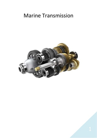
As a group we will bedesigninga transmission systemto for fill the requirements of our brief. This report will
take you through the steps in which we took in order to come up with an economical design.We will cover the
following;Pulley and Belt selection,Gear Selection, Shaft design,Key and Keyways, Bearing and complete
drawingof the system. We had been given the followingrequirements:
Gear
Ratio
Input
Speed
(rpm)
Input
Power
(kW)
Alternator
Power
(kW)
Alternator
Speed
(rpm)
Degrees Minimum
A (mm)
Minimum
B (mm)
Minimum
C (mm)
3 1050 25 7 1200 60 60 45 45
The followingassumptions havebeen made throughout the designingprocess:
3 cylinder engine
20 degree involute tooth profile
Pinion minimumof 20 teeth
Key material has a directyield stress of 300MPa
Definingthe length of the key, a safety factor of 2.0 must be used to the yield strength
Centre distanceof pulleys must be between 600 and 800 mm
Tc is equal to zero
Contact angle is closeenough to 180o
Belt factor is 1.0
Tequiv has a safety factor of 2.5 on yield in shear
Transmission isto lastfor 15 years, 250 days a year and on average of 6 hours a day
Maximum yield stress in shear is 0.5 of the directyield stress
Direct yield stress is 0.6 of the ultimate tensilestrength (to be used in sizingthe shaft)
Selection of the Fenner Belt Drive Components
Visitthe followingsite;http://www.fptgroup.com/. Click on Belt Drives and open the pdf document “Fenner
Friction Belts”. Go to page 39 and this gives you a step-by-step on Belt and Pulley selection. These are the
followingsteps that we followed:
Speed Ratio
Input Speed / Alternator Speed = Speed Ratio
1200 / 1050 = 1.14
Service Factor
Given that we requirea lightduty startand the 3 cylinder engine is needed to run for 6 hours a day, we can
find the servicefactor.
Service Factor = 1.1 x 1.00 =1.1
We multiply by 1.00 due to the speed increaseratio.
Figure 1
Figure 2
4. 4
Design Power
Alternator Power x ServiceFactor = Design Power.
7 x 1.1 = 7.7 kW
Belt Section
Given that we know the faster shaftto be 1200rpm and the design power to be 7.7kW. Readingof the table
gives us a SPZ belt.
Minimum Pulley
Usingthe same information as previously wedetermined the minimum pulley diameter is 95mm.
Pulley Pitch Diameters
Given that our speed ratio is 1.14,the pitch diameter of pulleys of the Driver is 140mm and of the driven is
160mm.
Figure 3
Figure 4
5. 5
Belt Length, Centre Distance and Correction Factor
Restricted bounds have been given therefore the centre distanceneeds to fall between 600mm and 800mm.
Usingthe same information as before, continue reading;the followingcentre distances fall in thebounds
664mm with a combined arc and belt length correction factor of 1.00 and 764mm with a correction factor of
1.05. We chose764mm givinga belt length of 2000mm for the reason that the belt has a higher lifespan than
a shorter belt. Trip rate was also calculated to show that itdidn’t exceed 6/8 trips becauseit was given as a
guide for ratios lower than 1.3;
(0.0524 x small pulley pitch diameter x fastshaft) / Length of belt = Trip Rate.
(0.0524 x 140 x 1200) / 2000 = 4.4016
Basic Power per Belt
Given that we know the faster shaftto be 1200rpm and the small pulley pitch diameter to be 140mm. We
determined the Basic Power per Belt is 3.72kW and noting that the belt speed is 10ms -1.
Figure 5
6. 6
Speed Ratio Power Increment
Followingthe fast shaftto having1200rpmand given that the speed ratio is 1.14 the speed ratio power
increment is 0.08kW.
Corrected Power per Belt
(Speed Ratio Power Increment + Basic Power per Belt) x Correction Factor = Corrected Power per Belt
(0.08 + 3.72) x 1.05 = 3.99
Number of Belts required
Design Power / Corrected Power per Belt = Number of Belts required
7.7 / 3.99 = 1.929825
Therefore we require 2 SPZ belts.
Bore sizes
We decided on type 1 pulley so readingoff the table on page 63 lead to the followingpulley max bores;
For the driver pulley of 140mm
42mm
For the driven pulley of 160mm
42mm
In conclusion wehave determined that we require2 belts and 2 pulleys;one of which is 140mm with a
maximum bore sizeof 42mm and the other of 160mm with the same maximum bore size. The material of the
Figure 6
Figure 7
7. 7
pulley is stainlesssteel as itis typical used in marineapplications. The pulleys havethe followingcatalogue
codes; 031Z0201 and 031Z0221.
Selection of the HPC Gear
Visitthe followingsitehttp://www.hpcgears.com/. We created a excel document to present the following
information so that we could determine the most viablegear set. For the purpose of this,the brief asked us to
use spur gears and start atmodule 3, so by clickingon Spur Gears select the type of gear “Metric (MOD)” and
size“3.0 MOD”. This was used to determine which gears were available;the brief asked us to start at 20 teeth,
so from there we went up in the number of teeth. But we had to make surethat it corresponded with the ratio
in the brief. Those gears that didn’t have 3 times the number of teeth were eliminated.The followingmodules
had the availablegears:
MOD 3
20
21
24
25
26
28
30
32
MOD 4
20
21
22
23
24
MOD 5
20
Note that the above gears arepossiblepinionsand there arestandard and heavy-duty versions of the gears.
On the cataloguepage on the top it shows the availablematerialsfor the gears. For standard gears the
followingmaterials whereavailable:
Steel 214M15
Steel 045M10
Brass
Tufnol
Derlin
The followingwere availablefor heavy-duty gears:
817M40 (En24)
655M13 (En 36)
080M40 (En8)
On the same siteclick on “Technical”,open the pdf document “General”. We created tabs to separate
different material thatwe analysed,the followingmaterialswere used under the followingtabs:
Standard
o 045M10 (EN32A)
Heavy-Duty
o 817M40 (EN24)
Standard Hardened
o 045M10 (EN32A) CaseHardened
Figure 8
8. 8
Heavy-Duty Hardened
o 655M13 (EN36) CaseHardened
Usingfigure 9 we could find the values of Sc and Sb.
Now open the “Gearing” pdf document. The followinginformation can befound on this document:
Speed factor for strength (Xb)
Speed factor for wear (Xc)
Strength factor (Y)
Zone factor (Z)
Xb and Xc can be found by usingfigures 10 and 11 but requires interpolation. We know the input speed to be
1050rpmand the ratio is 3:1 the pinions shaftspeed is 3150rpm.We also knowthat the system will run for 6
hours a day, usingthis information singlevalueinterpolation can beused.
Figure 9
Figure 10
9. 9
Y and Z can we found by usingfigures 12 and 13. Given that we know all availablegears for the pinion and the
main gear we can use two-value interpolation to find these values.
Figure 11
Figure 12
Figure 13
10. 10
The followingvalues arestill needed to be found in order to find which gear set is best:
Face width (F)
DP
Pitch factor (K)
Face width can be found on top of the cataloguepages,figure 14 shows the one for MOD 3 Standard.The
values arein metric and they need to be in imperial so they needed to be converted to inches.
DP can be easy was calculated usingthe followingformula:
Pitch Factor was calculated usingthe followingformula:
= K
After all thedata was collected Wear and Strength were calculated so that there were comparablevalues.
Wear equation:
Strength Equation:
Once they were calculated we dividethe wear and strength by the number of teeth for each of the pinions.Ft
was also calculated and inputted into the collection of data and this is to be used in Shaft Loading.
The excel document shows all the data for the pinion.
Figure 15 Standard Gears data
Figure 14
11. 11
Figure 16 Heavy-Duty Gears data
Figure 17 Standard Case Hardened
Figure 18 Heavy-Duty CaseHardened
Now that we had the Wear per tooth and Strength per tooth we were ableto produce graphs for each of the
modules. The followinggraphs showed intersections:
Number ofteeth
Strengthpertooth&
Wearpertooth
Figure 19
MOD 4 Standard Case Hardened
12. 12
The point of intersection shows us the optimum number of teeth and strength per tooth. We choseto choose
from MOD 4 standard casehardened because itwould be leastexpensive. Now that we found the optimum
strength per tooth we then multiplied itby the optimum number of teeth. Givi ngoptimum design strength, we
chose the gear that was above the optimum design strength to ensure that it was capableto withstand the
forces. Then we decided to go for 20 teeth because it was the leastexpensive and it still fulfilled the
requirements. As a further precaution we had to check that Ft was below the strength of the gear.
Shaft Loading
Firstly we took each part and their forces and broken them down into their verti cal and horizontal
components.
Pulley Forces Calculations
Given that we know the small pulley diameter to be 140mm, usingthe Fenner catalogueshown previously in
the Selection of the Fenner Belt DriveComponents section. It gives us P to be 25N.
TS = 16P = 16 x 25 = 400 N
TD = 2TS sin (/2) n, is closeto 180o
So sin (180/2) = 1
Number ofteeth
Strengthpertooth&
Wearpertooth
Figure 20
MOD 4 Heavy-DutyCase Hardened
Figure 21
13. 13
TD = 2TSn = 2 x 400 x 2 = 1600 N
TV = 1600sin60 =1385.640646 N
TH = 1600cos60 =800 N
Gear Forces Calculations
Ft = 1804.477817 N
FV = 1804.477817sin20 =617.1677616 N
FH = 1804.477817cos20 =1695.654489 N
These are the component forces of Ft.
Gear Shaft - Vertical
Gear Torque Calculations
(1050 x 2) / 60 = 109.955743
T = /P
25000 / 109.955743 = 227.36 Nm
Figure 22
Figure 23All distances arein mm
Clockwiseis positive
16. 16
Gear Resultant Bending Diagram
902 + 522 = 104 Nm
602 + 16.42 = 62 Nm
Nm
104
62
x
T B1 F B2
Teq = M2 + T2
Teq = 1042 + 2272 = 250 Nm
Teq = 622 + 2272 = 235 Nm
max = Yield Strength x 0.6
Alloy Steel = 600 MN/m2
Low Carbon Steel = 420 MN/m2
Mild Steel = 308 MN/m2
Stainless Steel = 700 MN/m2
SF = 2.5
d = 1.1 3 16 x Teq x SF
x max
Alloy Steel
1.1 3 16 x 250 x 2.5 = 22.8 mm
x 0.6 x 600 x 106
Low Carbon Steel
1.1 3 16 x 250 x 2.5 = 25.7 mm
x 0.6 x 420 x 106
Mild Steel
1.1 3 16 x 250 x 2.5 = 28.5 mm
x 0.6 x 308 x 106
Stainless Steel
1.1 3 16 x 250 x 2.5 = 21.7 mm
x 0.6 x 700 x 106
The Above diameters are the minimum if the shaftis to be made from the different materials.
19. 19
Pinion Torque Calculations
(3150 x 2) / 60 = 329.867229
T = /P
25000 / 329.867229 = 75.79 Nm
Resultant Bending Diagram
15.42 + 42.42 = 45 Nm
Nm 45
x
B1 F B2
Teq = M2 + T2
Teq = 452 + 75.792 = 88 Nm
d = 1.1 3 16 x Teq x SF
x max
Alloy Steel
1.1 3 16 x 88 x 2.5 = 16.1 mm
x 0.6 x 600 x 106
Low Carbon Steel
1.1 3 16 x 88 x 2.5 = 18.1 mm
x 0.6 x 420 x 106
Mild Steel
1.1 3 16 x 88 x 2.5 = 20.1 mm
x 0.6 x 308 x 106
Stainless Steel
1.1 3 16 x 88 x 2.5 = 15.3 mm
x 0.6 x 700 x 106
The Above diameters are the minimum if the shaftis to be made from the different materials.
20. 20
All calculated arediameters have been rounded to the nearest upper 0.1 because the diameter cannot be
lower than the actual calculated value. So in conclusion wehave multiplied the yield strength of the material
by 0.6 as requested in the brief. This led us to determine minimum diameters for the gear and pinion shaftfor
the followingmaterials;Low carbon steel, mild steel, alloy steel and stainlesssteel.We have chosen to use
alloy steel for the reason that itis the second cheapest out of the four of them. Also it has the second smallest
diameter, so that we can reduce material use and it’s the most ideal for the availablesizes there are for the
gears and the bearings. This gives us the followingminimumdiameters of 22.8mm and 16.1 for the gear and
pinion shaft.
Key Size and Keyways
We have chosen to use a flatkey. We used figure42 to give us the dimensions of the key and keyway.
As for the dimension of the gear shaftis 30mm and for the pinion shaftis 25mm, the followingdimensions are
for the key and the keyway (width x depth):
Pinion Shaft
Key 6 x 6
Keyway 6 x 2.8
Gear Shaft
Key 8 x 7
Keyway 8 x 3.3
We then defined L with strength calculation:
Direct Yield Strength = 300 MN/m2
A safety factor of 2.0 is applied to the yield strength.
Lengths of the keys
Equation:
L = ( 2 x T ) / ( b x D x Ss )
Gear key
L = ( 2 x 227 ) / ( 8 x 10-3 x 25 x 10-3 x 0.5 x 300 x 106 ) = 15.13 mm = 15.2 mm
Pinion key
L = ( 2 x 75.79 ) / ( 6 x 10-3 x 20 x 10-3 x 0.5 x 300 x 106 ) = 8.421 mm = 8.5 mm
These are the required length of keys in order to overcome the failuredue to shear forces.
21. 21
Pinion Shaft
T = (60 x P) / (2 x n)
(60 x 25000) / (2 x 3150) = 75.79
L > (4T x N) / (Sy x D x b)
L = (4 x 75.79 x 2) / (300 x 106 (0.025 x 0.006)) = 0.0134738 x 1000 = 13.5mm
Gear Shaft
T = (60 x P) / (2 x n)
(60 x 25000) / (2 x 1050) = 227.36
L > (4T x N) / (Sy x D x b)
L = (4 x 227.36 x 2) / (300 x 106 (0.03 x 0.008)) = 0.025262 x 100 = 25.3 mm
These are the required length of keys that are necessary to overcome the failuredueto the compressive
stresses.We have chosen to make the length accordingto the failuredue to the compressivestress.There is
no need for a key for the pulley because itis a taper lock pulley which is governed by the bush so it fastens
around the shaft. For intense and purposes in the design process the bore sizeof the pulley is to be made the
same as the shaftdiameter.
Seal
In order to protect the bearings from moisture, other contaminants and the loss of lubrication we’ve selected
to useV-ring seal becauseitis easy to fitand is ablefor grease or oil lubrication.
Lubrication
We selected a V-ring seal which is ableto apply both lubricants;for this purposewe choseto use oil as there
are many methods in applyingit. We are mostly consideringthe Bath method as itis simpleand acts
independently to the seal. The purpose for applyinglubrication to the bearingis to protect the surfacefrom
corrodingand to reduce the magnitude of friction and heat generation.
Bearing Selection
We decided on usingdouble-rowdeep-grove ball bearingbecauseithad the best overall when comparingthe
followingfactors;radial load capacity,thrustload capacity and misalignmentcapability.
Bearing Calculations
Bearing1 Resultants
21682 + 19782 = 2934.74 N
308.52 + 8482 = 902.37 N
Bearing2 Resultants
12092 + 3282 = 1252.70 N
308.52 + 8482 = 903.37 N
22. 22
Gear Shaft
B1R = 2934.74 N
B2R = 1252.70 N
Pinion Shaft
B1R = 903.37 N
B2R = 903.37 N
L10h = 6hour x 250days x 15years = 225000hours
n = 1050 / 3150 rpm
p = 3 chose to useball bearing
P = Load on the bearing
C/P = minimum Duty of the bearing
C = minimum dynamic load
Gear shaft
B1 Cduty = ((225000 x 60 x 1050) / (106))1/3 =11.23, 11.23 x 2934.74 = 32966.84 N
B2 Cduty = ((225000 x 60 x 1050) / (106))1/3 =11.23, 11.23 x 1252.70 = 14067.82 N
Pinion Shaft
B1 Cduty = ((225000 x 60 x 3150) / (106))1/3 =34.90,
34.90 x 903.37 = 31531.68 N
B2 Cduty = ((225000 x 60 x 3150) / (106))1/3 =34.90,
34.90 x 903.37 = 31531.68 N
The values calculated for Cduty must be compared to the dynamic load in the catalogueon the following
website http://www.skf.com/uk/index.html.
The followingbearings were selected:
B1 gear shaft4305 ATN9
B2 gear shaft4205 ATN9
B1 pinion shaft4304 ATN9
B2 pinion shaft 4304 ATN9