1. Peter Cai, Frank Hoffman, Luke Miller, Robert Schultz, Rahul Tandon
{pc472, fhh9, lsm88, rws113, rt363}@scarletmail.rutgers.edu
Advisor: Prof. Kristin Dana
Introduction
❖ Stop Sign Detection
➢ Stop signs are detected using a Cascade Object
Detector
■ Done by creating an image pyramid and
running a detection window pixel by pixel
over each layer of the pyramid, identifying the
object inside the window as a stop sign or not
a stop sign.
➢ The Cascade Object Detector is trained using
HOG features.
Computer Vision
Autonomous Vehicle Learning System (AVLS)
Robotics and Control
❖ Line Detection
➢ Images are converted to black and white
contour images using Canny Filter.
➢ Strong straight lines are extracted using
Hough Transform.
➢ Pairs of lines are compared to a
predetermined set of criteria, including
angles and width.
➢ The displacement and error angle are
calculated for drive control.
❖ Robotic Design
➢ Baron 4-Wheel Drive Robot Platform
■ 9x7” metal frame with 4 independent DC Motor drive trains
■ Integrated rear wheel quadrature encoders
➢ Raspberry Pi 2 B
■ Integrated GPIO control using Python
■ Quad-Core ARM CPU
■ Powered by 5v between 1A and 2A
➢ Raspberry Pi Camera
■ Fast on-board I2C Communication
■ Inexpensive and simple integration with project
➢ 4-Way H-Bridge Motor Controller
■ Expansive Python library
■ Built in PWM Control
■ Independent wheel control
❖ Control System
➢ PID Controller - Used to smooth motion is adjustment for error.
PID Controller is a weighted control loop feedback mechanism
tuned to our specific test environment.
❖ Simulation
➢ Vehicles in the simulation drive in a mock city, turning at
intersections and driving through the lanes.
➢ As the vehicles drive, they recognize lanes and intersections and map
them into a global database. The cars announce their location
information so that the server is able to perform traffic analysis.
➢ Server can select for optimized routes over time, using an A* tree
and heuristics-based algorithm.
➢ The parameters of the simulation can be scaled by size, and vehicle
count.
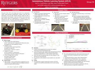
❖ Testing
➢ The proportional, integral, and derivative portions of the PID
controller were modified systematically to arrive at the working
model.
The goal of the AVLS is the design and control of an autonomous
vehicle, using networked communication, computer vision and route
optimization. Lane and traffic indicator detection enable the robot to
avoid obstacles and navigate a mock city testbed. Newly discovered
paths between nodes are communicated to a centralized server and
optimized over time. This study demonstrates important capabilities of
autonomous travel as a widespread form of transportation.
Testing and Simulation
❖ Intersections
➢ QR codes are used to uniquely identify
intersections.
➢ ZBar library is used to locate QR
codes and recognize them.
■ QR codes are used to determine
distance from the intersection.
■ QR codes are located underneath
stop signs.
Future Developments
❖ The current implementation has a half second of network lag and
close to a full second of computation time. Possible solutions
include:
➢ On-board processing on a larger vehicle; Reduced latency
➢ Graphics Processor Parallelization; Faster computation
❖ A proprietary mapping tool may be a good supplement for
simulation design, as more precise parameters like road events and
road type could increase the realism of the project.
❖ Multiple local servers can be created to communicate with cars
within a few miles of it, much like a cellular tower.
Group 34