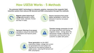
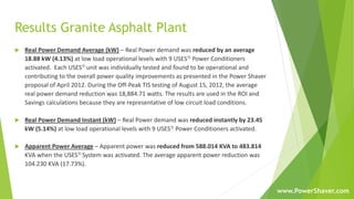
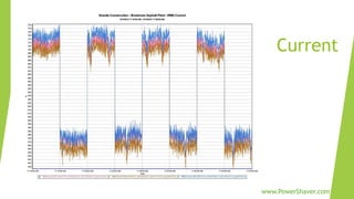
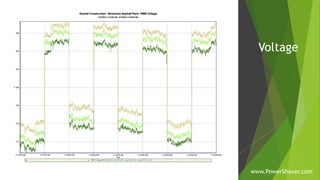
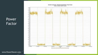
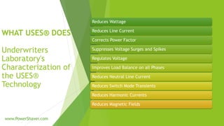
Advertisement

Power Shaver Energy Saving Systems

Dec. 15, 2020
Advertisement

More Related Content

Advertisement

Power Shaver Energy Saving Systems

  1. UNIVERSAL SHUNT EFFICIENCY SYSTEM USES® MFG INC www.PowerShaver.com
  2. www.PowerShaver.com
  3. PRODUCT INSTALLATIONS www.PowerShaver.com
  4. WHAT USES® DOES Underwriters Laboratory's Characterization of the USES® Technology Reduces Wattage Reduces Line Current Corrects Power Factor Suppresses Voltage Surges and Spikes Regulates Voltage Improves Load Balance on all Phases Reduces Neutral Line Current Reduces Switch Mode Transients Reduces Harmonic Currents Reduces Magnetic Fields www.PowerShaver.com
  5. Certifications and Approvals  Underwriters Lab [UL]: File #E132743 Category:5B81 Industrial Control Equipment  Canadian Standards Ass [CSA]: Category: LR99910 / Master Contract: 234841  Conformité Européene [CE Mark]: Directive 2006/95/EC: The Low Voltage Directive Standards: IEC 61558-1 Safety of power transformers, power supplies & similar products 2005  Patent Numbers: US: 5105327 – A.C. Power Conditioning Circuit  US: (Pending) 20120194313 - A.C. Power Conditioning Circuit  International: (Pending) WO2012102691 – AC Power Conditioning Circuit  General Services Administration [GSA]: Schedule 70: General Purpose Commercial Information Technology Equipment, Software and Services: Cooperative Purchasing and Surge Suppressor  New York City Approval: Submission #: 92A0390  Funacion Institito de Ingenieria, Caracas, Venezuela: Electric and Electric System Engineering Center Test Report No, 24-000593 www.PowerShaver.com www.PowerShaver.com
  6. Product Specifications Model XL-R XL-1 XL-3D 208 XL-3Y 208 XL- 3D 240/250 XL- 3Y 240/250 XL-3D 480 XL-3Y 480 XL-3D 600 XL-3Y 600 Line Voltage 120/240 VAC 120/240 VAC 208 VAC 120/208 VAC 240/250 VAC 120/240/250 VAC 480 VAC 277/480 VAC 600 VAC 347/600 VAC Nominal Frequency Power Dissipation per 10X1000 μsec. >1,000 >1,100 >1,400 >2,400 >1,400 >2,400 >3,000 >4,500 >3,300 >6,000 Peak Pulse Current >100,000 >100,000 >100,000 >200,000 >100,000 >200,000 100,000 200,000 100,000 200,000 Max Surge Current per 8x20 μsec. 40,000 40,000 40,000 40,000 40,000 40,000 40,000 40,000 40,000 40,000 Nominal Clamping Voltage VRMS 130V/250V 130V/250V 130V/250V 130V/250V 240/250V 120/250V 580V 320V/ 580V 680V 460V/ 680V Maximum Clamping Voltage 224V/432V 224V/432V 432V 224V/432V 553V 224V/553V 1,000V 533V/ 1,000V 1175V 795V/ 1175V Response Time Surge Rebound Standby Power >8 WATTS >10 WATTS >15 WATTS >15 WATTS >19 WATTS > 17 WATTS >20 WATTS >20 WATTS >30 WATTS >30 WATTS Total Capacitance >120 UF >200 UF > 450 UF > 450 UF > 450 UF > 450 UF >300 UF >320 UF >280 UF >280 UF Operating Temperature Unit Temperature Rise Audible Noise at 3’ Operating Life Line Connections (THHN single cond.) #10 #10 #6 #6 #6 #6 #4 #4 #2 #2 Female Tread Connection 1/2" 1/2" 3/4" 3/4" 3/4" 3/4" 1" * 1" 1-1/4" ** 1-1/4" Circuit Breaker Required 30A, 2 POLE 30A, 2 POLE 50A, 3 POLE 50A, 3 POLE 50A, 3 POLE 50A, 3 POLE 70A, 3 pole 70A, 3 pole 90A, 3 pole 90A, 3 pole Dimensions (HxWxD) 12”x 10”x 7” 12”x10”x 7” 16”x 13”x 8” 16”x 13”x 8” 16”x 13”x 8” 16”x 13”x 8” 16”x 13”x 8” 16”x 13”x 8” 16”x 13”x 8” 16”x 13”x 8” Estimated Weight 9 LBS 11 LBS 19 LBS 19 LBS 19 LBS 19 LBS 28 LBS 28 LBS 31 LBS 31 LBS Est. Shipping Weight 14 LBS 16 LBS 24 LBS 24 LBS 24 LBS 24 LBS 33 LBS 33 LBS 36 LBS 36 LBS RF Filter 3 6 9 9 9 9 9 9 9 9 ISO Transformer 1 2 3 3 3 3 3 3 3 3 Step up Transformer 1 2 3 3 3 3 3 3 3 3 KW Reduction Value .75-1.0 kW kWh/hr 1.2-1.7 kW kWh/hr 3.0-4.0 kW kWh/hr 1.7-2.5 kW kWh/hr 3.5-4.5 kW kWh/hr 3.0-4.0 kW kWh/hr 4.5-6.0 kW kWh/hr 3.5-4.5 kW kWh/hr 6.0-7.0 kW kWh/hr 4.5-6.0 kW kWh/hr Warranty * if conductor run is over 2' use adaptor to increase conduit to 1-1/4" ** if conductor run is over 2' use adaptor to increase conduit to 1-1/2" < 2°C after 24 hours under full load conditions 150,000 hours with over 95% survival 3 Years 50/60 HZ -40°C TO 70°C < 2dBA < 15 NANO SECONDS INHERENT SELF HEALING PROPERTIES www.PowerShaver.com
  7. Installation Instructions USES® SHUNT EFFICIENCY SYSTEM INSTALLATION INSTRUCTIONS BB CC A A B B C C FIGURE 1. I USES® UNIT PANEL MAIN RED BLACK -00—BLUE N E U T R A Table 1 USES® MODEL Ph.-Ph Voltage Ph.-N Voltage USES® Current XL-3D 480 480 N/A 31 MODEL: XL-3D 480 PARTS REQUIRED: Parts to be supplied by the installer. Similar parts may be substituted. Additional parts may be required depending upon installation configuration. 1. Circuit breaker: 70 amp 3 pole (SWD rated) 2. PVC pipe (size/ quantity as required) 3. PVC T/A (size/ quantity as required) 4. PVC LB (size/ quantity as required) 5. Wire: use #4 THHN single conductor 6. When not installing the 70 amp breaker into existing panels, use a disconnect rated for 100 amps or larger and still fuse for 70 amps CAUTION: DEENERGIZE ALL ELECTRICAL POWER TO THE PANEL AND EQUIPMENT BEFORE COMMENCING INSTALLATION. CAUTION: The point at which the USES® unit is connected to the electrical system must be on the line side of any controller for any motor or load. CAUTION: Confirm all phase-to-phase and all phase-to-neutral voltages match those listed in Table 1 for the model being installed before commencing installation. CAUTION: USES® unit must be installed by a licensed electrician. Installer is responsible to ensure all aspects of installation comply with the NEC and local electrical codes. All foreign country installations must comply with their electrical codes. CAUTION: USES® unit must be installed on the line side of a variable speed drives, magnetic motor controllers and frequency control drives. If put on the load side equipment damage may occur INSTALLATION: 1. Install the circuit breaker in the electrical panel. " 2. Mount the USES® unit. The total wiring length from unit to the circuit breaker must be 10' or less. 3. Run conductors and the neutral wire (if present) into the panel. 4. Connect neutral wire (if present) to neutral bar in the panel 5. Connect conductor wires to the circuit breaker. 6. When not installing a 70 amp breaker into existing panels, use disconnect rated for 100 amps or larger and still fuse for 70 amps. OPERATIONAL CHECKS: 1. When ready to energize the USES® unit, shut the circuit breaker 2. Observe the lights on the side of the USES® unit. All should be lit and equally bright. If not, deenergize the USES® unit, verify the wiring is correct ant that proper phase-to-phase and phase-to-neutral voltages exist. Contact your USES® dealer if the voltage is correct but the lights were not lit or equally bright. 3. Confirm that the current on the conductors from the USES® unit to the circuit breaker as listed in Table 1 (± 20%) for the model being installed. 4. Periodically verify the indicator lights are lit and equally bright. Contact your USES® dealer if they are not. * If the breaker space is not available in an electrical panel or if the USES® unit is being installed local to a load a circuit breaker disconnect may be used provided it meets NEC requirements. The point at which the USES® unit is connected to the electrical system must be on the line side of any controller for any motor or load. 01/11 ©1995 USES MFG INC. All rights reserved www.PowerShaver.com
  8. Magnetic phase balancing of voltage and current to safely reduce waste, demand, friction and heat in loads; Passive resonance-free power factor correction to reduce the demand of reactive non-power currents; Harmonic filtering of non-power currents to reduce the billed kWh consumption and improve power quality; Transient energy conversion through the surge protections self-healing magnetic chokes – energy above the operational voltage is absorbed, re- constituted, and returned to the customer as usable safe power; Power generation via the USES® proprietary chokes: voltage and current are generated from each phase and injected into the adjacent phases as usable power, reducing kW demand and kWh consumption. How USES® Works – 5 Methods The patented USES® technology is a dynamic, passive, resonance-free magnetic field induction system that reduces kW demand and kWh consumption through five methods: www.PowerShaver.com
  9. Results Granite Asphalt Plant  Real Power Demand Average (kW) – Real Power demand was reduced by an average 18.88 kW (4.13%) at low load operational levels with 9 USES Power Conditioners activated. Each USES unit was individually tested and found to be operational and contributing to the overall power quality improvements as presented in the Power Shaver proposal of April 2012. During the Off-Peak TIS testing of August 15, 2012, the average real power demand reduction was 18,884.71 watts. The results are used in the ROI and Savings calculations because they are representative of low circuit load conditions.  Real Power Demand Instant (kW) – Real Power demand was reduced instantly by 23.45 kW (5.14%) at low load operational levels with 9 USES Power Conditioners activated.  Apparent Power Average – Apparent power was reduced from 588.014 KVA to 483.814 KVA when the USES System was activated. The average apparent power reduction was 104.230 KVA (17.73%). www.PowerShaver.com
  10. Results Granite Asphalt Plant Continued  Apparent Power Instant – The instant Apparent Power reduction was 113.571 kVA (19.31%) at low load operational levels with 9 USES Power Conditioners activated.  Reactive Power – Under low load, the Reactive Power was reduced from 370.045 KVAR to 193.863 KVAR when the USES System was activated. The average reactive power reduction was 176.566 KVAR (47.7%).  Power Factor – Under low load, the Power Factor improved from 78% to 92% (18%) and remained lagging when the USES System was activated.  Amperage – Under low load, the circuit Amperage was reduced by 135.53 amps (19.2%) on each phase when the USES System was activated.  Voltage – Voltage improved by an average of 4.73 volts (.985%) per phase (VAB, VBC, VCA) when the USES System was activated. www.PowerShaver.com
  11. Real Power www.PowerShaver.com
  12. Apparent Power www.PowerShaver.com
  13. Reactive Power www.PowerShaver.com
  14. Current www.PowerShaver.com
  15. Voltage www.PowerShaver.com
  16. Power Factor www.PowerShaver.com
  17. Customer Reference: more available at www.PowerShaver.com  Isola, CA: Per ISOLA’s corporate energy reduction desires, the USES® XL model line was installed to reduce energy consumption and electrical costs of operation and to solve a spiking and sagging voltage condition from the utility district’s local distribution system that has been interrupting and shutting down Isola’s 24/7 manufacturing on a regular basis. Our Isola engineers have been very impressed with the Power Shaver system to accomplish our goals. Very surprising to our engineering and accounting staff tasked with evaluating the energy reduction and cost-savings ability of the USES® system, was the additional 27% reduction in electrical cost that we verified. This savings is in addition to the Power Shaver guaranteed $50,000 per year and 18-month payback. Isola’s actual payback period for our USES® system is 13 months. Isola Group has determined the USES® XL system to be a valuable asset to our company and will continue to recommend it to our industry associates. John Poma, Isola HSE Engineer Isola Group • Elk Grove, California www.PowerShaver.com
  18.  Island Colony HI: The AOAO ISLAND COLONY is a 740-room condominium/ hotel and is the tallest building in Waikiki, Honolulu, Hawaii. For many years, we have experienced very poor power quality from our utility, including frequent brownouts and outages. The result of these conditions has been damaging to our equipment — such as burned-out elevator control boards, destroyed closed circuit surveillance systems and cameras, along with a very high rate of LED driver failures. We installed the Power Shaver USES® efficiency and conditioning system to improve power quality and protect our facility from damage. I am happy to share that the USES® system has eliminated the elevator and CCTV power quality-related interruptions and damage and significantly reduced the LED driver failure rate. In addition to these benefits, the adjusted energy and cost reductions provided by the USES® system are at approximately 10%, exceeding the pre-installation projections. The USES® system is on track to pay for itself in less than one year. Ashley Auten, General Manager AOAO Island Colony • Honolulu, Hawaii Customer Reference: more available at www.PowerShaver.com www.PowerShaver.com
  19. Some Satisfied Customers www.PowerShaver.com
  20. Next Steps: What Power Shaver Needs to Proceed  All pages of last 12 months utility bills  Completed Proposal Information Worksheet www.PowerShaver.com
  21. Contact Power Shaver for an Authorized Distributor near you. Power Shaver Authorized Distributor www.PowerShaver.com
Advertisement