Welkin p1 instructions
•
0 likes•32 views

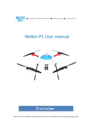
WELKIN-P1 is one cost effective quadcopter produced by WELKINUAV.

Recommended
Recommended
More Related Content
What's hot
What's hot (15)
Similar to Welkin p1 instructions
Similar to Welkin p1 instructions (20)
Recently uploaded
Recently uploaded (20)
Welkin p1 instructions
- 1. Welkin P1 User manual Incorrect use or operation of this product may result in personal injury and property damage, and Disclaimer
- 2. Shuxiying Technology (Chengdu) Co., Ltd assumes no responsibility for this. This product is not suitable for use by minors. Please use this product after reading this product manual in detail. Shuxiying Technology (Chengdu) Co. and Ltd do not bear any liability for personal injury and property damage caused by the following reasons: 1. Use this product in case of alcohol, fatigue and other poor physical conditions or poor mental state; 2. The product is not assembled or used in accordance with the correct instructions in this manual; 3. Damage caused by replacing or modifying this product by yourself; 4. The UAV itself has problems such as natural wear and tear, damage to the line, and so on; 5. The UAV is in an abnormal state and is still forced to fly, resulting in losses; 6. Loss caused by the flight of the aircraft in a magnetic field interference zone, radio interference zone, no-fly zone, or open field; 7. Flying in inclement weather; 8. Due to improper use of users caused by illegal or three party personnel, property losses, Shuxiying Technology (Chengdu) Co., Ltd is not liable jointly and severally. 1. System Overview Product introduction Welkin P1 is an industrial grade drone independently developed by our company. The airframe is Statement Please read carefully the ICAO and local airspace regulations and drone management regulations and related regulations. Users who do not comply with the above regulations may violate national laws and regulations. Here, the user is committed to his or her own actions and all direct or indirect liability for failure to use the flight restrictions feature in this manual.
- 3. made of carbon fiber material, and the frame, upper cover, arm, landing gear and electric frame are all designed with light structure. It is lighter and more beautiful while ensuring rigidity and strength. The arm is designed with umbrella folding, which makes assembly and transportation quicker and more convenient. This product is equipped with a multi-rotor flight control system independently developed by our company. The advanced algorithm ensures the stability and safety of the flight platform. Functional characteristics Extra large payload, long endurance and flight distance Quick release structure for easy carrying and transportation Rainproof design, meet GJB150.8 (on the standard of rain test) Carbon fiber integrated molding body, good rigidity and light weight Wind resistance up to 5 levels (pass the sea test) Precise attitude control HD video, image output (in the case of barrier free, the distance can reach 30KM) 2. Product List List In order to facilitate transportation, Welkin P1 adopts a folding design, which has been tested for quality and flight test before leaving the factory to ensure stable and reliable products. Before you start using it, check the contents of the package. The following is a list of Welkin P1 items. Table 1 Packing List
- 4. No. Name Reference Picture Quantity 1 Drone Body 1 2 Charger 1 3 Power Battery 2 4 Remote Control 1 5 GCS (Software) / 1 6 Task Equipment Depends on what equipment client buy Depends on how many equipment client buy 7 Flight Case 1 8 Graph Transmission Equipment Different equipment, different styles 1
- 5. Index Parameter Table 2 Welkin P1 Parameters Maximum Flight Course 40km Cruise Speed 0~15m/s Duration Time 45 min Flight Height 1~4000m Remote Control Distance Maximum 40km (obstacle-free) Control Mode Automatic / Manual Image Transmission Mode Real Time Transmission Image Transmission Format 1920*1080 HD (H.264);720*576 SD (MPEG-2) Image Transmission Distance Maximum 30km (obstacle-free) Image Encryption Device AES Encryption Produce Size 1200*1200*500mm Takeoff Weight 8~12kg Waterproof Grade Meet the standard of GJB 150.8 on rain test Anti-wind Capability ≤5 Scale (Pass the sea test) Table 3 Remote Control Parameters Remote control name: Futaba T14SG Helicopter/fixed wing/multi-rotor compatible equipment 2.4GHz working frequency Transmitter: 14SG 14 channel remote control *1 Receiver: Futaba R7008SB 2.4G high voltage plate receiver *1 Emitter: 6V, 1800amh (HT5F1800B) Charger: HBC-3C special charger *1 Hanging band *1 Support SD card upgrade (Cards need to be purchased separately)
- 6. Table 4 Charger Parameters Input voltage AC 100~240V Output power 1080W (540W*2) Charging current 1~20A*2 (adjustable) Maximum balance current 1.2A Battery type lithium battery, high voltage lithium battery Number of lithium battery sections 6 knots * 2 (6S) Charging mode fast charging, balanced charging mode, storage and maintenance Size 272x202x118.6mm Weight 4.88KG 3. Component Fuselage Parameters Precautions for packaging and transportation 1. Please take care when the aircraft is taken out of the box, remove it, unfold it, fold it and recycle it. 2. Do not squeeze during transportation, do not violently impact, so as not to fall and damage the body. 3. Coverage during transportation should be carried out to avoid rain, exposure and mixed transportation with corrosive materials. 4. It should be stored in a warehouse with ventilation, moisture, rain and sun protection, and should not be stored together with corrosive materials.
- 7. 4. System Operation Description Operation Process Environmental Confirmation 1.Pay attention to the choice of the flight site. Please do not fly in areas with large human flow, many floors, high voltage power lines, and airport restrictions. Please look for empty space without high-rise building shelter to fly. 2. Pay attention to the choice of landing site, pay attention to the height of the highest building to determine the return altitude; 3. Do not fly in harsh environments, such as strong winds or rainy days; 4. It is forbidden to fly in areas with strong magnetic field interference, such as steel bridges and base stations; 5. Do not operate with propellers indoors; 6. Check if the route meets the above requirements; 7. Check if the GPS is normal and check if the GPS tracker is carried. System Check (before power on) 1. Check if the aircraft outer cover, arms, landing gear, joint of arms and fuselage have cracks or damage; 2. Check if the GPS module is installed in the correct direction;
- 8. 3. Make sure that the screw at the joint is tightened; 4. Check if the direction of the blade is correct and there is no damage (blade surface crack or edge cracking); 5. Check if the blade fixing tightness is appropriate; 6. Check if the motor is firm (whether the outer rotor and the inner stator fit together); 7. Check if the guide is fixed firmly; 8. Check the landing gear for looseness and damage; 9. Check if the battery compartment is in place and fixed firmly; 10. Check if the power of battery is sufficient; 11. Check if the mission equipment is fixed firmly; 12. Check if the power supply line and transmission line of the task equipment are connected. 13. Check the center of gravity of the aircraft in the case of battery and task equipment installed. 14. Check the battery power of remote control; 15. Check if the remote control channel is reset. 16. Please be sure to turn on the remote control before powering up the aircraft. System Check (after power on) 1. Check the tightness of the power plug; 2. Check if the led light flashes normally; 3. Check if the settings of out-of-control protection and low voltage protection are normal; 4. Check if the retract of landing gear is normal (An aircraft with a retractable functional landing gear); 5. Calibrate geomagnetism (When it in a new flight environment); 6. Check if the task device control is normal; 7. Check if the power supply status and data, image transmission function is normal, ensure the connection between the aircraft and the ground station is successful, and ensure that the signal strength is good; 8. Check if the remote control signal is normal. The remote control calibration needs to confirm that if the remote control channels are normal through the calibration page. In the case of more than one remote controller in the field, make sure that the receiver only corresponds to one remote controller. Ground Station and Autonomous Route Confirmation 1. Check if the GPS signal is normal, please ensure that the number of satellites more than 10; 2. Check if the flight control self-test items are all normal; 3. Voltage calibration needs to measure the actual battery voltage. If the voltage difference with the software feedback is greater than 0.1V, please be sure to select the correct battery type and number of cells;
- 9. 4. Check if the corresponding posture of the aircraft is correct; 5. Confirm the height of all way points, they all needs to be higher than the actual environmental altitude (if necessary, you can use a small aircraft to test the flight route); 6. Make sure that there are no obstacles on all route lines. Check Items In Flight 1. The aircraft needs to switch to GPS mode when it is about 10m high from the ground, and hover above 5 seconds at fixed point to check if the hover is normal; 2. Check if the magnetic compass is normal; 3. Check if the remote control is normal under the attitude mode and GSP mode; 4. Please pay attention to the battery voltage. When the voltage is insufficient, please return and land in time; 5. Keep the remote control open all the time, and switch flight mode to GPS mode. Push the throttle to 50%, and keep it during the whole flight until landing then push the throttle down to 0%. Landing Check 1. The landing gear must be deployed before landing. 1. Check if the environment of return point and the landing pad are safe; 2. Check the situation of aircraft voltage. Check After Landing (one by one) Do not approach the aircraft until the propeller has stopped. 1. Ensure that the aircraft has been locked; 2. Save the data first, then power off the aircraft, and then close the remote control, map transmission, ground station and other storage components; 3. Folding machine arms, folding paddles, paddle supports and etc to put into the case. (Note that the high temperature battery should be placed at room temperature and then boxed); 4. Pay attention to the storage voltage of the battery (22.2V); 5. The package is dust-proof and moisture-proof.
- 10. Compass calibration The compass is easily interfered by other electronic devices, resulting in abnormal flight data to cause the normal flight , and even flight accidents, we need often calibrate the compass to keep the compass in optimal working condition (recommended to calibrate the compass before the first flight) Compass calibration steps 1: Turn on the remote control and turn on the power of the flight control system. 2: Switch the switch of control flight mode back and forth between any two flight modes more than 6 times quickly until the LED indicator blue light is on and enters into the calibration mode. 3: (Picture 1) Aircraft rotate (about 360°) through the direction of level and gravity as axis until the green light is on; 4: (Picture 2) The aircraft is erected with the nose facing down, and the direction of gravity is the axis rotation (about 360°) until the green light is on, so the calibration is completed; 5: After the calibration is successful. After the white LED flashes 4 seconds. The calibration mode automatically exits. If the calibration fails, the red light flashes 4 seconds. Please re-calibrate the compass from step 2. (The calibration steps are as shown below) during transportation should be carried out to avoid rain, exposure and mixed transportation with corrosive materials.
- 11. [Note] ① Please do not calibrate in areas containing ferromagnetic materials, such as magnetic mines, parking lots, building areas with underground steel bars and etc. ② Please do not carry ferromagnetic materials with you when calibrating. Such as keys and mobile phones, ③ Compass modules cannot be used normally in the Arctic Circle. ④ Compass calibration is very important, otherwise the system will not work normally. 5. How to Recharge Product Features
- 12. LiPo BATT (drone battery) charging 1. Please take out the battery and connect it to the charger. Insert the charger into the power supply, connect the battery, and display the interface after opening the switch. 2. Adjust the STATUS to adjust to LiPo BATT (lithium battery). 3. Press ENTER to confirm. 4. Press ENTER to jump to the current adjustment state and press STATUS to adjust to 8.0A. 5. Press ENTER to enter into the voltage adjustment state, press STATUS button to adjust to 22.2V (6S), press ENTER to confirm. Adjustment interface diagram
- 13. 6. Long press ENTER to enter into the [CONFIRM] interface. Other state diagram CANCEL(STOP) interface diagram 7. Cancel the selection without pressing any keys, restore to [current and voltage adjustment interface]. 8. Press ENTER to enter into the charging state, the current, voltage, charging duration and current charging capacity will be showed. Charging status interface diagram
- 14. 9. You also can press the STATUS to view other states such as battery voltage. Battery voltage state diagram 10. Press BATT/PROG to stop charging. NIMH BATT (ground station battery) charging 1. After the charger is plugged into the power supply and connected the battery, the interface will be showed. 2. Adjust the STATUS to adjust to NIMH BATT (NiMH battery). Select interface diagram 3. Press ENTER to confirm. 4. Press ENTER to jump to the current adjustment state. Press the STATUS to adjust to 4.0A, press ENTER to confirm. Current adjustment interface diagram
- 15. 5. Press and hold the ENTER key to enter into the charging state, the current, voltage, charging duration and current charging capacity will be showed. Charging state diagram 6. Press the STATUS to adjust to view other statuses. Other state diagram 7. Press BATT/PROG to stop charging. Battery use precautions 1. Pay attention to the positive and negative poles when connecting the power cord. 2. Someone should check battery while charging. It may stop charging due to temperature, time, capacity, etc. At this time, someone needs to continue to operate to make it continue charging. 3. The battery is flammable and explosive. Do not drop the battery and keep away from the fire during transportation and use. 4. This product is a rechargeable lithium polymer battery. Please connect the battery and charger correctly when charging, and avoid overcharging to damage the battery and even causing danger. 5. If battery is out of use for a long time, please keep the battery voltage at 23V. 6. If the battery expands or the surface is damaged, please contact the factory for replacement. 7. Please store in a dry, ventilated place.
- 16. 6. Remote Control Name of each part
- 17. Details
- 18. 7. Maintenance Routine Maintenance 1. Equipment, materials, and tools should be checked as per list after the end of each flight. 2. Move the photos and videos in the SD card into the computer in time to avoid the inconvenience caused by the backlog of occupying too much memory. 3. Check the integrity of the aircraft in time after the end of each flight, such as the integrity of the propellers and the guard frames. If the defect is found, it should be replaced and repaired in time. If it cannot be repaired, the aircraft should be suspended to avoid further damage. The aircraft should be repaired without any problems before continuing to fly. Daily Maintenance 1. Does the battery volume change significantly? 2. Check if the foreign matter inside the motor, clean the bearing and pay attention to oiling. 3. Check if the cleaning line of flight control surface is aging, and check components are soldered, hot melt, etc. 4. Check if the wire is deformed, such as a serpentine shape after being cooled by heat. 5. Check if the wire interface has foreign matter, oxidation, etc. 6. Check if the frame is deformed and the nut is scratched. 7. Check if the whole line is wrapped, the wires and the interface are fixed, etc., they are must be firmed, if there is loose break, replace it in time. 8. Check if the markings on the aircraft are secure. 9. For dust sensitive parts such as motors and flight controls, clean the dust in time to make sure it is clean. How long to save, how to save 1. The flight control should be sealed in a closed bag, and the plug should be kept dry. 2. Before the motor is sealed, the inside of the motor should be decontaminated, oiled, otherwise the font on the outer casing, especially the knife lettering, is easy to oxidize and rust. 3. ESC storage 4. The propellers are wrapped in plastic paper, cloth or foam sheets. It should be stored in area which is not easy to squeeze and sunless. 5. The frame need to be hung up and stored as a material.
- 19. Vulnerable parts 1. The propeller is easy to break and fragile. Please be cautious during transportation and use. Check if there is slip on the surface of the screw of the propeller and motor before flying. Please note that when replacing the propeller, etc., you need to apply the screw glue on the screw. 2. The parts on the aircraft landing gear are also vulnerable parts. Before the flight, you need to check if the landing gear is damaged and if it can be properly retracted. If there is any abnormality, do not fly, and repair it or contact the manufacturer. 3. After the aircraft completes the mission and landing, if the motor's ESC is hot, please wait it to be cool before flying again. If there is any abnormality in fever, please contact the manufacturer immediately. Contact us via: info@welkinuav.com or +8613057992905 Fellow us on : Facebook: welkinuav group or YouTube: Leone Tang Copyright@2018 WELKINUAV GROUP. WELKINUAV are trademark of Shuxiying Technology (Chengdu) Co., Ltd