Mitsubishi low voltage catalog-contactor-mitsubishi-160422014628
•
0 likes•74 views

Mitsubishi , Catalog Thiết Bị Điện Mitsubishi , Catalog Thiết Bị Điện Catalog Phụ Kiện Mitsubishi , Catalog Phụ Kiện, Catalog Mitsubishi , Catalog, https://www.dienhathe.com, Chi tiết các sản phẩm khác của Mitsubishi tại https://dienhathe.com Xem thêm các Catalog khác của Mitsubishi tại https://dienhathe.info Để nhận báo giá sản phẩm Mitsubishi vui lòng gọi: 0907.764.966

Recommended
Recommended
More Related Content
What's hot
What's hot (16)
Similar to Mitsubishi low voltage catalog-contactor-mitsubishi-160422014628
Similar to Mitsubishi low voltage catalog-contactor-mitsubishi-160422014628 (20)
More from Dien Ha The
More from Dien Ha The (20)
Recently uploaded
Recently uploaded (20)
Mitsubishi low voltage catalog-contactor-mitsubishi-160422014628
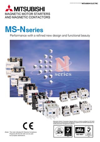
- 1. Performance with a refined new design and functional beauty ADVANCED AND EVER ADVANCING MAGNETIC MOTOR STARTERS AND MAGNETIC CONTACTORS (Note) This mark indicates EC Directive Compliance. Products with the CE mark can be used for European destinations. series Mitsubishi Electric Corporation Nagoya Works is a factory certified for ISO14001 (standards for environmental management systems) and ISO9001(standards for quality assurance managememt systems)
- 3. Substantial safety and functionality realized with a full lineup Incorporation of CAN terminal for simple wiring Simple inspections The contactor can be inspected easily by removing the arc cover. Built-in surge absorber The model with built-in surge absorber for coils is obtainable as an option. Pull up the screw holder. Insert the closed eyelet connector, and push up the screw holder. Tighten the screw. Stronger barrier strength is improved with the thermoplastic mold. Improved magnet By using a spiral kick-out spring, the dynamic balance of the moving parts is improved, bouncing is reduced, and the core life is extended. Furthermore, the core movement is generally stabilized. The efficient magnet has been achieved through modern technology of the magnet section using a computer. The contactor has a performance to withstand a voltage drop to 35% with the closed contact. Spiral kick-out spring Coil Moving core Stationary core Small-Sized Models S-N10~N35 15mm 15mm 15mm 15mm 15mm 38.5mm Indication of absorber Surge absorber Unified design for N series The design has been unified for the MS-N series. The front face of the product is a bright white color, making the inside of the panel brighter and providing a clean image. Arc space reduced to approx. one-third! By adopting the new extinguishing mechanism, the arc space has been reduced to approx. 1/3 (Mitsubishi comparison). Compatible with International Standards Most of Mitsubishi's standard products comply with International Standards. Applicable standards: JIS, JEM, IEC, EN, VDE, BS Approved standards: UL, CSA, LR, BV, NK, KR, TÜV By adopting a CAN terminal, there is no need to remove the screws, and losing of the terminal screw is prevented by the integrated screw holder and terminal screw. The terminal screw is set in a plastic screw holder. When each pole is moved and the screw loosened, the screw is naturally set in the screw holder. This is Mitsubishi's original CAN terminal. (Patented) (S-N10CX~N35CX, SD-N11CX~N35CX, SR/SRD-N4CX) Simple installation and wiring The MS-N series contactors, starters and relays can be installed on a mounting rail (35mm width). The terminals of these coils are arranged on the contactor with simple wiring. Furthermore, the distance between the center of the rail and the coil terminals is unified at 38.5mm. (S-N10 to N21, MSO-N10 to N21 and SR-N4) CAN terminal realizes safety and speedy The models with finger protection are safer and speedier even if the lug of a closed type eyelet (ring) terminal plate is used. (S-N10CX~N35CX, SD-N11CX~N35CX, SR/SRD-N4CX)
- 4. Medium-and Large-Sized Models: S-N50~S-N800 DC Electromagnet with AC Operation (Patented) Even Greater Contact Reliability MATCH WITH ELECTRONIC CONTROL FOR FACTORY AUTOMATION If the magnetic relay coil is opened and closed near an electronic circuit, malfunctioning of the electronic circuit could be induced by a surge voltage. The UN-SA type surge absorber suppresses the surge voltage when this coil is opened and closed. In addition to the general varistor type and the CR type that lays importance on suppressing the induction voltage when starting, the type with operating indicator (varistor type), and the varistor type with CR are available. One-touch surge absorber An easy-to-install terminal cover, which lays importance on further safety and is compatible with finger protection, has been prepared. Finger Protection Compatible A new extinguishing structure, which eliminates the blow off of hot gas (arc) to the front (direction to door of control panel) when the current is cutoff has been incorporated. In addition to improved safety, the freedom of panel design has been increased allowing space to be saved. The arc blowoff direction has been changed to further improve safety and space conservation This is an auxiliary contact unit with low level contact, capable of opening and closing the low voltage and minute current of the electronic control circuit. It can be installed with one touch onto the magnetic contactor or magnetic relay that opens and closes the power of the motor, etc. The junction relay for opening and closing the low voltage and minute current is not needed, so this unit is suitable for opening and closing electronic input circuits in programmable logic controllers, etc. A compact microswitch is used for the low level contact, so the unit will not malfunction due to fields and surge voltages from the main circuit current and coil of the magnetic contactor. A 1NO+1NC low level contacts and 1NO+1NC standard contacts are built-in, so the opening and closing of 200VAC and 24VDC can be handled with one unit. Auxiliary contact unit with low level contact S2 types of inputs The long life no-contact output type (UN-SY21, SY31) and contact output type (UN-SY22, SY32) are available. SOne touch installation The UN-SY21, SY22, SY31 and SY32 types can be mounted with one touch onto the coil terminal. Post-installation work is easy. SSingle standalone unit A single unit installation type (UN-SY11, SY12) is available for the S-KR11 and S-N80 to N400 magnetic contactor. Interface unit Coil power consumption is greatly low so MS-N Series contactors can be controlled by almost any type of relay, even small output relays of programmable controllers. Lower Power Consumption When switching a coil, the energy will be desipated within internal circuit of electromagnet Contact reliability has been greatly improved by the bifurcated auxiliary moving contact Less Noise nor Surge from Coil The number of coil types has been cut by two-thirds and there is no need to re-wire for different frequencies. The coil also withstands large voltage drops. Contactor Coils Have Ultra-Wide Range of Ratings DC excitation does not cause humming so operation is quiet. Internal circuit of the electromagnet Humming Completely Eliminated S-N 5 10 10 10 10 Frame N50/N65 N80/N95 N125~N220 N300/N400 N600/N800 S-K 10 10 30 50 10 Arc space(mm) Direct installation is possible on the following units: S-N series (Magnetic contactor) 65A frame or less SR-N series (Magnetic relay) 4-pole, 5-pole and 8-poles types C Coil R Contact spring Bifurcated moving contact Bifurcated moving contact Stationary contact Arc space
- 5. TYPE REFERENCE LIST ........................................................................................................................................ 1 1. GENERAL PURPOSE CONTACTORS & STARTERS ........................................ Series MS-N 1.1 Conformity to International Standards ....................................................................................................... 2 1.1.1 List of Marked Type .............................................................................................................................3 1.1.2 TÜV Certified Type ...................................................................................................................................3 1.1.3 UL Approval for U.S.A. and Canada ......................................................................................................... 4 1.1.4 Approved Marine Standards ..................................................................................................................... 5 1.2 Selection Guide ............................................................................................................................................. 6 1.3 The Overview (Type designation breakdown)............................................................................................ 8 1.3.1 Non-Reversing Types ...............................................................................................................................8 1.3.2 Reversing Type.........................................................................................................................................9 1.4 Technical Data of Series S-N Contactors ................................................................................................. 10 1.4.1 Ratings and Characteristics .................................................................................................................... 10 1.4.2 Performance of Series S-N Contactors .................................................................................................. 12 1.4.3 Mounting Attitude of Starters and Contactors ......................................................................................... 12 1.5 When Ordering ............................................................................................................................................ 13 1.6 Selection Table of Contactors ................................................................................................................... 14 1.6.1 Non-Reversing Contactors ............................................. Type S-N , SD-N ......................................... 14 1.6.2 Reversing Contactors ..................................................... Type S-2xN , SD-2xNN .............................. 15 1.6.3 Non-Reversing Mechanically Latched Contactors .......... Type SL-N , SLD-NN .................................. 16 1.6.4 Reversing Mechanically Latched Contactors.................. Type SL-2xN , SLD-2xN , SLxS-NN ............. 17 1.7 Selection Table of Direct-On-Line Motor Starters.................................................................................... 18 1.7.1 Non-Reversing Motor Starters without Enclosure(IP 00) Type MSO-N ................................................. 18 1.7.2 Reversing Motor Starters without Enclosure(IP 00)........ Type MSO-2xN ............................................. 19 1.7.3 Enclosed Non-Reversing Motor Starters(IP 20) ............. Type MS-N .................................................... 20 1.7.4 Enclosed Non-Reversing Motor Starters with Pushbutton Switch(IP 20) ............. Type MS-N PM ................. 21 1.8 Optional Parts and Accessories for Contactors ...................................................................................... 22 1.8.1 Replacement Coils.................................................................................................................................. 22 1.8.2 Replacement Contact Kits ......................................................................................................................22 1.8.3 Auxiliary Contact Blocks ......................................................................................................................... 23 1.8.4 Mechanical Interlocks .............................................................................................................................23 1.8.5 Connecting Bar Kits ................................................................................................................................ 23 1.8.6 Surge Absorbers ..................................................................................................................................... 24 1.8.7 Terminal Covers ..................................................................................................................................... 24 1.8.8 Pneumatic Time Delay Modules ............................................................................................................. 24 1.8.9 DC Interface Modules .............................................................................................................................24 1.9 Connections and Contact Arrangement ................................................................................................... 25 1.9.1 S, SD-N................................................................................................................................................... 25 1.9.2 S, SD-2xN ...............................................................................................................................................26 1.9.3 SL, SLD-(2x)N ........................................................................................................................................ 27 1.9.4 MSO-(2x)N.............................................................................................................................................. 28 1.9.5 MS-N....................................................................................................................................................... 29 1.9.6 MS-N PM .............................................................................................................................................. 29 1.10 Outline Dimensions .................................................................................................................................. 30 1.10.1 Outline Dimensions of Non-Reversing Contactors ............................................................................... 30 1.10.2 Outline Dimensions of Reversing Contactors ....................................................................................... 31 1.10.3 Outline Dimensions of Open Type Starters .......................................................................................... 32 1.10.4 Outline Dimensions of Enclosed Motor Starters ................................................................................... 33 CONTENTS
- 6. 2. MOTOR PROTECTION RELAYS 2.1 Thermal Overload Relays ............................................................................. Series TH-N ........................ 34 2.1.1 Selection Guide of Thermal Overload Relays......................................................................................... 35 2.1.2 Selection Guide of the Current Transformers for TH-N600KP ............................................................... 36 2.1.3 Technical Data ........................................................................................................................................ 36 2.1.4 Selection Guide of Quick Trip Thermal Overload Relay ......................................................................... 36 2.1.5 Operating Characteristics of Thermal Overload Relays ......................................................................... 37 (Connecting wire size : Refer Table 2.1.2) 2.1.6 Optional Parts and Accessories.............................................................................................................. 38 2.1.7 Outline Dimensions................................................................................................................................. 39 2.2 Electronic Motor Protection Relays ............................................................ Series ET-N ........................ 40 3. DEFINITE PURPOSE CONTACTORS & STARTERS 3.1 DC Contactors ............................................................................................... Series DU-K/A .................... 43 3.2 Medium Voltage Vacuum Contactors ......................................................... Series SH-V ........................ 46 3.3 Compact 3-Pole Contactors......................................................................... Series S-N 8 .................... 49 3.4 NC Main Contact Contactors ....................................................................... Series B-N/A ...................... 50 3.5 Heavy-Duty Clapper-Type Contactors ........................................................ Series CD ........................... 52 3.6 Delay Open Type Magnetic Starters & Contactors .................................... Series S/MSO-N DL ........ 54 3.7 DC Interface Contactors ............................................................................... Series SD-M ....................... 56 3.8 DC Interface Modules ................................................................................... Series UN-SY ..................... 57 4. RELAYS 4.1 Contactor Relays .......................................................................................... Series SR-N ........................ 59 4.1.1 Specifications..........................................................................................................................................60 4.1.2 Auxiliary Contact Blocks ......................................................................................................................... 61 4.1.3 Contact Arrangements of Contactor Relay ............................................................................................. 62 4.1.4 Spare Coils & Accessories ..................................................................................................................... 62 4.1.5 Outline Dimensions................................................................................................................................. 62 4.2 Voltage Detection Relays ............................................................................. Series SRE ......................... 63 4.3 Re-Starting Relays ........................................................................................ Series UA-DL ..................... 65 4.4 Solid State Time Delay Relays..................................................................... Series SRS-H ..................... 67 4.5 Pneumatic Time Delay Relays ..................................................................... Series SRT-N ..................... 68 5. STAR-DELTA STARTERS ................................................................................... Series EYD-N 5.1 Selection Table............................................................................................................................................70 5.2 Specifications.............................................................................................................................................. 71 5.3 Outline Dimensions ....................................................................................................................................72 5.3.1 Open Type (EYDO-N).............................................................................................................................72 5.3.2 Enclosed Type (EYD-N) ......................................................................................................................... 72 6. SOLID STATE CONTACTORS ............................................................................ Series US-K 6.1 Features .......................................................................................................................................................73 6.2 Product Scope............................................................................................................................................. 74
- 7. 1 TYPE REFERENCE LIST DescriptionType NC main contact contactors ............................................................................................50 Heavy-duty clapper-type contactors ................................................................................52 DC contactors..................................................................................................................43 Electronic motor protection relays ...................................................................................40 Star-delta starters ............................................................................................................70 General purpose enclosed type motor starters ...............................................................20 Enclosed non-reversing motor starters with pushbutton .................................................21 General purpose open type motor starters......................................................................8,18,32 Delay open type magnetic contactors .............................................................................54 General purpose open and reversing type motor starters ...............................................9,19,32 Plug-in sockets for,UA-DL2 .............................................................................................66 Compact 3-pole contactors .............................................................................................49 General purpose contactors ............................................................................................2~ DC interface contactors ...................................................................................................56 Delay open type magnetic contactors .............................................................................54 General purpose reversing contactors ............................................................................26 Medium voltage vacuum contactors ................................................................................46 Medium voltage reversing vacuum contactors ................................................................46 Mechanically latched contactors .....................................................................................16 Mechanically latched reversing contactors......................................................................17 Mechanically latched and normal reversing contactors...................................................17 Contactor relays ..............................................................................................................59 Voltage detection relays ..................................................................................................63 Solid state time delay relays............................................................................................67 Pneumatic time delay relays ...........................................................................................68 Thermal overload relays ..................................................................................................34 Saturable reactors for TH-N ............................................................................................38 Auxiliary contact blocks for SH-V ....................................................................................48 Re-starting relay ..............................................................................................................65 Surge absorbers for SH-V ...............................................................................................47 Auxiliary contact blocks ...................................................................................................23,44,61 Mechanical interlocks for S-N..........................................................................................23 Reset release for TH-N ...................................................................................................38 Surge absorbers for S-N and SR-N4...............................................................................24 DC interface modules for S-N .........................................................................................24,57 Trip indicator for TH-N .....................................................................................................38 Pneumatic time delay modules .......................................................................................24,72 Solid State Contactors.....................................................................................................73 Ref.Page B(D)-A / N CD- DU(D)- ET-N EYD(O)-N MS-N MS-N PM MSO(D)-N MSO-N DL MSO(D)-2XN PF- S-N 8 S(D)-N SD-M S-N DL S(D)-2XN SH(L)(D)-V SH(L)(D)-2XV SL(D)-N SL(D)-2XN SLXS-N SR(D)-N SRE- SRS-H SRT(D)-N TH-N THR- UA-AXVV UA-DL2 UA-SU UN-AX UN-ML UN-RR UN-SA UN-SY UN-TL UN-TR US-K
- 8. 2 1. GENERAL PURPOSE CONTACTORS & STARTERS Mitsubishi magnetic motor starters and contactors are designed to conform to the relevant IEC recommendations and to the standards of as many countries as possible. Specifically, they conform to the following: VDE0660 NEMA-ICS IEC60947-4-1 EN60947-4-1 1.1 Conformity to International Standards Series MS-N International Europe Germany U.S.A Notes:1. : CE Mark (Manufacturer’s Declaration) == Standard model applicable, marking on the product. UL, TÜV == Standard model applicable, marking on the product. NK == Standard model applicable, Certificate No. on the product. q : Standard model applicable, no marking on the product. If marking required, order model name followed by suffix “DZ”. ᭺ : Standard model applicable, no marking on the product. ✩ : Special model applicable, marking on the product. Order model name followed by suffix “UL”. — : Not applicable to the Standard or not approved. 2. Finger protection type is certified according to DIN VDE 0106 part 100. For finger protection type, order model name followed by suffix “CX”. 3. For each certificate conditions, see next three pages. S-N10(CX) S-N11(CX)/N12(CX) S-N18(CX) S-N20(CX)/N21(CX) S-N25(CX) S-N35(CX) S-N28(CX) S-N38(CX) S-N48(CX) S-N50 S-N65 S-N80 S-N95 S-N125 S-N150 S-N180 S-N220 S-N300 S-N400 S-N600 S-N800 TH-N12(CX)KP TH-N18(CX)KP TH-N20(TA)(CX)KP TH-N60(TA)KP TH-N120(TA)KP TH-N220RHKP/HZKP TH-N400RHKP/HZKP SD-N11(CX)/N12(CX) SD-N21(CX) SD-N35(CX) SD-N50 SD-N65 SD-N80 SD-N95 SD-N125 SD-N150 SD-N220 SD-N300 SD-N400 SD-N600 SD-N800 DC Operated Contactor Overload Relay AC Operated Contactor Type Model Name (✽2) Canada U.K. France Korea Japan Lloyd’s Register of Shipping Korean Register of Shipping Bureau Veritas Nippon Kaiji Kyokai Table 1.1 AC Operated Contactor Relay SR-N4(CX) DC Operated Contactor Relay SRD-N4(CX) Auxiliary Contact Block UN-AX2(CX) UN-AX4(CX) UN-AX11(CX) UN-AX80 UN-AX150 U.S.ACanadaU.S.A Listing Recognition Europe North America / UL TÜVCE Mark ᭺ — — — — — q (✽2) ᭺ (✽2) q (✽2) ᭺ — ᭺ —— ᭺ ᭺ ᭺ ᭺ ᭺ ᭺ ✩ — — ᭺ ᭺ ᭺ ᭺ ᭺ ᭺ ᭺ ᭺ — — — — — — — — — — ᭺ — — ᭺ Marine ( Mark) ( Mark) ( Mark) ( Mark) ( Mark) ( Mark) — ᭺ (✽2) ✩ ( Mark) ( Mark) ( Mark) (✽2)
- 9. 3 1.1.1 List of Marked Type Standard Contactors Non-reversing A.C. operated D.C. operated A.C. operated D.C. operated Additional Auxiliary Contact Blocks Notes:1. Listed types are representatives and containes standard models. 2. Applicable product standards Contactors : EN60947-1, EN60947-4-1, EN60947-5-1 Thermal overload relays : EN60947-1, EN60947-4-1, EN60947-5-1 Aux. contact blocks : EN60947-1, EN60947-5-1 Mechanical interlocks : EN60947-1, EN60947-4-1, EN60947-5-1 Standard Contactors Reversing Mechanical Interlocks3 S-N10, S-N11, S-N12, S-N18, S-N20, S-N21, S-N25, S-N28, S-N35, S-N38, S-N48, S-N50, S-N65, S-N80, S-N95, S-N125, S-N150, S-N180, S-N220, S-N300, S-N400, S-N600, S-N800 SD-N11, SD-N12, SD-N21, SD-N35, SD-N50, SD-N65, SD-N80, SD-N95, SD-N125, SD-N150, SD-N220, SD-N300, SD-N400, SD-N600, SD-N800 S-2XN10, S-2XN11, S-2XN20, S-2XN21, S-2XN25, S-2XN35, S-2XN50, S-2XN65, S-2XN80, S-2XN95, S-2XN125, S-2XN150, S-2XN180, S-2XN220, S-2XN300, S-2XN400, S-2XN600, S-2XN800 SD-2XN11, SD-2XN21, SD-2XN35, SD-2XN50, SD-2XN65, SD-2XN80, SD-2XN95, SD-2XN125, SD-2XN150, SD-2XN220, SD-2XN300, SD-2XN400, SD-2XN600, SD-2XN800 UN-AX2, UN-AX4, UN-AX11, UN-AX80, UN-AX150 UN-ML11, UN-ML21, UN-ML80, UN-ML150, UN-ML220 Thermal Overload Relays TH-N12KP, TH-N18KP, TH-N20KP, TH-N20TAKP, TH-N60KP, TH-N60TAKP, TH-N120KP, TH-N120TAKP, TH-N220RHKP, TH-N220HZKP, TH-N400RHKP, TH-N400HZKP, TH-N600KP Contactor Relays A.C. operated D.C. operated D.C. Interface Contactors Non-reversing Reversing SR-N4 SRD-N4 SD-M11, SD-M12, SD-M19 SD-MR12, SD-MR19 Table 1.1.1 1.1.2 TÜV Certified Type s Contactor Notes:1. Standard models are applicable under following conditions. Main circuits : AC-3 rated current at 440V AC max. (Main contacts) and rated continuous current. Auxiliary contacts : AC-15 rated current at 550V AC max. and rated continuous current. Operation coil : AC coil designation N10~N12, N18~N48 and SR-N4 ; AC12V~AC440V N20~N35 ; AC12V~AC380V N50~N150 ; AC24V~AC500V N180~N400 ; AC48V~AC500V DC coil designation DC12V~DC220V 2. For contactors, standard models are with TÜV mark on the product. For other products, standard models are with no TÜV mark on the product. For contactor relays, order model name followed by suffix “DZ” if TÜV mark on the product is required. 3. Finger protection type is certified according to DIN VDE 0106 part 100. For finger protection type, order model name followed by suffix “CX”. 4. Models with built-in surge absorber (model name followed by “SA”) are also certified. S-N10(CX)(SA) S-N11(CX)(SA) S-N12(CX)(SA) S-N20(CX)(SA) S-N21(CX)(SA) S-N25(CX)(SA) S-N35(CX)(SA) S-N18(CX)(SA) S-N28(CX)(SA) S-N38(CX)(SA) S-N48(CX)(SA) S-N50/S-N65 S-N80/S-N95 S-N125 S-N150 S-N180/S-N220 S-N300/S-N400 SD-N11(CX)(SA) SD-N12(CX)(SA) SD-N21(CX)(SA) SD-N35(CX)(SA) SD-N50/SD-N65 SD-N80/SD-N95 SD-N125 SD-N150 SD-N220 SD-N300/SD-N400 Model Name Certificate No. EN60947-4-1 EN60947-4-1 EN60947-4-1 EN60947-4-1 EN60947-4-1 EN60947-4-1 EN60947-4-1 EN60947-4-1 EN60947-4-1 EN60947-4-1 EN60947-4-1 EN60947-4-1 EN60947-4-1 EN60947-4-1 EN60947-4-1 EN60947-4-1 EN60947-4-1 EN60947-4-1 EN60947-4-1 R9551340 R9551336 R9651190 R9651189 R9851170 R9851138 R9851169 R9851167 R9851164 R9851171 R9551336 R9651190 R9851170 R9851138 R9851169 R9851167 R9851164 R9851171 R9551340 s Overload Relay TH-N12(CX)KP TH-N18(CX)KP TH-N20(TA)(CX)KP TH-N60(TA)KP TH-N120(TA)KP TH-N220RHKP/HZKP TH-N400RHKP/HZKP Model Name Applicable standard Registration No. EN60947-4-1 EN60947-4-1 EN60947-4-1 EN60947-4-1 EN60947-4-1 EN60947-4-1 EN60947-4-1 J9551338 J9551338 J9551341 J9851140 J9851168 J9851166 J9851172 s Contactor Relay SR-N4(CX)(SA) SRD-N4(CX)(SA) Model Name Applicable standard Certificate No. EN60947-5-1 EN60947-5-1 R9551339 R9551339 s Auxiliary Contact Block UN-AX2(CX) UN-AX4(CX) UN-AX11(CX) UN-AX80 UN-AX150 Model Name Applicable standard Registration No. EN60947-5-1 J9551337 EN60947-5-1 R9851225 3. For mechanical interlocks, no marking on the product. Mechanical interlocks are applicable when used in reversing contactors. Table 1.1.2 (1) Table 1.1.2 (2) Table 1.1.2 (3) Table 1.1.2 (4) Applicable standard
- 10. 4 S-N800UR2 910 — — 250 300 600 600 — — — — — — 12004 – S(D)-N11(CX) S(D)-N12(CX) 20 1/2 1-1/2 3 3 7-1/2 7-1/2 MSO- N11KP(CX) N12KP(CX) 3 3 7-1/2 7-1/2 30 – S-N10(CX) 13 1/2 1-1/2 3 3 5 5 MSO- N10KP(CX) 3 3 5 5 30 – A 120V HP 240V HP 208V HP 240V HP 480V HP 600V HP 208V HP 240V HP 480V HP 600V HP A A Conta- ctor (open) Starter (open) Max. rating of short circuit protection device Fuse class K5 Circuit breaker S-N18(CX) 30 1 3 5 5 10 10 MSO- N18KP(CX) 5 5 10 10 70 – S-N20(CX) S(D)-N21(CX) 30 1 3 5 5 10 10 MSO- N20KP(CX) N21KP(CX) 5 5 10 10 70 – S-N25(CX) 35 2 3 7-1/2 7-1/2 15 15 MSO- N25KP(CX) 7-1/2 7-1/2 15 15 100 100 S(D)-N35(CX) 40 2 5 10 10 20 20 MSO- N35KP(CX) 10 10 20 20 125 125 S(D)-N502 80 3 7-1/2 15 15 30 30 MSO- N50KP 2 15 15 30 30 250 — S(D)-N652 95 3 10 15 20 40 40 MSO- N65KP 2 15 20 40 40 250 — S(D)-N802 100 5 15 20 25 50 50 MSO- N80KP 2 20 25 50 50 300 300 S(D)-N1252 125 10 20 40 40 75 75 MSO- N125KP 2 40 40 75 75 350 350 S(D)-N952 100 7-1/2 15 25 30 60 60 MSO- N95KP 2 25 30 60 60 225 225 S(D)-N1502 150 15 25 40 50 100 100 MSO- N150KP 2 40 50 100 100 350 350 S-N1802 220 15 30 60 60 125 125 MSO- N180KP 2 60 60 125 125 500 500 S(D)-N2202 220 15 40 60 75 150 150 MSO- N220KP 2 60 75 150 150 500 500 S(D)-N3002 300 — — 100 100 200 200 MSO- N300KP 2 100 100 200 200 6003 600 S(D)-N4002 400 — — 125 150 300 300 MSO- N400KP 2 125 150 300 300 5003 1000 S-N6002 680 — — 150 200 400 400 — — — — — — 8004 – Notes: 1. UL listed types for S-N600 and S-N800 require suffix letters “UL” (eg. S-N800UL). 2. Types S-N5O to S-N800 and MSO-N50KP to N400KP with Ilsco lugs are also listed as type name with suffix letters “UL” (eg. S-N50UL) 3. Time delay fuse 4. Class L fuse 1.1.3 UL Approval for U.S.A. and Canada s Contactor and Motor Starter Model Name Continuous current rating open Horsepower rating Single phase Three phase Model Name Horsepower rating Three phase Mark Mark — 0.12A(0.1~0.16),0.17(0.14~0.22),0.24A(0.2~0.32), 0.35A(0.28~0.42),0.5A(0.4~0.6),0.7A(0.55~0.85),0.9A(0.7~1.1), 1.3A(1~1.6),1.7A(1.4~2),2.1A(1.7~2.5),2.5A(2~3),3.6A(2.8~4.4), 5A(4~6),6.6A(5.2~8),9A(7~11),11A(9~13) Model Name TH-N12(CX)KP✩ TH-N12(CX)✩✽1 TH-N12(CX)HZKP5✽2 TH-N12(CX)HZ5✽1 s Thermal Overload Relay TH-N18(CX)KP✩ TH-N18(CX)✩✽1 1.3A(1~1.6),1.7(1.4~2),2.1A(1.7~2.5),2.5A(2~3),3.6A(2.8~4.4), 5A(4~6),6.6A(5.2~8),9A(7~11),11A(9~13),15A(12~18) 0.24A(0.2~0.32),0.35A(0.28~0.42),0.5A(0.4~0.6), 0.7A(0.55~0.85),0.9A(0.7~1.1),1.3A(1~1.6),1.7A(1.4~2), 2.1A(1.7~2.5),2.5A(2~3),3.6A(2.8~4.4),5A(4~6),6.6A(5.2~8), 9A(7~11),11A(9~13),15A(12~18) TH-N20(CX)KP TH-N20(CX)✽1 TH-N20CXHZKP5 TH-N20CXHZ5✽1 TH-N20TAKP✩ TH-N20TA✩✽1 22A(18~26) 29A(24~34) TH-N60KP 15A(12~18),22A(18~26),29A(24~34),35A(30~40),42A(34~50) 54A(43~65) TH-N60TAKP✩ 67A(54~80) 82A(65~100) TH-N120KP 42A(34~50),54A(43~65),67A(54~80),82A(65~100) TH-N120TAKP✩ 105A(85~125) 125A(100~150) 82A(65~100),105A(85~125),125A(100~150),150A(120~180) 180A(140~220) TH-N220RHKP✩ TH-N220HZKP5 105A(85~125),125A(100~150),150A(120~180),180A(140~220),250A(200~300) 330A(260~400) TH-N400RHKP✩ TH-N400HZKP5 Heater designation (Rated current [A]) Contactor to be coupled S-N10 S-N11 S-N12 S-N18 S-N20 S-N21 S-N25 S-N35 S-N25,N35 S-N35 S-N50,N65,N80,N95 S-N65,N80,N95 S-N80,N95 S-N95 S-N125,N150 S-N125,N150 S-N150 S-N180,N220 S-N220 S-N300,N400 S-N400 Auxiliary Contact Rated Code Make C600 AC600Vmax 1800VA(15A max) Break 180VA(1.5A max) Rated Code Make B600 AC600Vmax 3600VA(30A max) Break 360VA(3A max) Notes: 1. ✩ is to be coupled with contactor and can not be mounted separately from contactor. 5 is only for separate mounting. 2. Suffix “KP” ; Overload and phase failure protection type with three heater elements. 3. ✽1 ; TH-N12(CX), N12(CX)HZ, N18(CX), N20(CX), N20CXHZ and N20TA are recognized ( ) for single phase motors. 4. ✽2 is to be coupled with TH-N12(CX)KP ( ) and UN-HZ12( ). s Contactor Relay and Auxiliary Contact Block Auxiliary Contact Block UN-AX2(CX) UN-AX4(CX) UN-AX11(CX) UN-AX80 UN-AX150 Type Model Name Ratings Rated Code ; A600 AC600V max Make 7200VA Break 720VA Contactor Relay SR(D)-N4 Rated Code ; R300 DC250V max Make 28VA Break 28VA Table 1.1.3 (1) Table 1.1.3 (2) Table 1.1.3 (3) / /
- 11. 5 s Lloyd’s Register of Shipping (LR) s Bureau Veritas (BV) S-N10, N11, N12, N20, N21(CX) SD-N11, N12, N21(CX)(SA) S-N18, N25, N28, N35(CX)(SA)/SD-N35(CX)(SA) S/SD-N50, N65, N80, N95 S/SD-N125, N150, N220, N300, N400, S-N180 S/SD-N600, N800 TH-N12 (CX)(KP), N20(CX)(KP) TH-N18(CX)(KP), N20TA(CX)(KP) TH-N60(KP), N60TA(KP), N120(KP), N120TA(KP), N220(KP), N400(KP) TH-N600(KP) SR-N4(CX) SRD-N4(CX) UN-AX2, AX4, AX11(CX) UN-AX80, AX150, AX600 Type BV Certificate No. 06139 2634/6987 2634/6988 2634I/07905 2634I/07905 2634I/07905 06139 2634/6988 2634I/07905 2634I/07905 06139 2634/6987 06139 2634I/07905 Model Name Contactor Thermal Overload Relay Contactor Relay Auxiliary Contact Block LR Certificate No. 95/10008 96/10035 96/10034 98/10016 98/10016 98/10016 95/10009 96/10033 98/10017 98/10017 95/10010 96/10035 95/10010 98/10016 Note AC-3 Maximum 550V Standard model can be applied. Maximum 550V Standard model can be applied. AC-15 Maximum 550V Standard model can be applied. s Korean Register of Shipping (KR) KOB02571-EL020 — KOB02571-EL021 KOB02571-EL022 KOB02571-EL027 KOB02571-EL023 Contactor Model Name Certificate No. Note: 1. Standard models are applicable. (AC3 Max. 440V according to JEM standard.) S-N10(CX) — S-N11(CX) S-N12(CX) S-N18(CX)(SA) S-N20(CX) KOB02571-EL024 KOB02571-EL025 KOB02571-EL026 KOB02571-EL028 KOB02571-EL028 KOB02571-EL028 Contactor Model Name Certificate No. S-N21(CX) S-N25(CX)(SA) S-N35(CX)(SA) S-N50 S-N65 S-N80 KOB02571-EL028 KOB02571-EL028 KOB02571-EL028 KOB02571-EL028 KOB02571-EL028 KOB02571-EL028 Contactor Model Name Certificate No. S-N95 S-N125 S-N150 S-N220 S-N300 S-N400 s Nippon Kaiji Kyokai (NK) Contactor Model Name Certificate No. Note: 1. Standard models are applicable. (AC3 Max. 440V according to JEM standard.) S-N10(CX) S-KR11 S-N11(CX) S-N12(CX) S-N18(CX)(SA) S-N20(CX) S-N21(CX) S-N25(CX)(SA) S-N35(CX)(SA) S-N50 S-N65 S-N80 S-N95 — — SD-N11(CX) SD-N12(CX) — — SD-N21(CX) — SD-N35(CX)(SA) SD-N50 SD-N65 SD-N80 SD-N95 94T415 85T405 94T416 94T417 95T404 94T418 94T419 95T402 98T403 98T404 98T405 98T406 95T403 96T401 Contactor Model Name Certificate No. S-N125 S-N150 S-N180 S-N220 S-N300 S-N400 S-N600 S-N800 S-N38(CX)(SA) S-N48(CX)(SA) B-N20 B-A65 B-A100 SD-N125 SD-N150 — SD-N220 SD-N300 SD-N400 SD-N600 SD-N800 — — BD-N20 BD-A65 BD-A100 98T407 98T408 98T409 98T410 98T411 98T412 85T406 85T407 96T402 96T403 96T404 81T420 81T421 Contactor Model Name Certificate No. SL(D)-N21NK SL(D)-N35NK SL(D)-N50NK SL(D)-N65NK SL(D)-N80NK SL(D)-N95NK SL(D)-N125NK SL(D)-N150NK SL(D)-N220NK SL(D)-N300NK SL(D)-N400NK SL(D)-N600NK SL(D)-N800NK 95T401 96T401 98T413 98T414 98T415 98T416 98T417 98T418 98T419 98T420 98T421 85T408 85T409 1.1.4 Approved Marine Standards Table 1.1.4 (1) Table 1.1.4 (2) Table 1.1.4 (3)
- 12. 6 Three-phase motor ratings IEC category AC-3 kW(hp) 11(15) 18.5(25) 18.5(25) 15(20) 60 2NO+2NC — 1 2 1 1 2.5(3-1/4) 4(5-1/2) 4(5-1/2) 4(5-1/2) 20 1NO 1NC 1 2 1 1 1.2 Selection Guide 220-240V 380-440V 500V 660V 1NO + 1NC (front) 1NO + 1NC (side) 2NO + 2NC (front) Low level signal (front) [1NO+1NC (+Standard 1NO + 1NC)] Conventional free air thermal current Ith A Auxiliary contacts1 (standard) (special) 3.5(4-1/2) 5.5(7-1/2) 5.5(7-1/2) 5.5(7-1/2) 20 1NO 1NC 1 2 1 1 3.5(4-1/2) 5.5(7-1/2) 5.5(7-1/2) 5.5(7-1/2) 20 1NO+1NC 2NO 1 — 1 1 4.5(6) 7.5(10) 7.5(10) 7.5(10) 25 –2 — 1 — 1 1 5.5(7-1/2) 11(15) 11(15) 7.5(10) 32 1NO+1NC 2NO 1 2 1 1 5.5(7-1/2) 11(15) 11(15) 7.5(10) 32 2NO+2NC — 1 2 1 1 7.5(10) 15(20) 15(20) 11(15) 50 2NO+2NC — 1 2 1 1 Notes: 1. Number of auxiliary contact shows that for non-reversing type. Twice of the auxiliary contacts are provided on reversing type. 2. (2NO + 2NC) × 2 auxiliary contacts are provided on reversing type and no additional contact can be mounted. 3. Front clip-on and side clip-on block should not be mounted both. MS-N35 (KP) MSO-N35 (KP)(CX) S-N18(CX) S-2xN18(CX) —DC operated models MS-N25 (KP) MSO-N25 (KP)(CX) S-N10(CX) S-2xN10(CX) — Non-reversing Reversing S-N11(CX) S-2xN11(CX) SD-N11(CX) S-N12(CX) — SD-N12(CX) S-N20(CX) S-2xN20(CX) — S-N21(CX) S-2xN21(CX) SD-N21(CX) S-N25(CX) S-2xN25(CX) — S-N35(CX) S-2XxN35(CX) SD-N35(CX) AC operated models MS-N10 (KP) MSO-N10 (KP)(CX) Enclosed type (IP20) MS-N11 (KP) MSO-N11 (KP)(CX) MS-N20 (KP) MSO-N20 (KP)(CX) MS-N21 (KP) MSO-N21 (KP)(CX) Open type (IP00) MSO-N18 (KP)(CX) — Contactors MS-N12 (KP) MSO-N12 (KP)(CX) Staters (AC operated) Thermal Overload Relays1 0.2~0.32(0.24A) 0.28~0.42(0.35A) 0.4~0.6(0.5A) 0.55~0.85(0.7A) 0.7~1.1(0.9A) 1~1.6(1.3A) 1.4~2(1.7A) 1.7~2.5(2.1A) 1~1.6(1.3A) 1.4~2(1.7A) 1.7~2.5(2.1A) 2~3(2.5A) 2.8~4.4(3.6A) 4~6(5A) 5.2~8(6.6A) 7~11(9A) 9~13(11A) 12~18(15A) Three heater type with phase failure protection Two heater type Heater setting range A (Ordering designation) TH-N12(CX) TH-N12KP(CX) TH-N18(CX) TH-N18KP(CX) 0.1~0.16(0.12A) 0.14~0.22(0.17A) 0.2~0.32(0.24A) 0.28~0.42(0.35A) 0.4~0.6(0.5A) 0.55~0.85(0.7A) 0.7~1.1(0.9A) 1~1.6(1.3A) 1.4~2(1.7A) 1.7~2.5(2.1A) 2~3(2.5A) 2.8~4.4(3.6A) 4~6(5A) 5.2~8(6.6A) 7~11(9A) 9~13(11A)2 2~3(2.5A) 2.8~4.4(3.6A) 4~6(5A) 5.2~8(6.6A) 7~11(9A) 9~13(11A) 12~18(15A) 16~22(19A)3 TH-N20(CX) TH-N20KP(CX) TH-N20TA(CX) TH-N20TAKP(CX) 18~26(22A) 24~34(29A) 30~40(35A)4 Notes: 1. Saturable reactors for thermal overload relays are available as a kit or equipped with the relay. The suffix “SR” following the model name of the relay indicates “with saturable reactor”. (ex. TH-N20KPSR*5A) (Except for type TH-N12KP, TH-N18 and TH-N18KP) 2. Except for size N10. 3. For size N20 & N21 only. 4. For size N35 only. S-2xN11 MSO-N12 S-N21CX MSO-N35 Number of additional auxiliary contact block for 3 Note: 1.Products which model names are provided with suffix “CX” are provided with finger protection. (N10~N65) Especially N10~N35 with suffix “CX” are provided with CAN terminals. S-N11CX
- 13. 7 S-N50(CX) S-2×N50(CX) SD-N50 S-N125 S-2×N125 SD-N125 S-N80 S-2×N80 SD-N80 S-N95 S-2×N95 SD-N95 S-N65(CX) S-2×N65(CX) SD-N65 S-N150 S-2×N150 SD-N150 S-N180 S-2×N180 — S-N220 S-2×N220 SD-N220 S-N300 S-2×N300 SD-N300 S-N400 S-2×N400 SD-N400 S-N600 S-2×N600 SD-N600 S-N800 S-2×N800 SD-N800 37(50) 60(80) 60(80) 60(80) 150 2NO+2NC — — 2 — — 22(30) 45(60) 45(60) 45(60) 135 2NO+2NC — — 2 — — 30(40) 55(75) 55(75) 55(75) 150 2NO+2NC — — 2 — — 15(20) 22(30) 25(34) 22(30) 80 2NO+2NC — — — 1 — 18.5(25) 30(40) 37(50) 30(40) 100 2NO+2NC — — — 1 — 45(60) 75(100) 90(125) 90(125) 200 2NO+2NC — — 2 — — 55(75) 90(125) 110(150) 110(150) 260 2NO+2NC — — 2 — — 75(100) 132(180) 132(180) 132(180) 260 2NO+2NC — — 2 — — 90(125) 160(210) 160(210) 200(270) 350 2NO+2NC — — 2 — — 125(170) 220(300) 225(330) 250(330) 450 2NO+2NC — — 2 — — 190(250) 330(450) 330(450) 330(450) 800 2NO+2NC — — — 1 — 220(300) 440(600) 500(670) 500(670) 1000 2NO+2NC — — — 1 — MS-N50 (KP) MSO-N50 (KP)(CX) MS-N125 (KP) MSO-N125 (KP) MS-N80 (KP) MSO-N80 (KP) MS-N95 (KP) MSO-N95 (KP) MS-N65 (KP) MSO-N65 (KP)(CX) MS-N150 (KP) MSO-N150 (KP) MS-N180 (KP) MSO-N180 (KP) MS-N220 (KP) MSO-N220 (KP) MS-N300 (KP) MSO-N300 (KP) MS-N400 (KP) MSO-N400 (KP) — — — — 12~18(15A) 18~26(22A) 24~34(29A) 30~40(35A) 34~50(42A) 43~65(54A) 54~80 (67A) 65~100(82A) 85~105(95A)5 TH-N60TAKP TH-N60(CX) TH-N60TA 34~50 (42A) 43~65 (54A) 54~80 (67A) 65~100(82A) TH-N120KP TH-N120 85~125 (105A) 100~150(125A)6 TH-N120TAKP TH-N120TA 65~100 (82A) 85~125 (105A) 100~150(125A) 120~180(150A) 140~220(180A)7 170~250(210A)7 TH-N220RHKP TH-N220RH 85~125 (105A) 100~150(125A) 120~180(150A) 140~220(180A) 200~300(250A) 260~400(330A)8 TH-N400RHKP TH-N400RH 200~300(250A) 260~400(330A) 400~600(500A) 520~800(660A)10 TH-N600KP9 TH-N6009 TH-N60KP(CX) 5. For size N95 only. 6. For size N150 only. 7. For size N220 only. 8. For size N400 only. 9. TH-N600(KP) must be used with the current transformers (to be supplied by the customer.) See Table 2.1.2. 10. For size N800 only. S-N800S-N400S-N65 S-N125 Table 1.2.1
- 14. 8 N50 15 22 — ᭺ ᭺ ᭺ — ᭺ ᭺ ᭺ ᭺ ᭺ ᭺ ᭺ ᭺ ᭺ ᭺ N65 18.5 30 — ᭺ ᭺ ᭺ — ᭺ ᭺ ᭺ ᭺ ᭺ ᭺ ᭺ ᭺ ᭺ ᭺ N20 5.5 11 1NO1NC 2NO ᭺ — ᭺ — — ᭺ — ᭺ ᭺ ᭺ ᭺ ᭺ ᭺ ᭺ N11 3.5 5.5 1NO 1NC ᭺ ᭺ ᭺ ᭺ — ᭺ ᭺ ᭺ ᭺ — ᭺ ᭺ ᭺ ᭺ N18 4.5 7.5 — — — ᭺ — ᭺ — — ᭺ — ᭺ — — — — — — N12 3.5 5.5 1NO1NC 2NO — ᭺ ᭺ ᭺ ᭺ — ᭺ ᭺ ᭺ ᭺ — ᭺ ᭺ — ᭺ N21 5.5 11 — ᭺ ᭺ ᭺ ᭺ ᭺ ᭺ ᭺ ᭺ ᭺ ᭺ ᭺ ᭺ ᭺ ᭺ Mounting on 35mm rail Notes: 1. Additional head-on type aux. contact blocks cannot be attached to the enclosed type, mechanically latched type of size N50 & N65. 2. Surge absorber is provided as a standard on ac operated contactors and starters of sizes N50 to N800. N300 90 160 — — ᭺ ᭺ — — ᭺ ᭺ ᭺ ᭺ ᭺ — — ᭺ — ᭺ — 1.3 The Overview (Type designation breakdown) N10 2.5 4 1NO 1NC ᭺ — ᭺ — — ᭺ — ᭺ ᭺ — ᭺ ᭺ ᭺ ᭺ N180 55 90 — — ᭺ — — — — ᭺ — ᭺ ᭺ — — ᭺ — ᭺ — Provided as a standard N125 37 60 — — ᭺ ᭺ — — ᭺ ᭺ ᭺ ᭺ ᭺ — — ᭺ — ᭺ — N800 220 440 — — — ᭺ ᭺ — — ᭺ — — — — — — — — — — N600 190 330 — — — ᭺ ᭺ — — ᭺ — — — — — — — — — — N80 22 45 — — ᭺ ᭺ — — ᭺ ᭺ ᭺ ᭺ ᭺ ᭺ ᭺ ᭺ ᭺ ᭺ — N150 45 75 — — ᭺ ᭺ — — ᭺ ᭺ ᭺ ᭺ ᭺ — — ᭺ — ᭺ — 2NO2NC Attachable Attachable Available N95 30 55 — — ᭺ ᭺ — — ᭺ ᭺ ᭺ ᭺ ᭺ ᭺ ᭺ ᭺ ᭺ ᭺ — N220 75 132 — — ᭺ ᭺ — — ᭺ ᭺ ᭺ ᭺ ᭺ — — ᭺ — ᭺ — N400 125 220 — — ᭺ ᭺ — — ᭺ ᭺ ᭺ ᭺ ᭺ — — ᭺ — ᭺ — Frame Size Rated capacity Category AC-3(kW) Number of aux. contacts Additional aux. contact blocks Surge absorber3 Mechanical interlock unit AC operated DC operated Finger protected Mechanically latched AC operated DC operated With phase failure protection Slow trip type with saturable reactor Quick-trip type with 2 heater elements with phase failure protection Standard type With push button With phase failure protection Spec ACCESSORIES Open CONTACTORS 220-240V 380-440V Standard Special Front-on1 Side-on S- SD- S- CX SD- CX SL(D)- MSO- MSOD- MSO- KP MSO- SR MSO- FS MSO- KF MS- MS- PM MS- KP STARTERS OpenEnclosed ClassIP20 1NO1NC×2(max.) 1.3.1 Non-Reversing Types 1NO1NC×2(max.) 2NO2NC×1 (max.) N25 7.5 15 — ᭺ — ᭺ — — ᭺ — ᭺ ᭺ ᭺ ᭺ ᭺ ᭺ ᭺ Attachable N35 11 18.5 — ᭺ ᭺ ᭺ ᭺ ᭺ ᭺ ᭺ ᭺ ᭺ ᭺ ᭺ ᭺ ᭺ ᭺ 2P or 4P Table 1.3.1
- 15. 9 Notes: 1. Additional head-on type aux. contact blocks cannot be attached to the enclosed type, mechanically latched type of size N50 & N65. 2. Surge absorber is provided as a standard on ac operated contactors and starters of sizes 2xN50 to 2xN800. 3. Remove a mounting plate for mounting on 35mm rail of sizes 2xN25 to 2xN65. Mounting on 35mm rail STARTERS 2× N20 5.5 11 1NO1NC ×2 — ᭺ — ᭺ — ᭺ — ᭺ ᭺ ᭺ ᭺ ᭺ ᭺ 2× N21 5.5 11 — ᭺ ᭺ ᭺ ᭺ ᭺ ᭺ ᭺ ᭺ ᭺ ᭺ ᭺ ᭺ 2× N25 7.5 15 — ᭺ — ᭺ — ᭺ — ᭺ ᭺ ᭺ ᭺ ᭺ ᭺ 2× N11 3.5 5.5 — ᭺ ᭺ ᭺ — ᭺ ᭺ ᭺ ᭺ — ᭺ — ᭺ 1.3.2 Reversing Type 2× N180 55 90 — — ᭺ — — — ᭺ — ᭺ ᭺ — — ᭺ ᭺ — Provided as a standard 2× N400 125 220 — — ᭺ ᭺ — ᭺ ᭺ ᭺ ᭺ ᭺ — — ᭺ — — 2× N18 4.5 7.5 2NO2NC ×2 — — — ᭺ — ᭺ — ᭺ — ᭺ — — — ᭺ — Attachable Available3 2× N10 2.5 4 — ᭺ — ᭺ — ᭺ — ᭺ ᭺ — ᭺ — ᭺ 220-240V 380-440V Standard Special Front-on1 Side-on S- SD- S- CX SL(D)- MSO- MSOD- MSO- KP MSO- SR MSO- FS MSO- KF MS- MS- KP 2× N125 37 60 — — ᭺ ᭺ — ᭺ ᭺ ᭺ ᭺ ᭺ — — ᭺ ᭺ — 2× N95 30 55 — — ᭺ ᭺ — ᭺ ᭺ ᭺ ᭺ ᭺ — — ᭺ ᭺ — 2× N600 190 330 — — — ᭺ ᭺ — ᭺ — — — — — — — — — 2× N150 45 75 — — ᭺ ᭺ — ᭺ ᭺ ᭺ ᭺ ᭺ — — ᭺ ᭺ — 2× N220 75 132 — — ᭺ ᭺ — ᭺ ᭺ ᭺ ᭺ ᭺ — — ᭺ ᭺ — 2× N300 90 160 — — ᭺ ᭺ — ᭺ ᭺ ᭺ ᭺ ᭺ — — ᭺ — — 2× N800 220 440 — — — ᭺ ᭺ — ᭺ — — — — — — — — — 2× N80 22 45 — — ᭺ ᭺ — ᭺ ᭺ ᭺ ᭺ ᭺ ᭺ ᭺ ᭺ ᭺ — 2× N65 18.5 30 — ᭺ ᭺ ᭺ ᭺ ᭺ ᭺ ᭺ ᭺ ᭺ ᭺ ᭺ ᭺ 2× N50 15 22 — ᭺ ᭺ ᭺ ᭺ ᭺ ᭺ ᭺ ᭺ ᭺ ᭺ ᭺ ᭺ 2× N35 11 18.5 — ᭺ ᭺ ᭺ ᭺ ᭺ ᭺ ᭺ ᭺ ᭺ ᭺ ᭺ ᭺ Rated capacity Category AC-3(kW) Number of aux. contacts Additional aux. contact blocks Surge absorber2 AC operated DC operated Finger protected Mechanically latched AC operated DC operated With phase failure protection Slow trip type with saturable reactor Quick-trip type with 2 heater elements with phase failure protection Standard type With phase failure protection 2NO2NC×2 Spec ACCESS- ORIESOpen CONTACTORS Enclosed(IP20) 1NO1NC×2 3NO3NC×2 Frame Size 4NO4NC ×2 1NO1NC×2 1NO1NC×2 4P×2 2P×2 4P×2 2P×2 Open Table 1.3.2
- 16. 1110 1000 260 95(260) 170(260) 220(260) 260(260) 180 180 180 120 22 37 45 50 150 180 180 180 180 150 100 60 120 150 150 1,000 1800/1800 1450/1450 1,200 1,200 300 30 100 — — 480 44 5 — — 5 (10-120)3 (10-120)3 1-2.5 25 1000 260 95(260) 170(260) 220(260) 260(260) 250 250 200 150 22 45 55 55 180 220 220 220 220 150 100 60 120 150 150 1,000 2500/2500 2000/2000 1,200 1,200 300 30 100 145 40 480 44 5 41 41 5 (10-150)3 (10-150)3 1-2.5 25 690 32 12(32) 20(32) 25(32) 30(32) 22 22 17 9 2.2 3.7 3.7 3.7 13 20 20 20 20 15 8 5.5 10 10 10 690 220/220 220/220 1,800 1,800 600 15 10 33 12 90 15 5.3 16 16 10 1-6 1-6 1-2.5 — 690 20 7.5(20) 7(11) 7(8) 7(6) 11 9 7 5 0.75 1.1 1.1 1.1 6 10 8 8 6 4 2 2.2 3.3 4 3.3 690 110/110 100/72 1,800 1,800 660 15 10 — — 60 10 3.5 — — 10 1-2.5 1-2.5 1-2.5 — A A A A A A A A A A Conventional free air thermal current Rated operating current Category 120VAC AC-15 240VAC 500VAC 660VAC Category 24VDC 48VDC DC-13 110VDC 220VDC 1000 10002 300(800) 530(800) 700(800) 900(800) 800 800 720 630 75 130 150 150 630 800 800 800 630 630 630 190 350 350 400 1,000 8000/8000 6400/6400 1,200 1,200 300 65 75 105 80 800 100 15 600 75 5 (70-325)3 — 1-4 35 S/SD- N600 S/SD- N400 1000 8001 250(660) 430(660) 570(660) 660(660) 630 630 500 420 65 110 130 130 400 630 630 630 630 630 630 190 350 350 400 1,000 6500/6500 5040/5040 1,200 1,200 300 65 75 105 80 800 100 15 600 75 5 (70-325)3 — 1-4 35 690 135 50(135) 85(135) 110(135) 135(135) 85 85 75 52 7.5 15 15 15 62 80 80 60 60 50 20 35 60 48 50 690 850/850 800/750 1,200 1,200 600 27 75 75 18 225 22 3.3 27 27 5 2-50 2-50 1-2.5 15 S/SD- N80 690 150 55(150) 90(150) 120(150) 150(150) 105 105 85 65 11 18.5 18.5 18.5 75 93 93 70 90 80 50 35 60 60 60 690 1050/1050 930/930 1,200 1,200 300 27 75 75 18 225 22 3.3 27 27 5 2-50 (2-60)3 2-50 1-2.5 15 S/SD- N95 690 150 55(150) 90(150) 120(150) 150(150) 125 120 90 70 15 22 22 22 90 120 100 80 90 80 50 38 65 65 65 690 1250/1250 1000/1000 1,200 1,200 300 25 85 125 22 320 26 3.5 31 31 5 (6-70)3 (6-70)3 1-2.5 15 S/SD- N125 0.85 to 1.1 times rated coil voltage 690 200 75(200) 130(200) 170(200) 200(200) 150 150 140 100 18.5 30 37 30 110 150 150 150 130 120 80 50 80 80 80 690 1500/1500 1200/1200 1,200 1,200 300 27 85 135 37 320 26 3.5 31 31 5 (6-95)3 (6-95)3 1-2.5 20 S/SD- N150 –25 to +55 19.6 49 S- N180 S/SD- N220 1000 350 130(350) 230(350) 300(350) 350(350) 300 300 250 220 37 60 60 75 220 300 300 300 280 200 150 95 150 200 200 1,000 3000/3000 2400/2400 1,200 1,200 300 35 120 175 55 480 54 7.3 55 55 5 (25-240)3 (25-240)3 1-2.5 30 S/SD- N300 1000 450 170(450) 290(450) 380(450) 450(450) 400 400 350 300 45 75 90 90 300 400 400 300 280 200 150 115 200 250 200 1,000 4000/4000 3200/3200 1,200 1,200 300 35 120 175 55 480 54 7.3 55 55 5 (25-240)3 (25-240)3 1-2.5 30 S/SD- N800 Table 1.4.1 (1) Rated operating current of auxiliary contacts Table 1.4.1 (2) 16 6 5 3 1.5 5 3 1.2 0.81 0.2 Note: 1 UN-AX2(CX), UN-AX4(CX), UN-AX11(CX). 690 100 35(100) 65(100) 85(100) 100(100) 65 65 60 38 7.5 11 11 11 47 65 65 50 40 35 15 20 40 35 40 690 650/620 650/620 1,200 1,200 600 25 53 57 15 132 17 2.8 24 24 5 2-25 2-25 1-2.5 — Rated insulation voltage Conventional free air thermal current Rated capacity for resistive loads 3-ph, Category AC-1 Rated operational current 3-ph, Category AC-3 Rated capacity for jogging of AC motors 3-ph, category AC-4 Electrical life is ca. 200,000 operations Max. current for AC-4 duty at 440V Rated current for DC non-inductive loads Category DC-1 100 operations/hour max. 500,000 operations Rated Current for DC motors Category DC-3 & DC-5 100 operations/hour max. 500,000operations Rated capacity for 3-ph, capacitors4 120 operations/hour max. Electrical durability at maximum load: 100,000 operations (ambient temperature 40°C) Rated insulation voltage Making & breaking 3-ph, cosΘ=0.35 240V/440V Switching frequency Operating time (at rated coil voltage) AC operated DC operated Coil consumption (at rated coil voltage) AC operated DC operated Coil voltage tolerance Mechanical endurance (make/break operations) Permissible ambient temperature Vibration (10-55 Hertz) Shock (10 ms half sine wave) Conductor size Main terminal (contactor) Main terminal (overload relay) Control terminal Busbar width 1.4 Technical Data of Series S-N Contactors 1.4.1 Ratings and Characteristics Type Contactor Notes: 1. 660A at ambient temperature 40-55°C. 2. 800A at ambient temperature 40-55°C. 3. Conductor size in parentheses indicate compression terminal style not for bare clamping. 4. The peak value of inrush current should be less than 2000% of the effective value for rated current of capacitors. The selection is invalid for the circuit of parallel capacitors which are controlled individually. V A kW(A) kW(A) kW(A) kW(A) A A A A kW kW kW kW A A A A A A A kvar kvar kvar kvar V A A operations/hour operations/hour operations/hour ms ms ms ms VA VA W VA VA million °C m/s2 m/s2 mm2 mm2 mm2 mm S-N10 690 20 7.5(20) 8.5(13) 9.5(11) 8(8) 13 12 9 7 1.1 1.5 1.5 1.5 9 12 12 12 10 8 4 3 4 5 4.5 690 130/120 120/100 1,800 1,800 660 15 10 45 10 60 10 3.5 7 7 10 1-2.5 1-2.5 1-2.5 — S/SD- N11, N12 690 25 9.5(25) 13(20) 13(16) 11(10) 18 16 13 9 1.5 2.2 2.2 2.2 9 12 12 12 10 8 4 4 6 6 5.5 690 180/180 180/130 1,800 1,800 600 15 10 — — 60 10 3.5 — — 10 1-6 1-6 1-2.5 — S-N18 0.85 to 1.1 times rated coil voltage 690 32 12(32) 20(32) 25(32) 30(32) 22 22 17 9 2.2 3.7 3.7 3.7 13 20 20 20 20 15 8 5.5 10 10 10 690 220/220 220/220 1,800 1,800 600 15 10 — — 90 15 5.3 — — 10 1-6 1-6 1-2.5 — S-N20 –25 to +55 19.6 49 S/SD- N21 690 50 18(50) 30(50) 40(50) 50(50) 30 30 24 12 3 5.5 5.5 5.5 17 25 25 22 25 20 10 8.5 14 14 14 690 300/300 300/240 1,800 1,800 600 15 10 — — 110 13 5.3 — — 10 2-16 2-16 1-2.5 — S-N25 690 60 20(60) 35(60) 50(60) 60(60) 40 40 32 17 3.7 5.5 5.5 5.5 24 35 35 30 30 20 10 12 20 20 20 690 400/400 400/320 1,800 1,800 600 15 10 50 13 110 13 5.3 18 18 10 2-16 2-16 1-2.5 — S/SD- N35 690 80 30(80) 50(80) 65(80) 80(80) 55 50 38 26 5.5 7.5 7.5 7.5 32 50 50 40 35 30 12 20 40 30 30 690 550/460 550/460 1,200 1,200 600 25 53 57 15 132 17 2.8 24 24 5 2-25 2-25 1-2.5 — S/SD- N50 S/SD- N65 Ith 220-240V 380-440V 500V 690V 220-240V 380-440V 500V 690V 220-240V 380-440V 500V 690V 48V 110V 220V 48V 110V 220V 220-240V 380-440V 550V 690V Making current Breaking current Category AC-1 Category AC2 & AC-3 Category AC-4 Closing Opening Closing Opening Inrush Sealed Watts Inrush Sealed
- 17. 12 1.4.2 Performance of Series S-N Contactors · Electrical Life The electrical life of the main contacts of a contactor is determined mainly by the circuit-opening duty it will perform. The relationship between electrical life and rated current of Mitsubishi contactors under normal and jogging duties of squirrel-cage motors is shown in Fig. 1.4.2(1) and 1.4.2(2). In the case of a mixture of normal and jogging duties, the expected contactor life can be determined as follows: N = Nr/1 + (Nr/NI -1) ...................................... Eq.1.1 where N : Life in the case of α% jogging duty Nr : Life in the case of normal duty Nl : Life in the case of 100% jogging duty α : Percentage of jogging duty Electrical life versus rated operating current Normal duty, 6le on, le off, on-load factor 40%, 1200 operations/hour (AC3) Jogging duty, 6le on, 6le off, on-load factor 7%, 600 operations/hour (AC4)-S-N10~S-N300 300 operations/hour (AC4)-S-N400~S-N600 150 operations/hour (AC4)-S-N800 1.4.3 Mounting Attitude of Starters and Contactors To assure proper performance, Mitsubishi magnetic motor starters and contactors should be mounted on a vertical supporting surface with the line terminals upwards and the load terminals downwards. The supporting surface may have a maximum inclination of 30° from the vertical in any direction. α 100 30° 30° 30° 30° Inclined installationRegular installation Bottom Top 220~240VAC Fig.1.4.2 (1) 5 3 2 1.5 1 0.7 0.5 0.3 0.2 0.15 0.1 0.07 0.05 0.03 0.02 0.01 2 3 5 7 10 15 20 30 50 Rated operating current (A) Electricallife(millionofoperations,average) 70 100 150 200 300 500 800 S-N800 S-N600 S-N400 S-N300 S-N150S-N50 S-N80 S-N95 S-N125S-N25 S-N20,21 S-N11,12 S-N10 S-N18 S-N35 S-N65 S-N180 S-N220 380~440VAC Fig.1.4.2 (2) 5 3 2 1.5 1 0.7 0.5 0.3 0.2 0.15 0.1 0.07 0.05 0.03 0.02 0.01 2 3 5 7 10 15 20 30 50 Rated operating current (A) Electricallife(millionofoperations,average) 70 100 150 200 300 500 800 S-N800 S-N600 S-N400 S-N300 S-N220 S-N150 S-N80 S-N95 S-N180S-N125 S-N20,21S-N11,N12 S-N18 S-N10 S-N25 S-N50 S-N35 S-N65
- 18. 13 AC24V AC48V AC100V AC120V AC127V AC200V AC220V AC230V AC260V AC380V AC400V AC440V AC500V 1.5 When Ordering Contactors, indicate the model name and the ordering designation of the coil. Example: S-N20 ∗AC230V (∗ 2A) Code of arrangement, if special aux. contacts, ref. Table 1.5.4 Ordering designation of the coil Model name Overload relays, indicate the model name and the ordering designation of the heater setting range. Example: TH-N400RHKP∗250A Ordering designation of the heater setting range Model name Motor starters, indicate the model name, heater setting range, main circuit voltage, coil designation. Example: MSO-N11KP∗6.6A∗380V∗AC230V Ordering designation of the coil Main circuit voltage Ordering designation of the heater setting range Model name Note: Mark ∗ indicates a blank space. Coil Ratings and Ordering Designations for S-N10(CX), -N11(CX), -N12(CX), -N18(CX), -N20(CX), -N21(CX), -N25(CX), -N35(CX) and SR-N(CX) Table 1.5.1 50Hz 24 48~50 100 110~120 125~127 200 208~220 220~240 240~260 346~380 380~415 415~440 500 60Hz 24 48~50 100~110 115~120 127 200~220 220 230~240 260~280 380 400~440 460~480 500~550 Rated voltage (VAC) Ordering designation Ordering designation DC24V DC48V DC100V DC110V DC125V DC200V DC220V Rated voltage (VDC) 24 48 100 110 120~125 200 220 Table 1.5.3 for SD-N, SRD-N Ordering designation AC100V AC200V AC300V AC400V AC500V Rated voltage (50/60Hz) 100~127V 200~240V 260~350V 380~440V 460~550V Table 1.5.2 for S-N50(CX)~-N800 AC24V,AC48V are available for S-N50(CX)~-N150 Code 1B 2A Arrangement 1NC 2NO Table 1.5.4 Code of arrangement for sepcial aux. Contacts A : Normally Open B : Normally Closed
- 19. 14 — 1 — 1 1 — — 1 — 2 2 2 2 2 2 2 2 2 2 2 2 2 2 2 — — — — SD-N50 SD-N65 SD-N80 SD-N95 SD-N125 SD-N150 — SD-N220 SD-N300 SD-N400 SD-N600 SD-N800 S-N80 S-N95 S-N125 S-N150 S-N180 S-N220 S-N300 S-N400 S-N600 S-N800 1 — 1 — 1 2 — 1 2 2 2 2 2 2 2 2 2 2 2 2 2 2 2 2 7.5 7.5 7.5 11 15 22 30 45 55 60 90 110 132 200 250 330 500 16 22 22 30 40 50 62 85 105 120 150 180 250 300 400 630 800 18 22 22 30 40 55 65 85 105 125 150 180 250 300 400 630 800 4.5 5.5 5.5 7.5 11 15 18.5 22 30 37 45 55 75 90 125 190 220 SD-N11 SD-N11CX1 SD-N11(1B) SD-N11CX1 (1B) SD-N12 SD-N12CX1 SD-N12(2A) SD-N12CX1 (2A) 1.6.1 Non-Reversing Contactors Ordering Designation Model name................................................................................................. S-N10 Coil designation (See page 13) ............................................................................... AC400V If required special aux. contact (never specify for standard). ................................................. 1B Complete type designation S-N10∗AC400V∗1B Note: Mark∗indicates a blank space. Rated operational current AC-3 220 –240V (A) 380 –440V (A) 500V (kW) 690V (kW) Rated motor capacity 3-phase AC-2 & AC-3 Model name AC operated 220 –240V (kW) 380 –440V (kW) DC operated — Standard aux. contacts Finger protection terminal cover Additional auxiliary contact block NO NC UN- AX2(CX) UN- AX4(CX) – Provided – Provided – Provided – Provided – Provided – Provided – Provided – Provided – Provided – Provided – Provided – Provided – Provided – Provided S-N10 S-N10CX1 S-N10(1B) S-N10CX1 (1B) S-N11 S-N11CX1 S-N11(1B) S-N11CX1 (1B) S-N12 S-N12CX1 S-N12(2A) S-N12CX1 (2A) S-N18 S-N18CX1 S-N20 S-N20CX1 S-N20(2A) S-N20CX1 (2A) S-N21 S-N21CX1 S-N25 S-N25CX1 S-N35 S-N35CX1 S-N50 S-N50CX1 S-N65 S-N65CX1 7.5 11 11 15 18.5 22 30 45 55 60 75 90 132 160 220 330 440 7.5 11 11 15 18.5 22 37 45 55 60 90 110 132 160 225 330 500 SD-N21 SD-N21CX1 SD-N35 SD-N35CX1 — — — — — — — — — — — — UN- AX80 UN- AX150 UN- AX600 — — Max. 2 —— Max. 2 — — 1 1.6 Selection Table of Contactors Table 1.6.1 Type S-N , SD-N 2 — — — 1 — 11 4 4 42.59 13 13 3.5 3.5 12 12 5.5 5.5 5.5 5.5 5.5 5.5 — — — — — — S-N10CX S-N21 SD-N65 S-N220 SD-N400 S-N800 — 2 UN- AX11(CX) Note:1 “CX” denotes with finger protection terminal covers.
- 20. 15 — — — SD-2×N50 SD-2×N65 SD-2×N80 SD-2×N95 SD-2×N125 SD-2×N150 — SD-2×N220 SD-2×N300 SD-2×N400 SD-2×N600 SD-2×N800 S-2xN150S-2xN21 2 2 4 2 4 4 4 4 4 4 4 4 6 6 6 6 6 8 8 DC operated 380 –440V (kW) 1.6.2 Reversing Contactors Ordering Designation Model name................................................................................................... S-2×N95 Coil designation (See page 13) ..................................................................................... AC400V Complete type designation S-2×N95∗AC400V Note: Mark∗indicates a blank space. Rated operational current AC-3 220 –240V (A) 380 –440V (A) 11 13 18 22 22 30 40 55 65 85 105 125 150 180 250 300 400 630 800 9 12 16 22 22 30 40 50 62 85 105 120 150 180 250 300 400 630 800 S-2xN11 Type S-2xN ,SD-2xN 500V (kW) 690V (kW) Rated motor capacity 3-phase AC-2 & AC-3 220 –240V (kW) 4 5.5 7.5 11 11 15 18.5 22 30 45 55 60 75 90 132 160 220 330 440 4 5.5 7.5 11 11 15 18.5 22 37 45 55 60 90 110 132 160 225 330 500 4 5.5 7.5 7.5 7.5 11 15 22 30 45 55 60 90 110 132 200 250 330 500 2.5 3.5 4.5 5.5 5.5 7.5 11 15 18.5 22 30 37 45 55 75 90 125 190 220 Model name AC operated Standard aux. contacts NO 2 2 4 2 4 4 4 4 4 4 4 4 6 6 6 6 6 8 8 Additional auxiliary contact block(max). S-2×N80 S-2×N95 S-2×N125 S-2×N150 S-2×N180 S-2×N220 S-2×N300 S-2×N400 S-2×N600 S-2×N800 S-2×N10 S-2×N10CX1 S-2×N11 S-2×N11CX1 S-2×N18 S-2×N18CX1 S-2×N20 S-2×N20CX1 S-2×N21 S-2×N21CX1 S-2×N25 S-2×N25CX1 S-2×N35 S-2×N35CX1 S-2×N50 S-2×N50CX1 S-2×N65 S-2×N65CX1 NC UN- AX2(CX) UN- AX4(CX) UN- AX11(CX) UN- AX80 UN- AX150 — — — — — Table 1.6.2 2 — — 2 — — 2 — — — 2 — — — 2 2 — 2 — 2 — — — — — — — SD-2×N11 SD-2×N11CX1 SD-2×N21 SD-2×N21CX1 SD-2×N35 SD-2×N35CX1 Note:1 “CX” denotes with finger protection terminal covers.
- 21. 16 — — — Max.2 Max.2 — — — — 2 2 2 2 2 2 2 2 2 2 2 2 2 1.6.3 Non-Reversing Mechanically Latched Contactors Ordering Designation Model name.........................................................................SL-N35 Closing coil designation1 ......................................................................... AC200V Tripping coil designation1 .............................................................................................. DC100V Complete type designation SL-N35∗MC·AC200V∗MT·DC100V Type SL-N , SLD-N Note:Mark∗indicates a blank space. 1. See Table1.6.3 (2). DC operated (closing coil) 380 –440V (kW) Rated operational current AC-3 220 –240V (A) 380 –440V (A) 22 40 55 65 85 105 125 150 250 300 400 630 800 22 40 50 62 85 105 120 150 250 300 400 630 800 500V (kW) 690V (kW) Rated motor capacity 3-phase AC-2 & AC-3 220 –240V (kW) 11 18.5 22 30 45 55 60 75 132 160 220 330 440 11 18.5 22 37 45 55 60 90 132 160 225 330 500 7.5 15 22 30 45 55 60 90 132 200 250 330 500 5.5 11 15 18.5 22 30 37 45 75 90 125 190 220 Model name AC operated (closing coil) Standard free aux. contacts Additional auxiliary contact block UN- AX11 UN- AX150 UN- AX600 UN- AX80 SL-N21 SL-N35 SL-N50 SL-N65 SL-N80 SL-N95 SL-N125 SL-N150 SL-N220 SL-N300 SL-N400 SL-N600 SL-N800 SLD-N21 SLD-N35 SLD-N50 SLD-N65 SLD-N80 SLD-N95 SLD-N125 SLD-N150 SLD-N220 SLD-N300 SLD-N400 SLD-N600 SLD-N800 2 2 2 2 1 1 1 1 1 1 1 1 1 Table 1.6.3 (1) — Max.2 — — — 1 • Coil Ratings (Closing & Tripping) Table 1.6.3 (2) Ordering designation DC24V DC48V DC100V DC125V DC200V 100-127VAC 50/60Hz 200-240VAC 50/60Hz 260-350VAC 50/60Hz 380-440VAC 50/60Hz 460-550VAC 50/60Hz 24VDC 48VDC 100-110VDC 120-125VDC 200-220VDC Applicable voltage • Precautions • Minimum energising time, both for closing and tripping must be set longer than the followings. SL(D)-N21 to N220 : 0.3 sec. SL(D)-N300 to N800 : 0.5 sec. • Make sure never to over lap the energising time for closing and tripping. SL-N35 AC100V AC200V AC300V AC400V AC500V — SL-N150
- 22. 17 — — — SLxS-N65 — — SLxS-N125 SLxS-N150 SLxS-N220 SLxS-N300 SLxS-N400 — — Max.2 — 1.6.4 Reversing Mechanically Latched Contactors (Components for Automatic Transfer Switches) Type SL-2xN , SLD-2xN , SLxS-N Ordering Designation • Mechanically latched & mechanically latched contactor Model name ......................................................... SL-2xN35 Closing coil designation in normal left side1 ................................... AC200V Tripping coil designation in normal left side1 ......................................................... DC100V Closing coil designation in standby right side1 .............................................................................. DC100V Tripping coil designation in standby right side1 ..................................................................................................... AC200V Complete type designation SL-2xN35∗MC1-AC200V∗MT1-DC100V∗MC2-DC100V∗MT2-AC200V • Mechanically latched & normal contactor Model name ....................................................................................... SLxS-N150 Closing coil designation in normal left side1 ................................................................... AC200V Tripping coil designation in normal left side1 .......................................................................................... AC100V Coil designation in standby right side2 .................................................................................................................. AC100V Complete type designation SLxS-N150∗MC1-AC200V∗MT1-AC100V∗AC100V Notes: Mark∗indicates a blank space. 1. See Table 1.6.3(2) 2. See Table 1.5.2 DC operated (closing coil) 380 –440V (kW) Rated operational current AC-3 220 –240V (A) 380 –440V (A) 22 40 55 65 85 105 125 150 250 300 400 630 800 22 40 50 62 85 105 120 150 250 300 400 630 800 500V (kW) 690V (kW) Rated motor capacity 3-phase AC-2 & AC-3 220 –240V (kW) 11 18.5 22 30 45 55 60 75 132 160 220 330 440 11 18.5 22 37 45 55 60 90 132 160 225 330 500 7.5 15 22 30 45 55 60 90 132 200 250 330 500 5.5 11 15 18.5 22 30 37 45 75 90 125 190 220 Model name mechanically latched & mechaniclly latched AC operated (closing coil) Additional auxiliary contact block SL-2xN21 SL-2xN35 SL-2xN50 SL-2xN65 SL-2xN80 SL-2xN95 SL-2xN125 SL-2xN150 SL-2xN220 SL-2xN300 SL-2xN400 SL-2xN600 SL-2xN800 SLD-2xN21 SLD-2xN35 SLD-2xN50 SLD-2xN65 SLD-2xN80 SLD-2xN95 SLD-2xN125 SLD-2xN150 SLD-2xN220 SLD-2xN300 SLD-2xN400 SLD-2xN600 SLD-2xN800 Table 1.6.4 UN-AX11 — — UA-AX80 — — UA-AX150 AC operated (closing coil) Mechanically latched & normal • Precautions • Minimum energising time both for closing and tripping must be set longer than the followings. SL(D)-2xN21 to N220, SLxS-N65 to N220 : 0.3 sec. SL(D)-2xN300 to N800, SLxS-N300 and N400 : 0.5 sec. Make sure never to overlap the energising time for closing and tripping. SL-2xN35 —— Max.2 Max.2 — —
- 23. 18 1.7.1 Non-Reversing Motor Starters without Enclosure (IP 00) Ordering Designation Model name .......................................................................... MSO-N50KP Heater designation of overload relay...........................................................42A Main circuit voltage..............................................................................................440VAC Coil designation (See page 13) ..................................................................................... AC200V Complete type designation MSO-N50KP∗42A∗440V∗AC200V Note: Mark∗indicates a blank space. Type MSO-N 1.7 Selection Table of Direct-On-Line Motor Starters MSO-N10 MSO-N11 MSO-N12 MSO-N18 MSO-N20 MSO-N21 MSO-N25 MSO-N35 MSO-N50 MSO-N65 MSO-N80 MSO-N95 MSO-N125 MSO-N150 MSO-N180 MSO-N220 MSO-N300 MSO-N400 — — 1 — 1 2 2 2 2 2 2 2 2 2 2 2 2 2 1 1 1 — 1 2 2 2 2 2 2 2 2 2 2 2 2 2 Rated operational current AC-3 220 –240V (A) Heater designation of overload relay (ordering designation) 11 13 13 18 22 22 30 40 55 65 85 105 125 150 180 250 300 400 Table 1.7.1 500V (kW) Rated motor capacity 3-phase AC-2 & AC-3 220 –240V (kW) 380 –440V (kW) 4 5.5 5.5 7.5 11 11 15 18.5 22 30 45 55 60 75 90 132 160 220 4 5.5 5.5 7.5 11 11 15 18.5 22 37 45 55 60 90 110 132 160 225 2.5 3.5 3.5 4.5 5.5 5.5 7.5 11 15 18.5 22 30 37 45 55 75 90 125 Model name Phase failure protection type Two heater type 690V (kW) 4 5.5 5.5 7.5 7.5 7.5 11 15 22 30 45 55 60 90 110 132 200 250 380 –440V (A) 9 12 12 16 22 22 30 40 50 62 85 105 120 150 180 250 300 400 MSO-N80KP MSO-N95KP MSO-N125KP MSO-N150KP MSO-N180KP MSO-N220KP MSO-N300KP MSO-N400KP Aux. contacts 11A 35A 22A 29A 0.24A, 0.35, 0.5A, 0.7A, 0.9A, 1.3A, 1.7A, 2.1A, 2.5A, 3.6A, 5A, 6.6A, 9A, 11A, 15A 125A 67A 42A, 54A, 67A, 82A, 105A 180A, 210A 82A, 105A, 125A, 150A 330A 105A, 125A, 150A, 180A, 250A Note:1. “CX” denotes with finger protection terminal covers. 15A, 22A, 29A, 35A, 42A, 54A 0.12A, 0.17A, 0.24A, 0.35A, 0.5A, 0.7A 0.9A, 1.3A, 1.7A, 2.1A, 2.5A, 3.6A, 5A 6.6A, 9A 19A 15A MSO-N11CXKP MSO-N50MSO-N18KP MSO-N125KP MSO-N220 MSO-N10KP MSO-N10CXKP1 MSO-N11KP MSO-N11CXKP1 MSO-N12KP MSO-N12CXKP1 MSO-N18KP MSO-N18CXKP1 MSO-N20KP MSO-N20CXKP1 MSO-N21KP MSO-N21CXKP1 MSO-N25KP MSO-N25CXKP1 MSO-N35KP MSO-N35CXKP1 MSO-N50KP MSO-N50CXKP1 MSO-N65KP MSO-N65CXKP1 95A82A
- 24. 19 1.7.2 Reversing Motor Starters without Enclosure (IP 00) Ordering Designation Model name ......................................................................MSO-2xN35KP Heater designation of overload relay...........................................................29A Main circuit voltage.............................................................................................. 440VAC Coil designation (See page 13) ..................................................................................... AC200V Complete type designation MSO-2xN35KP∗29A∗440V∗AC200V Note: Mark∗indicates a blank space. Type MSO-2xN — — 2 — 2 2 2 2 2 2 2 2 4 4 4 4 4 2 2 4 2 4 4 4 4 4 4 4 4 6 6 6 6 6 Rated operational current AC-3 220 –240V (A) Heater designation of overload relay (ordering designation) 11 13 18 22 22 30 40 55 65 85 105 125 150 180 250 300 400 500V (kW) Rated motor capacity 3-phase AC-2 & AC-3 220 –240V (kW) 380 –440V (kW) 4 5.5 7.5 11 11 15 18.5 22 30 45 55 60 75 90 132 160 220 4 5.5 7.5 11 11 15 18.5 22 37 45 55 60 90 110 132 160 225 2.5 3.5 4.5 5.5 5.5 7.5 11 15 18.5 22 30 37 45 55 75 90 125 Model name Phase failure protection type MSO-2xN10KP MSO-2xN10CXKP1 MSO-2xN11KP MSO-2xN11CXKP1 MSO-2xN18KP MSO-2xN18CXKP1 MSO-2xN20KP MSO-2xN20CXKP1 MSO-2xN21KP MSO-2xN21CXKP1 MSO-2xN25KP MSO-2xN25CXKP1 MSO-2xN35KP MSO-2xN35CXKP1 MSO-2xN50KP MSO-2xN50CXKP1 MSO-2xN65KP MSO-2xN65CXKP1 Two heater type 690V (kW) 4 5.5 7.5 7.5 7.5 11 15 22 30 45 55 60 90 110 132 200 250 380 –440V (A) 9 12 16 22 22 30 40 50 62 85 105 120 150 180 250 300 400 Free aux. contacts 19A 180A, 210A 82A, 105A, 125A, 150A 330A 105A, 125A, 150A, 180A, 250A, MSO-2xN80KP MSO-2xN95KP MSO-2xN125KP MSO-2xN150KP MSO-2xN180KP MSO-2xN220KP MSO-2xN300KP MSO-2xN400KP MSO-2xN10 MSO-2xN11 MSO-2xN18 MSO-2xN20 MSO-2xN21 MSO-2xN25 MSO-2xN35 MSO-2xN50 MSO-2xN65 MSO-2xN80 MSO-2xN95 MSO-2xN125 MSO-2xN150 MSO-2xN180 MSO-2xN220 MSO-2xN300 MSO-2xN400 Note:1. “CX” denotes with finger protection terminal covers. 125A 67A 0.12A, 0.17A, 0.24A, 0.35A, 0.5A, 0.7A 0.9A, 1.3A, 1.7A, 2.1A, 2.5A, 3.6A, 5A 6.6A, 9A, 11A 22A 35A29A 0.24A, 0.35A, 0.5A, 0.7A, 0.9A, 1.3A, 1.7A, 2.1A, 2.5A, 3.6A, 5A, 6.6A, 9A, 11A, 15A 15A, 22A, 29A, 35A, 42A, 54A 42A, 54A, 67A, 82A, 105A 15A MSO-2xN35MSO-2xN11KP MSO-2xN18 MSO-2xN150KP Table 1.7.2 95A82A
- 25. 20 1.7.3 Enclosed Non-Reversing Motor Starters (IP 20) Ordering Designation Model name ............................................................................. MS-N21KP Heater designation of overload relay.......................................................... 15A Main circuit voltage.............................................................................................. 220VAC Coil designation (See page 13) ..................................................................................... AC230V Complete type designation MS-N21KP∗15A∗220V∗AC230V Note: Mark∗indicates a blank space. Type MS-N 105A, 125A, 150A, 180A, 250A MS-N10 MS-N11 MS-N12 MS-N20 MS-N21 MS-N25 MS-N35 MS-N50 MS-N65 MS-N80 MS-N95 MS-N125 MS-N150 MS-N180 MS-N220 MS-N300 MS-N400 — — 1 1 2 2 2 2 2 2 2 2 2 2 2 2 2 — — — — 1 1 1 1 1 1 1 1 1 1 1 1 1 Rated operational current AC-3 220 –240V (A) Heater designation of overload relay (ordering designation) 11 13 13 22 22 30 40 55 65 85 105 125 150 180 250 300 400 Table 1.7.3 500V (kW) Rated motor capacity 3-phase AC-2 & AC-3 220 –240V (kW) 380 –440V (kW) 4 5.5 5.5 11 11 15 18.5 22 30 45 55 60 75 90 132 160 220 4 5.5 5.5 11 11 15 18.5 22 37 45 55 60 90 110 132 160 225 2.5 3.5 3.5 5.5 5.5 7.5 11 15 18.5 22 30 37 45 55 75 90 125 Model name Phase failure protection type Two heater type 690V (kW) 4 5.5 5.5 7.5 7.5 11 15 22 30 45 55 60 90 110 132 200 250 380 –440V (A) 9 12 12 22 22 30 40 50 62 85 105 120 150 180 250 300 400 Free aux. contacts 11A 19A MS-N10KP MS-N11KP MS-N12KP MS-N20KP MS-N21KP MS-N25KP MS-N35KP MS-N50KP MS-N65KP MS-N80KP MS-N95KP MS-N125KP MS-N150KP MS-N180KP MS-N220KP MS-N300KP MS-N400KP 35A 22A 29A 0.24A, 0.35A, 0.5A, 0.7A, 0.9A, 1.3A 1.7A, 2.1A, 2.5A, 3.6A, 5A, 6.6A, 9A 0.24A, 0.35A, 0.5A, 0.7A, 0.9A, 1.3A, 1.7A, 2.1A, 2.5A, 3.6A, 5A, 6.6A, 9A, 11A, 15A 67A 15A, 22A, 29A, 35A, 42A, 54A 125A 180A, 210A 330A 42A, 54A, 67A, 82A, 105A 82A, 105A, 125A, 150A Note: 1. Models with finger protection terminal covers are not available. MS-N10 MS-N21 MS-N65 MS-N220KP 95A82A
- 26. 21 MS-N10PM MS-N11PM MS-N20PM MS-N21PM MS-N25PM MS-N35PM MS-N50PM MS-N65PM MS-N80PM MS-N95PM 1.7.4 Enclosed Non-Reversing Motor Starters with Pushbutton Switch (IP 20) Type MS-N PM When the thermal overload relay is tripped, type MS-N/K PM enclosed direct-on-line motor starters can be easily reset by pushing the OFF button on the enclosure (MS-N10 KPPM and -N11 KPPM can be reset by pushing the RESET button). Ordering Designation Model name ....................................................................... MS-N21KPPM Heater designation of overload relay...........................................................15A Main circuit voltage.............................................................................................. 220VAC Coil designation (See page 13) ..................................................................................... AC200V Complete type designation MS-N21KPPM∗15A∗220V∗AC200V Note: Mark∗indicates a blank space. — — 1 2 2 2 2 2 2 2 1 1 — 1 1 1 1 1 1 1 Rated operational current AC-3 220 –240V (A) Heater designation of overload relay (ordering designation) 11 13 22 22 30 40 55 65 85 105 Table 1.7.4 500V (kW) Rated motor capacity 3-phase AC-2 & AC-3 220 –240V (kW) 380 –440V (kW) 4 5.5 11 11 15 18.5 22 30 45 55 4 5.5 11 11 15 18.5 22 37 45 55 2.5 3.5 5.5 5.5 7.5 11 15 18.5 22 30 Model name Phase failure protection type Two heater type 690V (kW) 4 5.5 7.5 7.5 11 15 22 30 45 55 380 –440V (A) 9 12 22 22 30 40 50 62 85 105 Free aux. contacts 19A 67A 22A 35A29A 0.24A, 0.35A, 0.5A, 0.7A, 0.9A, 1.3A, 1.7A, 2.1A, 2.5A, 3.6A, 5A, 6.6A, 9A, 11A, 15A 15A, 22A, 29A, 35A, 42A, 54A MS-N10KPPM MS-N11KPPM MS-N20KPPM MS-N21KPPM MS-N25KPPM MS-N35KPPM MS-N50KPPM MS-N65KPPM MS-N80KPPM MS-N95KPPM 0.24A, 0.35A, 0.5A, 0.7A, 0.9A, 1.3A, 1.7A, 2.1A, 2.5A, 3.6A, 5A, 6.6A, 9A 11A MS-N11PM MS-N80PMKP 95A82A
- 27. 22 Mass(kg) 0.24 0.23 0.8 0.6 0.9 1.4 2.0 6.0 0.01 0.01 0.01 0.02 0.03 1.8.2 Replacement Contact Kits 1.8.1 Replacement Coils Kits of main contacts for contactors Contactor Part number Mass(kg) B799N300 Kit consists of 3 moving contacts and 6 stationary contacts (include springs and spring supports also). S-N10(CX)*, -N11(CX), -N12(CX) SD-N11(CX), -N12(CX) S-N18(CX) S-N20(CX), -N21(CX), SD-N21(CX) S-N25(CX) S-N35(CX) SD-N35(CX) S-N50(CX) SD-N50 S-N65(CX) SD-N65 S-N80 SD-N80 S-N95 SD-N95 S-N125 SD-N125 S(D)-N150 S-N180 S(D)-N220 S(D)-N300 S(D)-N400 S(D)-N600 S(D)-N800 PARTS BH719N300 PARTS BH729N300 PARTS BH739N300 PARTS BH749N300 PARTS BH749N301 PARTS BH749N303 PARTS BH759N300 PARTS BH759N302 PARTS BH759N301 PARTS BH759N303 PARTS BH769N300 PARTS BH769N302 PARTS BH769N301 PARTS BH769N303 PARTS BH779N300 PARTS BH779N301 PARTS BH789N300 PARTS BH799N300 PARTS BH799N301 PARTS BH609N300 PARTS BH609N301 PARTS BH619N300 PARTS BH619N301 0.03 0.05 0.05 0.07 0.07 0.07 0.11 0.11 0.11 0.11 0.1 0.1 0.1 0.1 0.1 0.1 0.2 0.4 0.4 0.8 0.8 2.5 2.5 Kits of auxiliary contacts for contactors Contactor Part number Mass(kg) Kit consists of 1 bifurcated moving contact and 2 stationary contacts. Kit consists of 2 bifurcated moving contacts and 4 stationary contacts. Kit consists of 4 bifurcated moving contacts and 8 stationary contacts. S-N12(CX), SD-N12(CX) S-N20(CX) S-N21(CX) to S-N35(CX), SD-N21(CX) to SD-N35(CX), S-N50(CX) to N95 SD-N50 to N95 S-N125, SD-N125 S-N150 to N800 SD-N150 to N800 S-N10(CX), N11(CX), SD-N11(CX) PARTS BH719N310 PARTS BH719N311 PARTS BH729N310 PARTS BH739N310 PARTS BH739N311 For arrangement 1NO 1NC 1NO+1NC 1NO+1NC 2NO+2NC 2NO+2NC 2NO+2NC PARTS BH539N315 0.02 1.8 Optional Parts and Accessories for Contactors AC operated coils Contactor(s) S-N10, S-N11, S-N12, S-N18, SR-N4 S-N20, S-N21 S-N25, S-N35 S-N50, S-N65 S-N80, S-N95 S-N125, S-N150 S-N180, S-N220 S-N300, S-N400 S-N600, S-N800 Note: When ordering, please specify the operating voltage according to Table 1.5.1~3. Part number* S-N10-COIL AC V SR-N4-COIL AC V S-N21-COIL AC V S-N35-COIL AC V S-N50-COIL AC V S-N80-COIL AC V S-N125-COIL AC V S-N180-COIL AC V S-N300-COIL AC V S-N600-COIL AC V Mass(kg) 0.08 0.08 0.27 0.6 0.46 0.6 0.9 2.0 0.06 DC operated coils 0.23 Contactor(s) SD-N11, SD-N12, SRD-N4 SD-N21 SD-N35 SD-N50, SD-N65 SD-N80, SD-N95 SD-N125, SD-N150 SD-N220 SD-N300, SD-N400 SD-N600, SD-N800 Part number* SD-N11-COIL DC V SD-N21-COIL DC V SD-N35-COIL DC V SD-N50-COIL DC V SD-N80-COIL DC V SD-N125-COIL DC V SD-N220-COIL DC V SD-N300-COIL DC V SD-N600-COIL DC V PARTS BH739N300 BH769N300 PARTS BH729N310 Table 1.8.1 Table 1.8.2 (1) Table 1.8.2 (2) (Use auxilliary contact blocks, see 1.8.3 “Auxilliary Contact Blocks.”) PARTS BH579N312 0.02
- 28. 23 UN-AX2(CX)2A UN-AX2(CX)1A1B UN-AX2(CX)2B UN-AX4(CX)4A UN-AX4(CX)3A1B UN-AX4(CX)2A2B UN-LL22(CX) UN-AX11(CX) UN-AX80 UN-AX150 UN-AX600 Part Number S-N10(CX), -N11(CX), -N12(CX), -N20(CX), -N21(CX), -N25(CX), -N35(CX), -N18(CX), -N28(CX), -N38(CX), -N48(CX), -N50(CX), -N65(CX) SD-N11(CX), -N12(CX), -N21(CX), -N35(CX), -N50, -N65 SR-N4(CX) SRD-N4(CX) S-N10(CX), -N11(CX), -N20(CX), -N21(CX), -N25(CX), -N35(CX) -N50(CX), -N65(CX) SD-N11(CX), -N21(CX), -N35(CX) -N50, -N65 SR-N4(CX), SRD-N4(CX) S(D)-N80, -N95, -N125 S(D)-N150, -N180, -N220, -N300, -N400 S(D)-N600, -N800 Contactor/Relay Front clip-on1,2 Side clip-on1,3 Side clip-on3 Mounting Contact arrangement 2NO 1NO+1NC 2NC 4NO 3NO+1NC 2NO+2NC 1NO+1NC (low level) 1NO+1NC (standard) 1NO+1NC 1NO+1NC 1NO+1NC 2NO+2NC Type for Standard Standard Low level signal (5Vdc 5mA) 1.8.3 Auxiliary Contact Blocks Part Number S-N10(CX), -N11(CX), SD-N11(CX) S-N20(CX), -N21(CX), -N25(CX), -N35(CX), -N18(CX), -N28(CX), -N38(CX), -N48(CX), -N50(CX), -N65(CX) SD-N21(CX), -N35(CX), -N50, -N65 S(D)-N80, -N95, -N125 S(D)-N150 S-N180, S(D)-N220, -N300, -N400 UN-ML11(CX) UN-ML21 UN-ML80 UN-ML150 UN-ML220 Contactor 1.8.4 Mechanical Interlocks Part Number UN-SD10CX UN-SD18CX UN-SD18CX UN-SD21CX UN-SD21CX UN-SD35CX UN-SD35CX UN-SD50 UN-SD80 UN-SD125 UN-SD150 UN-SD220 UN-SD300 UN-SD600 For connecting reversing contactors Contactor S-2×N10(CX), -2×N11(CX) S-2×N18 S-2×N18CX S-2×N20, -2×N21 S-2×N20CX, N2×N21CX S-2×N25, -2×N35 S-2×N25CX, -2×N35CX S-2×N50(CX), -2×N65(CX) S-2×N80, -2×N95 S-2×N125 S-2×N150 S-2×N180, -2×N220 S-2×N300, -2×N400 S-2×N600, -2×N800 1.8.5 Connecting Bar Kits Kit consists of 3 connecting bars or wires each for source and load side. UN-AX11UN-AX4 UN-ML21 UN-SD50 UN-ML11 UN-AX150 Notes: 1 Front clip-on and side clip-on should not be mounted both. 2 Maximum 1 piece of aux. contact block can be mounted on a Contactor / Relay. 3 Maximum 2 pieces of aux. contact block can be mounted on a Contactor / Relay. Table 1.8.3 Table 1.8.4 Table 1.8.5
- 29. 24 1.8.6 Surge Absorbers Part Number UN-SA21 AC200V UN-SA21 AC400V UN-SA22 AC200V UN-SA25 AC100V UN-SA25 AC200V UN-SA23 AC200V UN-SA13 DC200V Applicable control voltage AC24-240V/DC24-250V AC200-480V AC50-240V DC60-250V AC24-127V DC24-125V AC100-240V DC100-250V AC24-240V DC24-250V Contactor/Relay S-N10, -N11, -N12, -N18, -N20, -N21, -N25, -N35, -N28, -N38, -N48 SD-N11, -N12, -N21, -N35, SR(D)-N4 S-N10, -N11, -N12, -N18, -N20, -N21, -N25, -N35, -N28, -N38, -N48 SD-N11, -N12, -N21, -N35, SR(D)-N4 S-N10, -N11, -N18, -N20, -N21, -N25, -N35, -N28, -N38, -N48 SD-N11, -N12, -N21, -N35 SR(D)-N4 S-N10, -N11, -N12, -N18, -N20, -N21, -N25, -N35, -N28, -N38, -N48, SR-N4 SD-N11, -N12, -N21, -N35, SRD-N4 Varistor type Varistor type with operating indicator (LED) Varistor and CR type CR type 1.8.7 Terminal Covers For contactors Contactor S(D)-N50, -N653 S(D)-N80, -N95 S(D)-N125 S(D)-N150 S-N180, S(D)-N220 S(D)-N300, -N400 S(D)-2×N50, N65 S(D)-2×N80, N95 S(D)-2×N125 S(D)-2×N150 S-2×N180, S(D)-2×N220 S(D)-2×N300, N400 Part Number UN-CZ5001 UN-CZ8001 UN-CZ12501 UN-CZ15001 UN-CZ22001 UN-CZ30001 UN-CZ502 UN-CZ802 UN-CZ1252 UN-CZ1502 UN-CZ2202 UN-CZ3002 For starters Starter (loadside) MSO(D)-N50, -N653 MSO(D)-N80, -N95 MSO(D)-N125 MSO(D)-N150 MSO-N180, MSO(D)-N220 MSO(D)-N300, -N400 MSO(D)-2×N50, N65 MSO(D)-2×N80, N95 MSO(D)-2×N125 MSO(D)-2×N150 MSO-2×N180, MSO(D)-2×N220 MSO(D)-2×N300, N400 Part Number UN-CZ5012 UN-CZ8012 UN-CZ12512 UN-CZ15012 UN-CZ22012 UN-CZ30012 UN-TR4AN(CX)S-N10(CX) S-N11(CX) S-N12(CX) S-N18(CX) SR-N4(CX) SD-N11(CX) SD-N12(CX) SRD-N4(CX) Contactor/Relay On delay For detail see item 4.6. Note : UN-AX11(CX) (Table 1.8.3) can not be combined to a Contactor / Relay together with UN-TR4AN (CX). UN-TR4AN 1.8.8 Pneumatic Time Delay Modules UN-SY22(CX) UN-SY32 UN-SY12 Solid stateContactor/Relay S-N10(CX), -N11(CX), -N12(CX), -N18(CX), -N20(CX), -N21(CX), -N25(CX), -N35(CX), -N28(CX), -N38(CX), -N48(CX) SR-N4(CX) S-N50 S-N65 S-N80 to N400 Output For detail see item 3.8. Relay UN-SY21(CX) UN-SY31 UN-SY11 Direct mounting to contactor Separate mounting 1.8.9 DC Interface Modules UN-SA13 UN-SY21 Table 1.8.6 Table 1.8.7 Table 1.8.8 Table 1.8.9 (+CZ500) (+CZ800) (+CZ1250) (+CZ1500) (+CZ2200) (+CZ3000) Notes : 1. 2pcs are required for one contactor 2. For line side another cover (for contactor) is required. 3. Terminal covers should not be mounted for type S-N50CX, S-N65CX, MSO-N50(KP)CX and MSO-N65(KP)CX. S-N50 with 2pcs of UN-CZ500 UN-CZ504 UN-CZ804 UN-CZ1254 UN-CZ1504 UN-CZ2204 UN-CZ3004
- 30. 25 2/T1 4/T2 6/T3 5/L33/L21/L1A2 A1 6/T34/T22/T1 24 23A2 A1 5/L33/L21/L113 14 1.9 Connections and Contact Arrangement 1.9.1 S, SD-N 2/T1 4/T2 6/T3 A1A2 1/L1 3/L2 5/L3 13 14 2/T1 4/T2 6/T3 21 2214 13 1/L1 3/L2 5/L3A1A2 22 21 32 31 44 43 6/T34/T22/T1 5/L33/L21/L1A2 A1 14 13 S-N600, N800 6/T34/T22/T1 21 22 5/L33/L21/L1A2 A1 S-N10, N11(1NO) SD-N11(1NO) S-N12, N20 SD-N12 S-N12(2NO) S-N20(2NO) S-N18 S-N21, N25, N35 SD-N21, N35 A2/b A1/a + – 14 (14) 13 (13) 22 (32) 21 (31) 2/T1 4/T2 6/T3 5/L33/L21/L1 32 (42) 31 (41) 43 (23) 44 (24) SD-N600, N800 S-N10, N11(INC) SD-N11(INC) A1 / / a A2 b 22 (32) 32 (42) 44 (24) 14 (14) 21 (31) 43 (23) 31 (41) 13 (13) 6/T32/T1 4/T2 1/L1 3/L2 5/L3 A2 / b A1 / a 2/T1 4/T2 6/T3 43 (23) 44 (24) 31 (41) 32 (42) 21 (31) 22 (32) 1/L1 3/L2 5/L3 14 (14) 13 (13) S-N50~N400 SD-N50~N400
- 31. 26 1.9.2 S, SD-2xN 13 6/T34/T22/T1 A1A2A1A2 5/L33/L21/L1 5/L33/L21/L1 14 13 14 L01R01 R02 L02 REDBLACK 6/T34/T22/T1 6/T34/T22/T1 61 7153 8462 7254 83 62 61 54 53 84 83 72 71 5/L33/L21/L1A1 2/T1 4/T2 6/T3 A2 5/L33/L21/L1 A1A2 S-2xN10, N11 SD-2xN11 S-2xN18 22 2113 22 21 5/L33/L21/L1 2/T1 4/T2 6/T3 A1A2 1414 13A1A2 6/T34/T22/T1 1/L1 3/L2 5/L3 2/T1 4/T2 6/T314 A2 A11/L1 3/L2 5/L3A2 6/T34/T22/T1 A1 1/L1 3/L2 5/L313 14 21 22 43 44 31 32 13 21 22 43 44 31 32 S-2xN20 S-2xN21~N35 SD-2xN21, N35 2/T1 4/T2 6/T36/T34/T22/T12/T1 4/T2 6/T3 7284 7183 54 62 53 61 3143211331 5/L33/L21/L1A2A1 1432 22 44 326/T34/T22/T1 432113A2A1 5/L33/L21/L1 14 22 44 S-2xN50~N400 SD-2xN50~N150, N220~N400 1/L1 3/L2 5/L3 6/T34/T22/T1 54 62 84 72 53 61 83 7121 314313 22 324414 53 54 62 61 72 71 84 83 A2 b A1 a A1 / / a A2 b 22 324414 21 43 3113 6/T32/T1 4/T2 1/L1 3/L2 5/L3 / / S-2xN600, N800 A1/a A2/b 1/L1 3/L2 5/L3 6/T34/T22/T1 54 62 84 72 53 61 83 7121 314313 22 324414 1/L1 3/L2 5/L3 6/T34/T22/T1 54 62 84 72 53 61 83 7121 314313 22 324414A2/b A1/a + – + – SD-2xN600, N800
- 32. 27 1.9.3 SL, SLD-(2x)N CLOSING TRIPPING E2 E1 56 55 22 21 32 31 44 43 6/T34/T22/T1 5/L33/L21/L1A2 A1 14 13 TRIPPING CLOSING 64 E1 E2 56 55 6313 14 A2A1 1/L1 3/L2 5/L3 2/T1 4/T2 6/T3 43 44 31 32 21 22 SL(D)-N21, N35 SL(D)-N50, N65 CLOSING TRIPPING 14 / E1 E2 22 21 32 31 44 43 6/T34/T22/T1 5/L33/L21/L1A1 A2 14 1355 56 CLOSING TRIPPING A1 55 E2 13 56 1/L1 3/L2 5/L3 6/T34/T22/T1 54 62 84 72 53 61 83 7121 314313 22 324414 SL(D)-N600, N800SL(D)-N80~N400 SL(D)-2xN600, N800 TRIPPING TRIPPING CLOSINGCLOSING 44 3222 43 3121 71836153 728462542/T1 4/T2 6/T3 5/L33/L21/L113 14 56 E255 A11313A155E2 56 14 13 1/L1 3/L2 5/L3 6/T34/T22/T1 54 62 84 72 53 61 83 7121 3143 22 3244 TRIPPINGTRIPPING CLOSINGCLOSING 14 A2 1/L1 3/L2 5/L3 2/T1 4/T2 6/T3 43 44 31 32 21 22 56 14 E1 A155E2 1313E2 55 A1 14 / E1 56 22 21 32 31 44 43 6/T34/T22/T1 5/L33/L21/L1A2 14 / SL(D)-2xN80~N400 TRIPPINGTRIPPING CLOSING CLOSING 22 21 32 31 44 43 6/T34/T22/T1 5/L33/L21/L1A2 14 13 63 56 E1 64 55A1A1 55 64 E1 E256 6313 14 A2 1/L1 3/L2 5/L3 2/T1 4/T2 6/T3 43 44 31 32 21 22 E2 SL(D)-2xN50, N65 TRIPPING TRIPPING CLOSINGCLOSING 13 14 A2 1/L1 3/L2 5/L3 2/T1 4/T2 6/T3 43 44 31 32 21 22 56 E1 E2 55A1A1 55 E2 E1 56 22 21 32 31 44 43 6/T34/T22/T1 5/L33/L21/L1A2 14 13 SL(D)-2xN21, N35
- 33. 28 14 A2 A1 1/L1 3/L2 5/L3 A2 6/T34/T22/T1 A1 1/L1 3/L2 5/L313 14 21 22 43 44 31 32 13 21 22 43 44 31 32 97 95 98 96 1.9.4 MSO-(2x)N A1 13 14 2/T1 4/T2 6/T3 9698 9597 A2 5/L33/L21/L1 14 13A2 A1 5/L33/L21/L1 22 21 32 31 44 43 97 95 98 966/T34/T22/T1 A1A2 1/L1 3/L2 5/L3 14 13 21 22 97 95 98 966/T34/T22/T1 MSO-N10, N11 MSO-N12, N20 A1A2 1/L1 3/L2 5/L3 9597 98 966/T34/T22/T1 MSO-N18 MSO-N21~N35 9698 9597 32 31 44 43 22 2113 32 31 44 43 22 21 14 13 5/L33/L21/L1A2 2/T1 4/T2 6/T3 A1 5/L33/L21/L1 A2A1 14 MSO-2xN50~N150 MSO-2xN180~N400 BLACK RED L02R02 R01 L01 14 13 97 95 98 96 13 14 1/L1 3/L2 2/T1 4/T2 6/T3 5/L31/L1 3/L2 5/L3A2 A1 A2 A1 MSO-2xN10, N11 5/L33/L21/L1 14 A2A1 13 97 95 98 96 6/T34/T22/T1 22 3244 21 3143 A2A1 13 14 5/L33/L21/L1 95 22 21 32 31 44 43 97 98 966/T34/T22/T1 MSO-N50~N150 MSO-N180~N400 2232 13 14 43 44 7284 7183 54 62 53 61 98 96 31432131 5/L33/L21/L1A2A1 9597 44 32 6/T34/T22/T1 2113A2A1 5/L33/L21/L1 14 22 MSO-2xN18 1313 A2A2 97 95 98 96 22142214 1/L1 3/L2 2/T1 4/T2 6/T3 21 215/L31/L1 3/L2 5/L3 A1 A1 MSO-2xN20 617153 8462 7254 83 9698 9597 62 61 54 53 84 83 72 71 5/L33/L21/L1A1 2/T1 4/T2 6/T3 A2 5/L33/L21/L1 A1A2 MSO-2xN21~N35
- 34. 29 CONT.CKT separate control ON OFF (RESET) A1A2 14 13 21 22 1/L1 3/L2 5/L3 97 95 98 966/T34/T22/T1 MS-N20PM common control ON OFF (RESET) A1A2 14 13 21 22 1/L1 3/L2 5/L3 97 95 98 966/T34/T22/T1 1.9.5 MS-N MS-N10, N11 A1 13 14 2/T1 4/T2 6/T3 9698 9597 A2 5/L33/L21/L1 E OFF ON MS-N12, N20 ON OFF E A1A2 14 13 21 22 1/L1 3/L2 5/L3 97 95 98 966/T34/T22/T1 ON OFF E 22 21 32 31A2 14 A113 44 431/L1 3/L2 5/L3 97 95 98 966/T34/T22/T1 MS-N21, N35 MS-N50ϳN150 E OFF ON 2/T1 4/T2 6/T3 9698 9597 5/L33/L21/L1 43 44 13A2 14 A1 31 32 21 22 E ON OFF 97 95 98 966/T34/T22/T1 22 3214 44 21 31A1 A213 431/L1 3/L2 5/L3 Notes: 1. When separate control, wire—–—is not provided. 2. Wire—––—and push buttons are not provided. MS-N180ϳN400 CONT.CKT separate control ON OFF RESET 1/L1 3/L2 5/L3A2 97 95 98 966/T34/T22/T1 14 13A1 1.9.6 MS-N PM common control RESET OFF ON A1 13 14 2/T1 4/T2 6/T3 9698 9597 A2 5/L33/L21/L1 common control ON OFF (RESET) 22 21 32 31A2 14 A113 44 431/L1 3/L2 5/L3 97 95 98 966/T34/T22/T1 common control OFF (RESET) ON 2/T1 4/T2 6/T3 9698 9597 5/L33/L21/L1 43 44 13A2 14 A1 31 32 21 22 CONT.CKT separate control ON OFF (RESET) 22 21 32 31A2 14 A113 44 431/L1 3/L2 5/L3 97 95 98 966/T34/T22/T1 CONT.CKT separate control OFF (RESET) ON 2/T1 4/T2 6/T3 9698 9597 5/L33/L21/L1 43 44 13A2 14 31 32 21 22 A1 MS-N10, N11PM MS-N21ϳN35PM MS-N50ϳN95PM
- 35. 30 A B C AA AB AC BB BA CC CA D Mass(kg) T S-N10(CX),-N11(CX) 43 78 78 35 4.5 70 50 19 10 106 4 0.3 5 S-N12(CX) 53 78 78 40 4.5 — 50 19 10 106 4 0.32 5 S-N18(CX) 43 79 81 30 6 — 60 13 10 109 4 0.33 5 SD-N11(CX) 43 78 110 35 4.5 70 50 19 10 138 4 0.62 5 SD-N12(CX) 53 78 110 40 4.5 — 50 19 10 138 4 0.64 5 1.10 Outline Dimensions 1.10.1 Outline Dimensions of Non-Reversing Contactors A B C AA AB AC BB BA CC CA D Mass(kg) T S-N20(CX),-21(CX) 63 81 81 54 4.5 90 60 14 6.5 109 4 0.4 5 S-N25(CX),-N35(CX) 75 89 91 65 5 102 70 13 6.5 119 4 0.52 5 SD-N21(CX) 63 81 113 54 4.5 90 60 14 6.5 141 4 0.72 5 SD-N35(CX) 75 89 123 65 5 102 70 13 6.5 151 4 0.85 5 SLD-N21 63 81 137 54 45 90 60 14 6.5 — 4 0.55 5 SLD-N35 75 89 147 65 5 102 70 13 6.5 — 4 0.67 5 A B C AA AB AC BB BA CC CA D M P Mass(kg) T S-N50,-N65 88 106 106 70 9 — 75 15.5 10 135 4.5 M4 M6 0.75 10 S-N50CX, -N65CX 88 108 106 70 9 — 75 15.5 10 135 4.5 M4 M6 0.77 10 S-N80,-N95 100 124 127 80 10 128 110 7 12 — — M5 M6 1.8 10 SD-N50,-N65 88 107.5 133 70 9 — 75 15.5 10 — — M4 M6 2.1 10 SD-N80,-N95 100 134 157 80 10 128 110 7 12 — — M5 M6 3.3 10 SL-N50,-N65 88 106 135.5 70 9 — 75 15.5 10 — — M4 M6 1.3 10 SL-N80,-N95 100 172 127 80 10 128 110 7 12 — — M5 M6 2.1 10 • Dimensions A B C AA AB BB BA CC CA D M P Mass(kg) T S-N125 100 150 137 90 5 125 12.5 1.6 — — M4 M8 2.5 10 S-N150 120 160 145 100 10 125 17.5 1.6 — — M5 M8 3.2 10 S-N180,-N220 138 204 175 120 9 190 7 1.6 — — M6 M10 5.5 10 S-N300,-N400 163 243 195 145 9 225 9 2.3 — — M8 M12 9.5 10 S-N600,-N800 290 310 235 250 20 250 30 10.5 — — M10 M16 27 10 SD-N125 102 150 162 90 5 125 12.5 1.6 — — M4 M8 4.3 30 SD-N150 120 160 169.5 100 10 125 17.5 1.6 — — M5 M8 4.3 30 SD-N220 138 204 200.5 120 9 190 7 2.0 — — M6 M10 7.5 30 SD-N300,-N400 163 243 221 145 9 225 9 2.3 — — M8 M12 13.5 50 SD-N600,-N800 375 310 235 250 20 250 30 10.5 — — M10 M16 28 10 SL(D)-N125 100 191 137 90 5 125 12.5 1.6 — — M4 M8 3.0 30 SL(D)-N150 120 201 145 100 10 125 17.5 1.6 — — M5 M8 3.6 30 SL(D)-N220 138 224 175 120 9 190 7 1.6 — — M6 M10 6.0 30 SL(D)-N300,-N400 163 259 195 145 9 225 9 2.3 — — M8 M12 10 50 SL(D)-N600,-N800 290 390 235 250 20 250 30 10.5 — — M10 M16 27 10 • Dimensions P screw 4 mtg. holes for M screws M4 screw BA T C CC BB B AB A AA 2 mtg. holes for M4 screws M3.5 screw13.5 T CA T Mounting rail (35mm ) CC D AC AB A AA BABB B C (with side clip-on aux. contact block) (with front clip-on aux. contact block) Note: Front clip-on and side clip-on aux. contact blocks should not be mounted both. Note: Front clip-on and side clip-on aux. contact blocks should not be mounted both. 2 mtg. holes for M4 screws M3.5 screwM4 screw (with side clip-on aux. contact block) (with front clip-on aux. contact block) CA D CC CT BA AC 13.5 A AB AA B BB T Mounting rail (35mm ) P screw M4 screw 2 mtg. holes for M screws (with head clip-on aux. contact block) CC D CT BABB B AB AA A T CAAC (with side mounted aux. contact block) Mounting rail (35mm ) (N50/N65 only) • Dimensions • Dimensions Type Type Type Type
- 36. 31 1.10.2 Outline Dimensions of Reversing Contactors Type S-2xN10/N11 S-2xN18 S-2xN20/N21 S-2xN25/N35 S-2xN50/N65 S-2xN80/N95 S-2xN125 S-2xN150 S-2xN180/220 S-2xN300/N400 S-2xN600/N800 SD-2xN11 SD-2xN21 SD-2xN35 SD-2xN50/N65 SD-2xN80/N95 SD-2xN125 SD-2xN150 SD-2xN220 SD-2xN300/N400 SD-2xN600/N800 Fig. a a a b b b c c c c d a b b b b c c c c d T 5 5 5 5 10 10 30 30 30 50 — 5 5 5 10 10 30 30 30 50 — A 99 96 136 160 216 270 276 296 370 395 660 99 160 160 216 270 276 296 370 395 800 B 78 79 81 110 115 140 150 160 215 250 — 78 100 113 116.5 140 150 160 215 250 — C 78 109 81 97 112 137 148 156 189 209 — 110 119 129 133 167 173 180.5 214.5 235 — AA 35 30 54 150 204 247 255 275 340 365 — 35 150 150 204 247 255 275 340 365 — AB 4.5 3.5 4.5 15 6 11.5 10.5 10.5 15 15 — 4.5 5 5 6 11.5 10.5 10.5 15 15 — AC 21 23 19 — — — — — — — — 21 — — — — — — — — — BA 50 60 60 100 100 100 125 125 190 225 — 50 90 100 100 100 125 125 190 225 — BB 19 13 14 8 8 32 12.5 17.5 12.5 12.5 — 19 5 8 8 32 12.5 17.5 12.5 12.5 — CC 10 10 6.5 1.6 2 10 1.6 1.6 1.6 2.3 — 10 2 1.6 2 10 1.6 1.6 1.6 2.3 — N 4 4 4 3 3 3 4 4 4 4 — 4 3 3 3 3 4 4 4 4 — M M4 M4 M4 M4 M5 M6 M6 M6 M8 M8 — M4 M4 M4 M5 M6 M6 M6 M8 M8 — P M3.5 M4 M4 M5 M6 M6 M8 M8 M10 M12 — M3.5 M4 M5 M6 M6 M8 M8 M10 M12 — Q M3.5 M3.5 M3.5 M3.5 M4 M4 M4 M4 M4 M4 M3.5 M3.5 M3.5 M4 M4 M4 M4 M4 M4 Mass(kg) 0.64 0.75 0.8 1.3 2.6 4.3 5.7 7.2 12 20.5 54 1.3 1.7 2.0 4.5 6.4 9.2 10 17 29 64 • Dimensions s Latched Contactors (Reversing) c) d) S(D)-2xN600/N800 b) a) a) Type SL(D)-2xN35 SL(D)-2xN50/N65 SL(D)-2xN80/N95 SL(D)-2xN125 SL(D)-2xN150 SL(D)-2xN220 SL(D)-2xN300/N400 Fig. a a b b b b b • Dimensions A 160 216 270 276 296 370 395 B 113 115 184 191 201 230 263 C 153 141.5 137 148 156 189 209 AA 150 204 247 255 275 340 365 AB 5 6 11.5 10.5 10.5 15 15 BA(BC) 100 100 100 125 125 190 225 BB 8 8 74 53.5 58.5 27 25 CC 1.6 2 10 11 11 14 14 N 3 3 3 4 4 4 4 M M4 M5 M6 M6 M8 M8 M8 P M5 M6 M6 M8 M8 M10 M12 Q M3.5 M4 M4 M4 M4 M4 M4 Mass(kg) 2.2 3.2 5.3 6.7 8.8 13 21.5 T 5 10 10 30 30 30 50 SL-2xN600/N800 (Mass: 60kg) M4 screws P screws BBBA B AB AA A T C CC N-mtg holes for M screws b) SL(D)-2xN21 N mtg. holes for M screws P screws Q screws CC CT B BBBA A AB AA M16 screws M4 screws 90230 370 620 10 254 6 mtg holes for M10 screws 19 A 20 435 13.5 B BB N mtg. holes for M screws P screwQ screw CC CT13.5 A BA AB AA P screwQ screw N mtg. holes for M screws CC CT BB B BA AAAB A 13.5 AB P screwQ screw N mtg. holes for M screws AA AC AA T 4 B BBBA A CC C Mounting rail (35mm ) M3.5 screwM4 screw 4 mtg. holes for M4 screws 6.5 4 19 136 81 1460 4.5 8 136.5 Mounting rail (35mm ) M16 screws M4 screwsM4 screws 20 435 370 620 254 23090 30 10 19 175 6 mtg holes for M10 screws660
- 37. 32 1.10.3 Outline Dimensions of Open Type Starters s Nonreversing Starters without Enclosures a) MSO-N10/N11(KP)(CX) (Mass: 0.38kg) c) d) e) b) MSO-N12(KP)(CX) (Mass: 0.42kg) RESET BAR 2 mtg. holes for M screws P screw AA T B AB CC CA BBBA Mounting rail (35mm )M3.5 screw 2 mtg. holes for M4 screws 10 19 115 4 785 50 5 35 45 RESET BAR Mounting rail (35mm ) RESET BAR M3.5 screw 2 mtg. holes for M3.5 screws 5 1040 55 4 79 115 19.350 Mounting rail (35mm ) T 5 5 5 5 10 10 30 30 30 50 Type MSO-2xN10/N11(CX)(KP) MSO-2xN18(CX)(KP) MSO-2xN20/N21(CX)(KP) MSO-2xN25/N35(CX)(KP) MSO-2xN50/N60(CX)(KP) MSO-2xN80/N95(KP) MSO-2xN125(KP) MSO-2xN150(KP) MSO-2xN180/N220(KP) MSO-2xN300/N400(KP) A 99 97 136 160 216 270 276 296 370 395 B 125 134 138 159 169 213 251 276 304 392 C 79 109 81 97 112 137 148 156 194.5 209 AA 35 30 54 150 204 247 255 275 340 365 AB 4.5 6.5 4.5 5 6 11.5 10.5 10.5 15 15 AC 21 23 19 — — — — — — — BA 50 60 60 100 100 100 125 125 190 225 BB 19 13 14 8 17 45.5 24.5 43.5 28.5 42.5 CC 10 10 6.5 1.6 2 10 11 11 14 14 N 4 4 4 3 3 3 4 4 4 4 M M4 M4 M4 M4 M5 M6 M6 M6 M8 M8 P M3.5 M4 M4 M5 M6 M6 M8 M8 M10 M12 Q M3.5 M3.5 M3.5 M3.5 M4 M4 M4 M4 M4 M4 • Dimensions Mass(kg) 0.76 0.9 1.0 1.3 2.9 4.6 6.6 8.5 14.5 24.5 Fig. a a a b b b c c c c s Reversing Starters without Enclosures Type MSO-N18(CX)(KP) MSO-N20(CX)(KP) MSO-N21(CX)(KP) MSO-N25/N35(CX)(KP) MSO-N50/N65(KP) MSO-N50/N65(CX)(KP) MSO-N80/N95(KP) MSO-N125(KP) MSO-N150(KP) MSO-N180/N220(KP) MSO-N300/N400(KP) Note: 1. Value in parethesis shows terminal screw of coil and auxiliary contact. • Dimensions a) b) c) N mtg. holes for M screws P screw Q screw CC AA AAAC CTA B BBBA AB Mounting rail (35mm ) Q screw P screw T C CC AB BBBA AA A B N mtg. holes for M screws N mtg. holes for M screwsQ screw P screw A CC T C B BBBA AB AA N mtg. holes for M screws M4 screw P screw CC A AB AA B BBBA T C N mtg. holes for M screws M4 screw P screw T B BBBA A AB AA C CC Mounting rail (35mm ) (N50/N65 only) Fig. c c c c d d d e e e e A 54 63 63 75 90 92 100 112 120 144 163 B 122 127 127 157 158 160 196 239 250 282 358 C 81 81 81 91 106 106 127 137 145 180.5 195 AA 30 54 54 65 70 70 80 90 100 120 145 AB 7 4.5 4.5 5 9 9 10 14 10 12 9 BA 60 60 60 70 75 75 110 125 125 190 225 BB 13 14 14 13 16 18 7 12.5 17.5 7 9 CC 10 6.5 6.5 6.5 10 10 12 1.6 1.6 1.6 2.3 N 2 2 2 2 2 2 2 4 4 4 4 M M4 M4 M4 M4 M4 M4 M5 M4 M5 M6 M8 P1 M4(M3.5) M4(M3.5) M4(M3.5) M5(M3.5) M6 M6 M6 M8 M8 M10 M12 Mass(kg) 0.5 0.6 0.6 0.8 2.2 2.3 3.2 4.2 7.7 7.7 12.5 T 5 5 5 5 10 10 10 30 30 30 50
- 38. 33 1.10.4 Outline Dimensions of Enclosed Motor Starters s Nonreversing Starters with Enclosures • Dimensions Type MS-N10/K11(KP) MS-N12(KP) MS-N20(KP)/N21(KP) MS-N25(KP)/N35(KP) MS-N50(KP) MS-N65(KP) MS-N80/N95(KP) MS-N125(KP) MS-N150(KP) MS-N180/N220(KP) MS-N300/N400(KP) A 76 76 104 135 160 160 190 230 270 270 440 • Dimensions AA 45 45 76 95 120 120 150 170 200 200 320 B 159 159 170 225 270 270 300 384 484 484 590 BA 120 120 140 165 220 220 260 330 400 400 480 BB 21 21 15 30 25 25 20 29 44 44 55 BC 6 6 6 6 12 12 12 12 12 12 12 C 97.5 97.5 110 126 145 145 163 190 209 209 220 CA 21.5 21.5 30 45 45 45 67 80 85 85 140/90* M 4 5 6 6 6 6 7 9 9 9 11 N 22 22 22 28 22!35 22!35 22!35 44!50 44!50 44!50 62!78 Mass(kg) 0.8 0.9 1.1 2.0 3.2 3.2 4.0 8.0 12.8 16.2 28 AB 33 33 50 50 80 80 100 90 120 120 160 s Enclosed Type Nonreversing Starters with Pushbuttons * Left value is for power-supply side, right for load side. MS-N10(KP)-N21(KP) MS-N25(KP)-N400(KP) MS-N25PM(KP)-N95PM(KP)MS-N10PM(KP)-N21PM(KP) BACA CBBC AB BB 2×2-fN knockout holes 4-fM mtg. holes Earth terminal AA A B BABB BCC CA AB 2×2-fN knockout holes 4-fM mtg. holes Earth terminal AA A BC A CB AB AA BABBCA 2×2-f22 knockout holes 3-fM mtg. holes Earth terminal 3-fM mtg. holes A CBBC 2×2-f22 knockout holes Earth terminal AA AB BACABB 104 Type MS-N10/N11PM(KP) MS-N20PM(KP) MS-N21PM(KP) MS-N25/N35PM(KP) MS-N50/N65PM(KP) MS-N80/N95PM(KP) A 76 135 160 190 AA 45 95 120 150 76 BA 120 165 220 260 BB 21 30 25 20 BC 6 6 12 12 C 114 130 149 167 B 159 225 270 300 AB 33 50 80 100 CA 22 45 45 67 50 170 140 15 6 114 M 4 6 6 7 N 22 28 22!35 22!35 Mass(kg) 0.9 2.1 3.3 4.1 30 6 22 1.3