SlideShare a Scribd company logo
1 of 50
Download to read offline
1 4 U S E R M A N U A L
3 0 1
w w w . c o n s t e e l s o f t w a r e . c o m
11 FIRE DESIGN
The Fire design process is an integrated part of the Consteel automated and efficient design
process. In case of fire design situation Consteel automatically uses and applies propel
formulas of EuroCode for steel elements. General information about the design functionalities
can be found in the CHAPTER 9.
This chapter describes the workflow of the Fire design in Consteel and highlights the
differences compared to the general rules. Depending on the designed fire protection
solution, the structure can be unprotected or protected, in the latter case the fire protection
can be passive (insulation) or reactive (intumescent painting). The calculation can be
performed with material properties at elevated or room temperature. In the case of elevated
temperature analysis, the indirect effects of thermal expansion can also be considered
separately.
The required code checks of the different types of steel structural components – cross
sections, members – can be conveniently evaluated based on the following standard:
EN 1993-1-2: General rules. Structural fire design
11.1 FIRE LOAD GROUP
For fire design situation, a dedicated Fire load group was
created that handle the specialties of fire effect. Before
specifying the fire effect, a fire load group and at least one fire
load case must be defined.
1 4 U S E R M A N U A L
3 0 2
w w w . c o n s t e e l s o f t w a r e . c o m
Fire load group has more options:
Analysis with room temperature material properties - this calculation method must
be chosen to check the structure with reactive protection (intumescent paint).
Analysis with elevated temperature material properties - for the check of structures
with passive protection (e.g. gypsum insulation) or without any protection. The
stresses and displacements are determined based on the required fire resistance
time.
o Consider indirect actions caused by thermal expansion: By default, Consteel
neglect the effect of thermal expansion during the analysis, but by clicking on
the checkbox there is the possibility to take it into account.
Value of variable factor for main variable load:
By default, Consteel applies the Ψ2,1 but switching the radio button Ψ1,1 also can be
used for load combination generation.
At least one load case must be added to the fire load group to place the fire effect on the
model.
1 4 U S E R M A N U A L
3 0 3
w w w . c o n s t e e l s o f t w a r e . c o m
11.2 FIRE EFFECT AND PROTECTION
The fire effect and protection can be defined by clicking the DEFINE FIRE EFFECT AND FIRE
PROTECTION ( ) icon on the LOADS tab.
The first option is to set the nominal fire curve. Three EuroCode defined fire curves are
implemented and can be used to define fire effect: Standard, External and Hydrocarbon.
The second one is to set the fire resistance time that can be varied between 15-200 min.
By clicking on the three-dot button next the Fire protection data label, different fire protection
can be created.
Fire protection can be Unprotected and Protected. If Protected is chosen, the protection can
be passive or reactive.
Passive protection: the insulation material and the thickness must be specified. From
the dropdown menu, the section grading for fire effect, according to EN 1993-1-2-4.5.
chapter also must be selected.
1 4 U S E R M A N U A L
3 0 4
w w w . c o n s t e e l s o f t w a r e . c o m
Reactive protection: this should be selected if the fire protection of the given structure
(part) will be provided by an intumescent paint coating and the critical temperature
calculation is required to select the paint.
ATTENTION! CRITICAL TEMPERATURE CALCULATION CAN ONLY BE REQUESTED FOR MEMBERS THAT
HAVE REACTIVE PROTECTION!
Finally, in the lowest drop-down menu of the dialog box, for any protected or unprotected
type, the section grading of the structural element acc. to EN 1993-1-2 - 4.2.5. / 4.2 and 4.3.
should be specified.
By clicking on the APPLY button, fire protection will be saved. With the NEW button, several
other protections can be created. With DELETE button, the selected and created protection
can be removed.
The fire effect can be set to a different intensity at the top and the bottom of the member by
modifying Ψ1 and Ψ2 multiplication factors. In case of varying intensity, the design parameters
acc. to the EN 1993-1-2 4.2.3.3 (7)-(8) also can be set.
Created fire effect can be placed on the members with a simple click on the model. It is
possible to apply fire effect to more members at the same time. This case the members should
be selected before clicking the fire icon.
11.3 ANALYSIS
During the finite element generation Consteel calculates the steel temperature and the
reduced modulus of elasticity. These values can be viewed in the FINITE ELEMENT tab by
selecting the appropriate load case.
1 4 U S E R M A N U A L
3 0 5
w w w . c o n s t e e l s o f t w a r e . c o m
The analysis for the fire load combinations are performed in global level. Therefore, the
calculated deformations and internal forces possibly include the effect of the expansion and
decreased elasticity modulus of those members which are subjected to fire.
11.4 DESIGN
11.4.1 FIRE DESIGN ON ELEVATED TEMPERATURE
Consteel performs cross section resistance and buckling checks for all steel members which
are subjected to fire effect by using the adequate formulas from the EuroCode 3 standard.
Classification of cross-section (EN 1993-1-2 4.2.2)
Cross-sections are classified as for normal temperature (EN 1993-1-1) but using the reduced
value for ε.
𝜀 = 0,85 ∙ [
235
𝑓𝑦
]
0,5
Tension (EN 1993-1-2 4.2.3.1)
Permanent temperature ((1))
(Class 1-4)
where

,
y
k
value based on a function according to Table 3.1
Rd
,
pl
N
based on normal case
Varying temperature ((2))
Rd
.
pl
fi
,
M
0
,
M
,
y
Rd
,
,
fi
,
t N
k
N 

=




1 4 U S E R M A N U A L
3 0 6
w w w . c o n s t e e l s o f t w a r e . c o m
fi
,
M
y
t
,
non
Rd
,
t
,
fi
,
t
f
A
N


= (Class 1-4)
Compression (Class 1-3: EN 1993-1-2 4.2.3.2, Class 4: + Annex E.2)
Permanent temperature ((1))
fi
M
y
y
Rd
t
ft
c
f
k
A
N
,
,
,
,
,

 

= (Class 1-3)
fi
,
M
y
,
2
.
0
p
eff
Rd
,
t
,
fi
,
c
f
k
A
N

 

= (Class 4)
where

,
2
.
0
p
k
value based on a function according to Table 3.1
Varying temperature ((6))
Conservative way, case (1) where max
,
a
a 
 =
Bending (EN 1993-1-2 Class 1-2: 4.2.3.3; Class 3: 4.2.3.4; Class 4: + Annex E.2)
Permanent temperature ((1))
Rd
fi
,
M
0
,
M
,
y
Rd
,
,
fi M
k
M 

=




where Rd
.
pl
Rd M
M = or in case of shear Rd
.
V
Rd M
M = (Class 1-2)
Rd
.
el
Rd M
M = or in case of shear Rd
.
V
Rd M
M = (Class 3)
Rd
.
eff
Rd M
M = (Class 4)

,
y
k value based on a function according to Table 3.1
Varying temperature ((2))
fi
,
M
y
t
,
non
,
pl
Rd
,
t
,
fi
f
W
M


= (Class 1-2)
Rd
,
el
2
1
fi
,
M
0
,
M
max
,
,
y
Rd
,
t
,
fi M
1
k
M








= (Class 3)
where 7
,
0
1 =
 if protection=1 and m_factor_section=2,3 or 10
85
,
0
1 =
 if protection=2 and m_factor_section=3 or 4
0
,
1
1 =
 in other cases
0
,
1
2 =
 conservative
Rd
,
eff
2
1
fi
,
M
0
,
M
max
,
,
2
.
0
p
Rd
,
t
,
fi M
1
k
M








= (Class 4)
1 4 U S E R M A N U A L
3 0 7
w w w . c o n s t e e l s o f t w a r e . c o m
Shear (EN 1993-1-2 Class 1-2: 4.2.3.3(6); Class 3: 4.2.3.4(4); Class 4: + Annex E.2)
Permanent temperature
Rd
fi
,
M
0
,
M
web
.
,
y
Rd
,
t
,
fi V
k
V 

=


 (Class 1-4)
Varying temperature
web
,
,
y
k  the hottest point in the web
In case of complex internal forces Consteel uses the conservative interaction formula
neglecting the effect of shear:
1

+
+
Rd
,
,
fi
,
z
Ed
,
fi
,
z
Rd
,
,
fi
,
y
Ed
,
fi
,
y
Rd
,
,
fi
Ed
,
fi
M
M
M
M
N
N



Global stability resistance
To calculate the global stability resistance for fire design situation, Consteel uses EuroCode
General method (EN 1993-1-1 6.3.4) as for normal temperature but using the proper buckling
curves:
For compression
𝜒𝑓𝑖 =
1
𝜑𝜃 + √𝜑𝜃
2 − 𝜆̅𝜃
2
For bending
𝜒𝐿𝑇,𝑓𝑖 =
1
𝜙𝐿𝑇,𝜃,𝑐𝑜𝑚 + √𝜙𝐿𝑇,𝜃,𝑐𝑜𝑚
2
− 𝜆̅𝐿𝑇,𝜃,𝑐𝑜𝑚
2
11.4.2 CRITICAL TEMPERATURE CALCULATION
The critical temperature calculation can be activated in the design settings window. This
option is only active if the following conditions are met
at least one member with passive fire protection
at least one fire load case set to room temperature analysis
at least one load combination with fire load case is selected for global design
1 4 U S E R M A N U A L
3 0 8
w w w . c o n s t e e l s o f t w a r e . c o m
The results of the calculation can be queried in the Design Parameters drop-down menu. The
results are displayed in a colored graphic. You can also open the SECTION MODULE from
here by right-clicking on a given section, where the details of the critical temperature
calculation can be found. The first line of the summary reads whether the profile should be
protected or not, and the critical temperature field contains the relevant part of EC, the
applied fire curve, the unprotected fire resistance time and temperature reached of the
profile and the required fire resistance time.
1 4 U S E R M A N U A L
3 0 9
w w w . c o n s t e e l s o f t w a r e . c o m
1 4 U S E R M A N U A L
3 1 0
w w w . c o n s t e e l s o f t w a r e . c o m
12 EARTHQUAKE ANALYSIS
12.1 BASICS
Consteel can perform earthquake analysis is based on Modal response spectrum analysis
(MRSA), and it supports three different analysis types:
▪ All modal shapes, CQC summation:
Consteel calculates the modal loads for all dynamic shapes, for all directions, and
calculates the analysis results (displacements, internal forces) for each dynamic shape
using first order analysis. After this, it summarizes them with Eurocode’s CQC method.
CQC summation method can give the highest expectable deformations and internal
forces, based on a statistical method. Envelope diagrams of deformation and internal
forces without signs are the result of the CQC summation
▪ Single dominant mode:
From the calculated dynamic shapes, Consteel chooses the dominant one for each
direction, and performs the calculation for one dominant shape for each direction.
Modal loads for each direction are the results of the method.
▪ Selected modes, linear summation:
With the modal shapes, chosen by the user, and with the combination factors for each
shapes Consteel creates a linear combination of vibration shapes, and gives the results
for all directions using the combined shapes. Modal loads for each direction are the
results of the method.
Comparison of the three methods:
All modal shapes,
CQC summation
Single dominant
mode
Selected modes,
linear summation
Dynamic calculation Required Required Required
Second order
analysis
Not possible Yes Yes
Stability calculations Not possible Yes Yes
Global check – Cross
section check
Yes Yes Yes
Global check –
Stability check
Not possible Yes Yes
1 4 U S E R M A N U A L
3 1 1
w w w . c o n s t e e l s o f t w a r e . c o m
Member check Not possible Yes Yes
Masses taken into
consideration
Masses
corresponding for
each vibration
shapes for all
directions
Masses for the
chosen vibration
shapes with the
consideration of the
combination factors
in all directions
100% of the masses
in all directions
Automation Yes
Manual input
required
Yes
Second order
sensitivity
Yes Yes Yes
Results of the modal response spectrum analysis with the 100% „+” 30% rule are combined
with the other effects acting in seismic situation, by Consteel.
12.2 STEPS OF THE SEISMIC ANALYSIS
Modal response spectrum based seismic analysis can be performed with the following steps
in Consteel:
1. Definition of modal loads/Mass tab
▪ Definition of mass cases and mass groups
▪ Mass definition manually on the structure, or by converting existing load cases
▪ Mass combination definitions
2. Seismic effect definition/Masses tab
▪ Definition of Standard or User defined response spectrum
▪ Definition of Seismic effect
▪ Setting the analysis method
3. Seismic load group and load combination definition / Loads tab
▪ Seismic load group and loadcase creation
▪ Assignment of seismic effect to seismic loadcase
1 4 U S E R M A N U A L
3 1 2
w w w . c o n s t e e l s o f t w a r e . c o m
▪ Definition of considered shapes for the analysis – Only in the case of Selected
modes, linear summation analysis method!
4. Analysis / Analysis tab
▪ Setting the statical calculation parameters; For the comparison of available
analysis types, please check chapter 13.1
▪ Setting the parameters for Dynamic calculations
5. Design / Global checks and Member checks tab
▪ For the available design checks, please go to the comparison of different analysis
types at chapter 13.1
12.3 SEISMIC EFFECT
Seismic effects can be created with the SEISMIC EFFECT ( ) function which can be found
on the MASS tab. On the Seismic effect dialogue, all parameters can be set, which are required
for the seismic analysis.
For the seismic effect creation, existence of pre-created mass combination and response
spectrum is required. To see how to define these, please go to CHAPTER 7 MASSES!
New seismic effect can be created by pressing the NEW button. More seismic effects can be
created and saved. Change between different saved seismic effects is possible with the Name
dropdown menu.
Options of the SEISMIC EFFECT dialogue has been separated into two tabs:
▪ Seismic settings
▪ Additional effects
12.3.1. SEISMIC SETTINGS
In the Settings (#1) panel, main parameters of the seismic analysis can be set
▪ Mass combination: Choice of the used mass combination for the dynamic shape
evaluation during the modal response spectrum analysis must be done. The dropdown
menu is automatically filled up with the pre-defined mass combinations. Seismic
analysis will only be performed for the mass combination which is selected here!
▪ Calculation method: Choice of the calculation method to be used for the seismic
analysis. To see the differences between each calculation methods, please see chapter
12.1
1 4 U S E R M A N U A L
3 1 3
w w w . c o n s t e e l s o f t w a r e . c o m
▪ Main direction of the structure from X: The main direction of the structure can be set
using the black arrow () tool, by clicking the start and end point of a vector in the
modelling area. The other option is to set the angle between the main direction and
the X axis manually in the edit box with direct input. The direction, which is given will
be the „1” direction, perpendicularly to this will be the „2” direction of the effect. The
q1 and q2 factors corresponds with these directions too.
On the response spectrums panel (#2), the response spectrum can be selected which will be
used for the seismic analysis.
2
3
1
4
1 4 U S E R M A N U A L
3 1 4
w w w . c o n s t e e l s o f t w a r e . c o m
Handling of the response spectrums in ultimate and serviceability limit states can be the
following:
▪ ULS response spectrum, and use of qd factors
In this case choice of response spectrum (standard or user defined) is possible only for
the ULS checks. Deformations, which are necessary for the SLS checks are evaluated
from the ULS results, using the qd displacement behavior factors
▪ response spectrum for ULS and SLS limit states
Choosing the Elastic response spectrum for SLS option, different response spectrum
can be set for ULS and SLS limit states. For ULS limit state, only standard or user
defined design spectrum, while for SLS limit state only standard or user defined
elastic response spectrum can be chosen from the dropdown menu
Clicking on the ( ) button will bring up the spectrum definition dialogue, where parameters
of a spectrum can be checked, or even new ones can be created (see CHAPTER 7.6
CREATING RESPONSE SPECTRUMS)
At the Behavior factors (#3) panel, behavior and displacement behavior factors can be set for
the main directions (1,2,z).
Number of adjustable behavior factors are depending of the type of the applied response
spectrum(s):
Behavior factor (q)
Displacement behavior
factor (qd)
ULS design spectrum and
qd factors for SLS
Adjustable in case of
standard response spectrum
In case of user defined
spectrum, the spectrum
itself contains it, cannot be
adjusted
Adjustable
1 4 U S E R M A N U A L
3 1 5
w w w . c o n s t e e l s o f t w a r e . c o m
Different response
spectrum for ULS and SLS
limit states
Adjustable in case of
standard response spectrum
In case of user defined
spectrum, the spectrum
itself contains it, cannot be
adjusted
Cannot be adjusted
Behavior factors besides the type of the spectrum, are dependent on the following options:
▪ Consider vertical seismic effect: If the option is turned on, vertical behavior factors can
be set, and vertical seismic effects will be taken into consideration for the seismic
analysis
▪ Same behavior in Horizontal XY directions: If the option is turned on, it is enough to
define only one behavior parameter, it will be applied for both X and Y directions
At the bottom of the dialogue, in the Shown response spectrum panel (#4) the selected
response spectrum –design or elastic- of the dropdown menu can be seen. By hovering the
mouse over the points of the graph, its value will be displayed graphically.
12.3.2. ADDITIONAL EFFECTS
On the ADDITIONAL EFFECTS tab of the SEISMIC EFFECT dialogue, the following settings can
be adjusted:
▪ Accidental torsional effects: In case of spatial 3D models, effects of the uncertainties
of load placements causing torsional effects and must be considered. Consteel
calculates the effect automatically. For the calculation, storeys have to be defined,
where torsion effect is acting, and eccentricity value, with which the mass points will
be shifted.
▪ Second order effect: Second order effects must be taken into account, if the coefficient
of the shift difference (θ) between the storeys is greater than 0,1. Consteel
automatically calculates it and takes it into account. Storeys has to be pre-defined.
Considered storeys has to be chosen in the Considered storeys for accidental torsional and
second order effects (#1) panel. If there are storeys defined in the model (see CHAPTER 3.4
PORTION MANAGER), they will be automatically loaded into the table. If the checkbox is
turned on next to a storey, it will be taken into consideration during the seismic analysis.
1 4 U S E R M A N U A L
3 1 6
w w w . c o n s t e e l s o f t w a r e . c o m
WHEN SPECIFYING THE LEVELS, IT IS IMPORTANT TO KNOW THAT CONSTEEL TAKES THE
WEIGHTS OF THE STRUCTURE BELOW THE LOWEST LEVEL ALL OF THEM TO THE LOWEST LEVEL
BY THE TORSIONAL AND SECOND ORDER EFFECTS. THIS CAN BE AVOIDED BY ESTABLISHING A
LEVEL 0 IN THE PLANE OF THE SUPPORTS, SO THE WEIGHT DISTRIBUTION BETWEEN THE
SUPPORT AND THE FIRST LEVEL WILL ALSO BE PERFORMED.
At the Accidental torsional effects (#2), consideration of the effect can be turned on or off.
The following combinations can be chosen for the shift of the mass points:
▪ +eaX+eaY, - eaX-eaY: Mass points will be shifted both for positive and negative directions
in the global X and Y directions with the given value, but not mixed. It is a simplification,
and it is reducing the number of seismic combinations
▪ +eaX+eaY, +eaX-eaY, -eaX+eaY, - eaX-eaY: Mass points will be shifted both for positive and
negative directions in the global X and Y directions, including mixed signs too, with the
given value. It is the recommended way by Eurocode, but it increases the number of
seismic combinations.
The value of the shift of the mass points can be given in the edit box with a percentage.
2
1
1 4 U S E R M A N U A L
3 1 7
w w w . c o n s t e e l s o f t w a r e . c o m
12.4 SEISMIC LOADCASES AND LOAD COMBINATIONS
12.4.1. SEISMIC LOAD GROUP AND LOADCASE
Going back to the LOAD CASES AND LOAD GROUPS dialogue, a new type of SEISMIC LOAD
GROUP has to be defined. After creating a seismic load group, the pre-defined seismic
loadcase will automatically assigned to the group as a seismic loadcase.
If the calculation method for the seismic effect is set to SELECTED MODES, LINEAR
SUMMATION, an additional button will appear on the LOAD CASES AND LOAD GROUPS
dialogue when the seismic loadcase is selected in the tree control. The LINEAR COMBINATION
OF MODAL EFFECTS (#1) button stands for the option to set the combination factors for the
calculated vibration shapes. After clicking on the button, a new dialogue will pop-up, which
contains all the calculated vibration shapes, with the corresponding mass participation for
each one, in all (1,2,z) main directions. By setting the combination factors, mass participation
can be adjusted for each vibration modes, 1 which will be considered during the next seismic
analysis.
If all the combination factor cells of the table are empty, Consteel will perform seismic analysis
with SINGLE DOMINANT MODE calculation method.
1 4 U S E R M A N U A L
3 1 8
w w w . c o n s t e e l s o f t w a r e . c o m
1
1 4 U S E R M A N U A L
3 1 9
w w w . c o n s t e e l s o f t w a r e . c o m
12.4.2. LOAD COMBINATIONS IN SEISMIC DESIGN SITUATIONS
On the AUTOMATIC GENERATION OF LOAD COMBINATIONS dialogue, all combinations can
be automatically generated for seismic situations too, including ultimate and serviceability
limit states.
1 4 U S E R M A N U A L
3 2 0
w w w . c o n s t e e l s o f t w a r e . c o m
13 DOCUMENTATION
13.1 BASICS
In Consteel there is a powerful and easy-to-use documentation engine to create precise, easily
editable static documents that meet the requirements of the structural engineers.
The static documentation contains the full description of the model and the results of the
analysis and design.
13.2 THE DOCUMENT TAB
13.2.1 START DOCUMENTATION
All icons which related to the documentation are placed in the DOCUMENT tab. The
documentation can be generated if first icon is clicked. The documentation wizard guides you
through the documentation generating process. On the first window the name of the
documentation can be set. The name appears on every page of the documentation. Other
fields like the name of the project, the name of the engineers and the date of the creation can
also be set but would appear only on the front page.
1 4 U S E R M A N U A L
3 2 1
w w w . c o n s t e e l s o f t w a r e . c o m
The header and the footer pictures of the document can be customized so your own company
logo can be added. To do so the default header and footer images need to be replaced. These
files can be found in the software’s installation directory; the default path is the following:
C:Program FilesConSteelversionPic. The “Header_pic.png” and the “Footer_pic.png” need
to be replaced by your own images.
The second step is to choose which of the analysis results need to be included in the
documentation. Any of the analysis results can be chosen if had been calculated previously.
1 4 U S E R M A N U A L
3 2 2
w w w . c o n s t e e l s o f t w a r e . c o m
The third window of the wizard includes the name of the chapters which can be added to or
can be removed from the documentation.
For the ULS design documentation utilization limit can be set at the bottom of the dialog. All
the members will be included the generated documentation that are equal or higher than the
set limits. Separate limits can be set for the summary and for the detailed documentations.
Documentation templates can be saved with the SAVE button. Most used documentation
structures can be saved as templates. Based on the templates, documentation can be created
with one click.
If you click on the CREATE button the program will generate the documentation.
13.2.1.1 DOCUMENTATION MODULE
After creating the documentation, it will be opened in a new window. At the top right of the
window the chapters can be seen. The chapters can be moved up or down by drag-and-drop
function. It is also possible to delete content from document by clicking the third icon (#2).
Text can be inserted anywhere in the document if you click on the fourth icon (#3) and type in
the desired text into the window. It is also possible to insert headings by clicking on the fifth
icon (#4).
You can also insert page break anywhere in the document using the sixth icon (#5). The last
three icons can be used for the following purposes: Edit heading and increase or decrease
level of heading.
1 2 3 4 5 6
1 4 U S E R M A N U A L
3 2 3
w w w . c o n s t e e l s o f t w a r e . c o m
The last two icons on the right are different if you click on a chapter or in a paragraph. If you
click on a chapter, then the icons are as described above. If a paragraph is clicked where there
is a table, the last icon can be used to delete any column from the table. If you click on a
paragraph which contains text, then the last two icons on the right can be used to edit the
paragraph content and the alignment.
With the first two icons (#1) the fitting of the pages can be set. Pages can be fit with width (
) or with height ( ).
By clicking the Pictures tab, the image handling icons can be seen. Any of the taken snapshots
can be inserted into the documentation or can be deleted. The image will be inserted below
the selected paragraph.
The third tab is the Tables. There are lot of possibilities in Consteel where tables can be saved.
If you see the icon during analysis and design process where the results appear in a table,
1 4 U S E R M A N U A L
3 2 4
w w w . c o n s t e e l s o f t w a r e . c o m
then that table is saveable. Any previously saved tables can be inserted to the documentation
or can be deleted from the model database. The table will be inserted below the selected
paragraph.
The last tab is the Appendices. If any joint or section documentation had been generated
previously, these can be found here and can be added to the end of the documentation. The
appendices can also be deleted from the database.
IT SHOULD BE BEAR IN MIND THAT THE DOCUMENTATION NEED TO BE REGENERATED TO BE UP
TO DATE AFTER ANY CHANGES HAS BEEN MADE ON THE MODEL. IF THERE ARE SNAPSHOTS IN
THE DOCUMENTATION THESE SNAPSHOTS SHOULD BE TAKEN AGAIN AND NEED TO BE ADDED TO
THE DOCUMENTATION.
13.2.2 CREATING SNAPSHOTS
The second icon on the DOCUMENT tab can be used to take a snapshot of the model. The
snapshots can be easily added to the desired part of the documentation (see 11.2.1.1 chapter
for detailed information).
The size of the snapshot can be set, and a dashed rectangle shows which part of the model
would appear on the picture. The model can be moved or rotated to fit into the dashed
rectangle.
With the PRINT button the actual view of the model can be printed directly from the dialog.
1 4 U S E R M A N U A L
3 2 5
w w w . c o n s t e e l s o f t w a r e . c o m
13.2.3 SNAPSHOT MANAGER
The third icon on the documentation tab is the Snapshot manager where the taken
snapshots can be exported to a file or can be deleted from the model (except if the picture
was inserted into the documentation) in order to reduce model file size. Multiple selected
pictures can be saved and deleted at the same time. The name of the images can also be
edited by double clicking the name of the image.
1 4 U S E R M A N U A L
3 2 6
w w w . c o n s t e e l s o f t w a r e . c o m
13.2.4 MODEL INFORMATION
With using the fourth icon on the DOCUMENT tab the model information can be viewed or
can be exported to a file. The model information window shows the most important features
of the model like Number of bars, Number of supports, Total weight of the structure, etc. The
mass, surface and the length can be viewed for each section in the model. The model
information can be shown based on the full model or on the current view if the model view
shows only a part of the full model using the sub model view.
13.3 MS WORD EXPORT OF THE DOCUMENTATION
Documentations can be exported into an editable .docx format Word file. The export itself is
a complete process, which means every table, picture and appendices will be exported. The
MICROSOFT WORD export function can be found in the documentation module’s
DOCUMENT menu, under the EXPORT submenu.
1 4 U S E R M A N U A L
3 2 7
w w w . c o n s t e e l s o f t w a r e . c o m
After pressing the MICROSOFT WORD button, the Documentation export dialogue will
appear:
On the dialogue the path of the exported file must be given, by browsing it with the (…) button.
It is available (and required) to choose a TEMPLATE for the exported document. Templates
are a collection of styling settings, which will be applied on the exported Word file. By default,
a Consteel template is provided in the installation package, and it contains the same styling
settings as the main Consteel documentation. By selecting the USE CONSTEEL TEMPLATE,
and pressing the OK button, Consteel will generate a Word file of your documentation, which
is the same in content, and is as close as it can be in styling as the original one. Custom
templates can also be used, please check CHAPTER 13.3.1 to know more!
When opening an exported documentation in Word for the first time, the table of content has
to be refreshed, by right clicking on the heading of the table and pressing the refresh button:
1 4 U S E R M A N U A L
3 2 8
w w w . c o n s t e e l s o f t w a r e . c o m
13.3.1 CREATING CUSTOM TEMPLATES FOR MS WORD EXPORT
As it was mentioned in the previous chapter, the installation
package of Consteel contains a default template, which is
filled up with the same styling settings, as the main
documentation. This template can be found in the installation
folder of Consteel, which is “C:Program FilesConsteel
13DataExportConsteel.dotx” by default.
If a new template, with customized styling settings is desired
to be created, the Consteel.dotx file should be copied first.
After opening the copied file, the change in stylings can be
performed in the STYLES dialogue of MS Word:
After the settings are made, the file should be saved in .dotx
format (as the original was), and it can be used for word
exports in the future.
1 4 U S E R M A N U A L
3 2 9
w w w . c o n s t e e l s o f t w a r e . c o m
14 JOINT MODULE
14.1 BASICS
In the Consteel design approach great emphasis is placed on the integrated modelling and
calculation of the global structure and its connections therefore a powerful joint analysis
engine is developed as a separate module: csJoint. A great range of different joint types can
be created easily applying several special connection elements, the design tools covers
practically the whole joint standard Eurocode 3 Part 1-8. A joint can be defined alone or based
on the global model by the automatic joint identification tool. A prepared joint can be placed
several different places in the global model to make the joint integral part of it. A placed joint
is always automatically rechecked based on the current analysis results, and the connection
stiffness is also updated modifying the global model consequently.
All the joint related commands can be found on the STRUCTURAL MEMBERS
tab. These are the followings: Edit joint, Create joint by model, Place joint.
14.2 JOINT TYPES
The number of the joint types is one of the most dynamically developing parts of the software,
usually considering the claims of the users. The module offers a number of strengthening
possibilities such as: lower or/and upper haunch with or without flange, transverse web
stiffeners, flange stiffeners and flange backing plates, shear stiffeners (supplementary web
plate, Morrison stiffener, single or double skew plate stiffener) etc. At the moment the
CSJOINT module has the following joint and connection types:
1 4 U S E R M A N U A L
3 3 0
w w w . c o n s t e e l s o f t w a r e . c o m
1 4 U S E R M A N U A L
3 3 1
w w w . c o n s t e e l s o f t w a r e . c o m
1 4 U S E R M A N U A L
3 3 2
w w w . c o n s t e e l s o f t w a r e . c o m
1 4 U S E R M A N U A L
3 3 3
w w w . c o n s t e e l s o f t w a r e . c o m
14.3 CREATE JOINT
14.3.1 CREATE JOINT WITHOUT MODEL
Joint models can be created without global model by clicking on the EDIT JOINT icon on the
STRUCTURAL MEMBERS tab.
In this case the joint type, geometry and the loads need to be set manually. One of the
advantages of Consteel, that in csJoint it is possible to handle several connections inside of a
joint. By this, a large scale of customized joints can be designed. In the following, a creation of
a beam-to-column joint will be demonstrated.
1 4 U S E R M A N U A L
3 3 4
w w w . c o n s t e e l s o f t w a r e . c o m
Step 1 - Joint identification
After clicking on the CREATE button ( ) on the top left corner the name of the joint must
be given. Comment for the joint can be optionally given, and Default settings of the joint can
be modified (see later in CHAPTER 14.3.5 DEFAULT JOINT SETTINGS).
Step 2 – Joint configuration
The type of the joint has to be defined on the next dialog. csJoint can handle great variety of
joint types, which covers nearly the whole joint standard Eurocode 3 Part 1-8. (see joint types
in CHAPTER 14.2)
1 4 U S E R M A N U A L
3 3 5
w w w . c o n s t e e l s o f t w a r e . c o m
Step 3 – Connections configuration
Here (picture above) it is possible to set connections both to the flanges (#1) and the web (#2).
For eligible list of connections, please see CHAPTER 14.2. In this dialog, the section of the
column is also has to be set. It can be chosen from the drop-down menu or loaded from the
section administrator by clicking the three-dot button ( ).
When setting a connection (picture above), the type (#1) and the cross section of the
connected element (#2) has to be set. It can be chosen from the drop-down menu or loaded
1
2
3
1
2
1 4 U S E R M A N U A L
3 3 6
w w w . c o n s t e e l s o f t w a r e . c o m
from the section administrator by clicking the three-dot button ( ). For eligible list of
connections, please see CHAPTER 14.2.
After the desired connections have been set (picture below), by clicking the CREATE button
the joint will be created.
Joint loads can be given manually, and the manipulations of the connection elements can be
made as a last step.
1 4 U S E R M A N U A L
3 3 7
w w w . c o n s t e e l s o f t w a r e . c o m
For complete information about manipulating the connection, please see CHAPTER 14.3.4
MANIPULATING CONNECTIONS.
14.3.2 CREATE JOINT BY MODEL
Creating joint by the model is simple and easy. Just click on the CREATE JOINT BY MODEL
button and select the joint.
The members will be automatically identified, and the possible connection types are offered.
Here is possibility to remove some members from the identified connection by removing the
appropriate tick.
1 4 U S E R M A N U A L
3 3 8
w w w . c o n s t e e l s o f t w a r e . c o m
14.3.3 PLACE JOINT IN THE GLOBAL MODEL
After creating the joint it is advisable to place it in the global model. There are two options to
do this:
The fastest way of placing a joint, is to place it from the JOINT DETAILS dialog directly, right
after when it is been created. PLACE… button can be found at the bottom left corner of JOINT
DETAILS dialog (see picture below). By choosing it, it is possible to place the joint to several
places by single clicks on the 3D structural model where the same geometry exists. By clicking
END JOINT PLACEMENT button (see picture below), loads will automatically be imported
from the model if analysis results are available.
1 4 U S E R M A N U A L
3 3 9
w w w . c o n s t e e l s o f t w a r e . c o m
The other way of placing a joint, is to use PLACE JOINT function, which can be found on the
STRUCTURAL MEMBERS tab. This function is useful when more previously created joints have
to be placed. One joint can be placed to several places in the model where the same geometry
exists. After the joint is placed, csJoint automatically import the loads from the global model
if analysis results are available.
IT SHOULD BE BEAR IN MIND THAT THE SETTINGS IN THE CSJOINT MODULE (PROFILES SIZES,
MATERIAL GRADES, ETC.) WILL NOT AFFECT THE 3D MODEL. THE CHANGED VALUES WILL BE
CONSIDERED IN THE JOINT CALCULATION ONLY! THE USER HAS TO WAY TO KEEP THE MODEL
CONSISTENT: 1. AFTER MODIFYING THE CONNECTION THE 3D MODEL HAS TO BE CHANGED
ACCORDINGLY, 2. CHANGE THE 3D MODEL FIRST RUN THE ANALYSIS, REDEFINE THE
CONNECTION.
14.3.4 MANIPULATING JOINTS
No matter if a joint is created with or without model manipulating the joint is the same. Joint
details appear in a new window where numerous settings can be made. In the following pages
we would like to give an overview of the csJoint module using a beam-to-column connection
as an example.
Select the joint from the tree structure on the JOINT dialog, and press DETAILS ( )
button, or double click on the name of the joint.
1 4 U S E R M A N U A L
3 4 0
w w w . c o n s t e e l s o f t w a r e . c o m
14.3.4.1 JOINT DETAILS DIALOG
After the creation of a new joint, or opening an existing one for modification, the JOINT
DETAILS dialog appears, which can be separated into four parts. The window contains the
general information about the joint: Joint name, project, engineer, date, etc. These properties
will appear in the joint documentation and also useful to distinguish joints from each other.
1 4 U S E R M A N U A L
3 4 1
w w w . c o n s t e e l s o f t w a r e . c o m
(#1) The first part shows the tree structure about the joint: all components of the
connection can be seen and selected.
(#2) On the second part, the selected component related information / properties can be
seen and set: Joint name, project, engineer, date, etc. These properties will appear in the
joint documentation and also useful to distinguish joints from each other.
(#3) The third part is the graphical window. Predefined views of the joint can be selected
with the view tools:
(#4) The fourth part shows the results of the joint calculation. Calculation is automatically
run when any changes take place and the AUTOMATIC CALCULATION checkbox is clicked.
If the checkbox is unchecked the calculation can be run with the CALCULATION button. In
the pull-down menu the type of the result visualization can be set to three different types:
▪ Summary for the whole joint
▪ Summary for the selected connection
▪ Detailed results of the selected connection
In the last two cases a connection must be chosen in the connection tree.
1 2 3
4
1 4 U S E R M A N U A L
3 4 2
w w w . c o n s t e e l s o f t w a r e . c o m
Documentation of the Joint can be started with the DOCUMENT… button on the bottom left
corner of the dialog.
14.3.4.2 MANIPULATING JOIN
Column
If the Column is selected in the connection tree, then column related properties of the
connection can be set like the section size and material grade (#1). Setting the position of the
column is also very important (#2). Furthermore, the position of the reference plane is
essential for the joint calculation. The image on the right gives a visual help about the meaning
of ‘Lsr’ and ‘Lc’ variables.
Stiffeners
Stiffeners can be added if Stiffeners is clicked in the connection tree. Upper and lower stiffener
plate properties can be seen in the #1 part of the image below. Additional web and flange
stiffeners can also be defined (#2). In order to place shear stiffener in the joint click on ‘Use
stiffener’ check box (#3). Bear in mind that the position of the stiffeners are measured from
the reference plane of the beam, which can be set if the Beam is clicked in the joint tree (see
below!).
1
2
3
1 4 U S E R M A N U A L
3 4 3
w w w . c o n s t e e l s o f t w a r e . c o m
Joint loading
If Joint loading is selected, it is possible to choose from two options (#1). When “User defined
joint loading” is selected, joint loads can be given manually by defining load cases, and internal
forces (#2). If “Model based joint loading” is selected, csJoint automatically imports the
internal forces from all of the combinations after the joint is placed in the modelling area.
1
2
3
1
2
1 4 U S E R M A N U A L
3 4 4
w w w . c o n s t e e l s o f t w a r e . c o m
Beam
If the Beam is selected in the connection tree, then beam related properties of the connection
can be set like the section size and material grade (#1). Beam end configuration can be set
such as haunch (#2). Furthermore, the beam span and position of the beam are essential for
the joint calculation (#3).
End plate
End plate properties (geometry, material) can be edited in the #1 part of the image below.
Bolt properties can be seen on #2 part.
1
2
3
1 4 U S E R M A N U A L
3 4 5
w w w . c o n s t e e l s o f t w a r e . c o m
Welds
At Welds, it is possible to choose if welds should be optimized automatically or not (#1). If not,
weld properties can be set manually (#2). Method of weld design also can be set in this
window (#3)
1
2
1
2
3
1 4 U S E R M A N U A L
3 4 6
w w w . c o n s t e e l s o f t w a r e . c o m
Any changes made on the joint will take place either when pressing ENTER or by clicking to
another editable field on the window. If Automatic calculation is turned on and any changes
take place, then the calculation of the joint is automatically rerun. It can be turned off. In that
case click on the CALCULATION button to run the calculation.
In the pull-down menu the type of the result visualization can be set to three different types:
Summary for the whole joint, Summary for the selected connection, Detailed results of the
selected connection. In the last two cases a connection must be chosen in the connection tree.
The result of the joint calculation can be seen in the highlighted part of the window. If the
detailed result is selected, then all the results of the necessary calculations can be seen
according to the selected load combination or according to the dominant load case.
12.3.5 DEFAULT JOINT SETTINGS
The default joint setting like weld sizes, bolt diameter, etc. can be changed and saved.
Default joint settings can be changed and saved by clicking the DEFAULT JOINT SETTINGS (
) icon on the JOINTS dialog.
1 4 U S E R M A N U A L
3 4 7
w w w . c o n s t e e l s o f t w a r e . c o m
The default joint configuration file is saved to the DocumentsConsteel folder as
UserConfig.xml.
14.4 ANALYSIS OF CONNECTIONS
All the analysis in CSJOINT module is based on the standard procedures of Eurocode 3 Part 1-
8, these procedures are almost entirely covered by the module. For the different types of
connections, the following analyses are performed:
Moment connections:
• Moment resistance based on the plastic tension components of the individual
or grouped bolt rows and compression components including the effect of
axial load
• Shear resistance of the bolts in combined shear and tension
• Bearing resistance of plates
• Web and flange weld resistance and capacity to the applied load, the section
strength or the appropriate component
• Initial and secant stiffness based on the tension and compression components
and applied moment
Shear connections:
• Shear resistance of bolts and plates
• Bearing resistance of plates
1 4 U S E R M A N U A L
3 4 8
w w w . c o n s t e e l s o f t w a r e . c o m
• Block tearing resistance of plates
• Weld resistance and capacity to the applied load or section strength
Hollow section connections:
• Chord face failure, web failure, shear failure and punching shear failure
• Brace failure
• Local buckling of the members
14.5 RESULTS AND DOCUMENTATION
The analysis results are displayed in two main forms: a summarized view containing the main
resistances, stiffness and capacities; and a detailed view showing the components of the main
results which is comprehensive enough to see what are the weakest point of the connections
and what type of strengthening would be the most efficient to apply. A joint is calculated for
all the loads coming from different places or different combinations, and the dominant place
and combination is automatically highlighted. The spectacular documentation shows the
detailed geometry of the joint with its connections, and the summarized and detailed results
for all cases can be flexibly documented.
1 4 U S E R M A N U A L
3 4 9
w w w . c o n s t e e l s o f t w a r e . c o m
The way for creating documentation is the same as in Consteel main module (see Chapter 11
for more detailed instructions).
14.6 STRUCTURE-JOINT INTERACTION
The most up-to-date structural design procedures take into account the mechanical
interaction between the global structural model and its connections (rigid, semi-rigid or
pinned) which generally makes the results more economic and realistic. However, this
approach requires a more complicated relationship between the joints and the structure and
accordingly more serious modelling effort from the engineer. In the Consteel all the joint types
can be defined freely or based on the global model geometry using the automatic
identification tool, which examines the position of the connected members and the proper
cross-sections and offer the possible joint types. After defining the joint it can place back to
the global model and the appropriate connection stiffness can be automatically used in the
global analysis, and a placed joint is always rechecked based on the current analysis results.
In order to place a joint to the global model click on the PLACE JOINT ( ) icon on the
STRUCTURAL MEMBERS tab. One joint can be placed to several places in the model if these
meet the geometrical requirements. The stiffness of the connection can also be taking into
1 4 U S E R M A N U A L
3 5 0
w w w . c o n s t e e l s o f t w a r e . c o m
account during the analysis if desired. In order to do so click on the analysis parameters and
put a tick to APPLY CONNECTION STIFFNESS. Rerun the analysis to the changes take place.
14.7 JOINT EXPORT
All joints can be exported to TEKLA Structures steel detailing software. See chapter 2.4 for
more detailed information.

More Related Content

Similar to ConSteel_14_User_Manual-301-350.pdf

Flare radiation-mitigation-analysis-of-onshore-oil-gas-production-refining-fa...
Flare radiation-mitigation-analysis-of-onshore-oil-gas-production-refining-fa...Flare radiation-mitigation-analysis-of-onshore-oil-gas-production-refining-fa...
Flare radiation-mitigation-analysis-of-onshore-oil-gas-production-refining-fa...Anchal Soni
 
Development of-effective-cooling-schemes-of-gas-turbine-blades-based-on-compu...
Development of-effective-cooling-schemes-of-gas-turbine-blades-based-on-compu...Development of-effective-cooling-schemes-of-gas-turbine-blades-based-on-compu...
Development of-effective-cooling-schemes-of-gas-turbine-blades-based-on-compu...Cemal Ardil
 
117697637 burner-mgmt-system
117697637 burner-mgmt-system117697637 burner-mgmt-system
117697637 burner-mgmt-systemMowaten Masry
 
49574055 burner-management-system-safety-integrity-level-selection
49574055 burner-management-system-safety-integrity-level-selection49574055 burner-management-system-safety-integrity-level-selection
49574055 burner-management-system-safety-integrity-level-selectionMowaten Masry
 
Modeling and Simulation of Thermal Stress in Electrical Discharge Machining ...
Modeling and Simulation of Thermal Stress in Electrical  Discharge Machining ...Modeling and Simulation of Thermal Stress in Electrical  Discharge Machining ...
Modeling and Simulation of Thermal Stress in Electrical Discharge Machining ...Mohan Kumar Pradhan
 
Fire modeling performance based technical approach
Fire modeling performance based technical approachFire modeling performance based technical approach
Fire modeling performance based technical approachThapa Prakash (TA-1)
 
Transducer & sensors
Transducer & sensorsTransducer & sensors
Transducer & sensorsasbala
 
Optimizing the-performance-of-a-standing-wave-loudspeaker-driven-thermoacoust...
Optimizing the-performance-of-a-standing-wave-loudspeaker-driven-thermoacoust...Optimizing the-performance-of-a-standing-wave-loudspeaker-driven-thermoacoust...
Optimizing the-performance-of-a-standing-wave-loudspeaker-driven-thermoacoust...محمود الأمير
 
Analysis of Catalyst Support Ring in a pressure vessel based on ASME Section ...
Analysis of Catalyst Support Ring in a pressure vessel based on ASME Section ...Analysis of Catalyst Support Ring in a pressure vessel based on ASME Section ...
Analysis of Catalyst Support Ring in a pressure vessel based on ASME Section ...ijsrd.com
 
Radial Heat Transport in Packed Beds-III: Correlations of Effective Transport...
Radial Heat Transport in Packed Beds-III: Correlations of Effective Transport...Radial Heat Transport in Packed Beds-III: Correlations of Effective Transport...
Radial Heat Transport in Packed Beds-III: Correlations of Effective Transport...inventionjournals
 
Overvoltage Protection and Insulation Coordination in Power System.pdf
Overvoltage Protection and Insulation Coordination in Power System.pdfOvervoltage Protection and Insulation Coordination in Power System.pdf
Overvoltage Protection and Insulation Coordination in Power System.pdfAdamG25
 
Behaviour of steel structure under the effect of fire loading
Behaviour of steel structure under the effect of fire loadingBehaviour of steel structure under the effect of fire loading
Behaviour of steel structure under the effect of fire loadingIJERA Editor
 
Paper id 27201447
Paper id 27201447Paper id 27201447
Paper id 27201447IJRAT
 
Solar-collectors. and types of collectors
Solar-collectors. and  types of collectorsSolar-collectors. and  types of collectors
Solar-collectors. and types of collectorsmahakudtulashi9
 
Multi junction thermocouple array for in-situ temperature monitoring of sofc ...
Multi junction thermocouple array for in-situ temperature monitoring of sofc ...Multi junction thermocouple array for in-situ temperature monitoring of sofc ...
Multi junction thermocouple array for in-situ temperature monitoring of sofc ...eSAT Journals
 
Asco Solenoid Valves Explosionproof Solenoid Valves - Technical Information
Asco Solenoid Valves Explosionproof Solenoid Valves - Technical InformationAsco Solenoid Valves Explosionproof Solenoid Valves - Technical Information
Asco Solenoid Valves Explosionproof Solenoid Valves - Technical InformationThorne & Derrick UK
 

Similar to ConSteel_14_User_Manual-301-350.pdf (20)

Flare radiation-mitigation-analysis-of-onshore-oil-gas-production-refining-fa...
Flare radiation-mitigation-analysis-of-onshore-oil-gas-production-refining-fa...Flare radiation-mitigation-analysis-of-onshore-oil-gas-production-refining-fa...
Flare radiation-mitigation-analysis-of-onshore-oil-gas-production-refining-fa...
 
Development of-effective-cooling-schemes-of-gas-turbine-blades-based-on-compu...
Development of-effective-cooling-schemes-of-gas-turbine-blades-based-on-compu...Development of-effective-cooling-schemes-of-gas-turbine-blades-based-on-compu...
Development of-effective-cooling-schemes-of-gas-turbine-blades-based-on-compu...
 
117697637 burner-mgmt-system
117697637 burner-mgmt-system117697637 burner-mgmt-system
117697637 burner-mgmt-system
 
49574055 burner-management-system-safety-integrity-level-selection
49574055 burner-management-system-safety-integrity-level-selection49574055 burner-management-system-safety-integrity-level-selection
49574055 burner-management-system-safety-integrity-level-selection
 
Modeling and Simulation of Thermal Stress in Electrical Discharge Machining ...
Modeling and Simulation of Thermal Stress in Electrical  Discharge Machining ...Modeling and Simulation of Thermal Stress in Electrical  Discharge Machining ...
Modeling and Simulation of Thermal Stress in Electrical Discharge Machining ...
 
Fire modeling performance based technical approach
Fire modeling performance based technical approachFire modeling performance based technical approach
Fire modeling performance based technical approach
 
Transducer & sensors
Transducer & sensorsTransducer & sensors
Transducer & sensors
 
Optimizing the-performance-of-a-standing-wave-loudspeaker-driven-thermoacoust...
Optimizing the-performance-of-a-standing-wave-loudspeaker-driven-thermoacoust...Optimizing the-performance-of-a-standing-wave-loudspeaker-driven-thermoacoust...
Optimizing the-performance-of-a-standing-wave-loudspeaker-driven-thermoacoust...
 
[IJET-V2I2P12] Authors:Ashok Kumar
[IJET-V2I2P12] Authors:Ashok Kumar[IJET-V2I2P12] Authors:Ashok Kumar
[IJET-V2I2P12] Authors:Ashok Kumar
 
4998 1
4998 14998 1
4998 1
 
Analysis of Catalyst Support Ring in a pressure vessel based on ASME Section ...
Analysis of Catalyst Support Ring in a pressure vessel based on ASME Section ...Analysis of Catalyst Support Ring in a pressure vessel based on ASME Section ...
Analysis of Catalyst Support Ring in a pressure vessel based on ASME Section ...
 
Radial Heat Transport in Packed Beds-III: Correlations of Effective Transport...
Radial Heat Transport in Packed Beds-III: Correlations of Effective Transport...Radial Heat Transport in Packed Beds-III: Correlations of Effective Transport...
Radial Heat Transport in Packed Beds-III: Correlations of Effective Transport...
 
Problem 1 i ph o 30
Problem 1 i ph o 30Problem 1 i ph o 30
Problem 1 i ph o 30
 
Overvoltage Protection and Insulation Coordination in Power System.pdf
Overvoltage Protection and Insulation Coordination in Power System.pdfOvervoltage Protection and Insulation Coordination in Power System.pdf
Overvoltage Protection and Insulation Coordination in Power System.pdf
 
FR8695_IndProj
FR8695_IndProjFR8695_IndProj
FR8695_IndProj
 
Behaviour of steel structure under the effect of fire loading
Behaviour of steel structure under the effect of fire loadingBehaviour of steel structure under the effect of fire loading
Behaviour of steel structure under the effect of fire loading
 
Paper id 27201447
Paper id 27201447Paper id 27201447
Paper id 27201447
 
Solar-collectors. and types of collectors
Solar-collectors. and  types of collectorsSolar-collectors. and  types of collectors
Solar-collectors. and types of collectors
 
Multi junction thermocouple array for in-situ temperature monitoring of sofc ...
Multi junction thermocouple array for in-situ temperature monitoring of sofc ...Multi junction thermocouple array for in-situ temperature monitoring of sofc ...
Multi junction thermocouple array for in-situ temperature monitoring of sofc ...
 
Asco Solenoid Valves Explosionproof Solenoid Valves - Technical Information
Asco Solenoid Valves Explosionproof Solenoid Valves - Technical InformationAsco Solenoid Valves Explosionproof Solenoid Valves - Technical Information
Asco Solenoid Valves Explosionproof Solenoid Valves - Technical Information
 

More from JuanUnafVargas

ConSteel_14_User_Manual-251-300.pdf
ConSteel_14_User_Manual-251-300.pdfConSteel_14_User_Manual-251-300.pdf
ConSteel_14_User_Manual-251-300.pdfJuanUnafVargas
 
ConSteel_14_User_Manual-151-200.pdf
ConSteel_14_User_Manual-151-200.pdfConSteel_14_User_Manual-151-200.pdf
ConSteel_14_User_Manual-151-200.pdfJuanUnafVargas
 
ConSteel_14_User_Manual-1-50.pdf
ConSteel_14_User_Manual-1-50.pdfConSteel_14_User_Manual-1-50.pdf
ConSteel_14_User_Manual-1-50.pdfJuanUnafVargas
 
ConSteel_14_User_Manual-101-150.pdf
ConSteel_14_User_Manual-101-150.pdfConSteel_14_User_Manual-101-150.pdf
ConSteel_14_User_Manual-101-150.pdfJuanUnafVargas
 
ConSteel_14_User_Manual-351-359.pdf
ConSteel_14_User_Manual-351-359.pdfConSteel_14_User_Manual-351-359.pdf
ConSteel_14_User_Manual-351-359.pdfJuanUnafVargas
 
ConSteel_14_User_Manual-50-100.pdf
ConSteel_14_User_Manual-50-100.pdfConSteel_14_User_Manual-50-100.pdf
ConSteel_14_User_Manual-50-100.pdfJuanUnafVargas
 
ConSteel_14_User_Manual-201-250.pdf
ConSteel_14_User_Manual-201-250.pdfConSteel_14_User_Manual-201-250.pdf
ConSteel_14_User_Manual-201-250.pdfJuanUnafVargas
 

More from JuanUnafVargas (7)

ConSteel_14_User_Manual-251-300.pdf
ConSteel_14_User_Manual-251-300.pdfConSteel_14_User_Manual-251-300.pdf
ConSteel_14_User_Manual-251-300.pdf
 
ConSteel_14_User_Manual-151-200.pdf
ConSteel_14_User_Manual-151-200.pdfConSteel_14_User_Manual-151-200.pdf
ConSteel_14_User_Manual-151-200.pdf
 
ConSteel_14_User_Manual-1-50.pdf
ConSteel_14_User_Manual-1-50.pdfConSteel_14_User_Manual-1-50.pdf
ConSteel_14_User_Manual-1-50.pdf
 
ConSteel_14_User_Manual-101-150.pdf
ConSteel_14_User_Manual-101-150.pdfConSteel_14_User_Manual-101-150.pdf
ConSteel_14_User_Manual-101-150.pdf
 
ConSteel_14_User_Manual-351-359.pdf
ConSteel_14_User_Manual-351-359.pdfConSteel_14_User_Manual-351-359.pdf
ConSteel_14_User_Manual-351-359.pdf
 
ConSteel_14_User_Manual-50-100.pdf
ConSteel_14_User_Manual-50-100.pdfConSteel_14_User_Manual-50-100.pdf
ConSteel_14_User_Manual-50-100.pdf
 
ConSteel_14_User_Manual-201-250.pdf
ConSteel_14_User_Manual-201-250.pdfConSteel_14_User_Manual-201-250.pdf
ConSteel_14_User_Manual-201-250.pdf
 

Recently uploaded

Apidays Singapore 2024 - Building Digital Trust in a Digital Economy by Veron...
Apidays Singapore 2024 - Building Digital Trust in a Digital Economy by Veron...Apidays Singapore 2024 - Building Digital Trust in a Digital Economy by Veron...
Apidays Singapore 2024 - Building Digital Trust in a Digital Economy by Veron...apidays
 
ProductAnonymous-April2024-WinProductDiscovery-MelissaKlemke
ProductAnonymous-April2024-WinProductDiscovery-MelissaKlemkeProductAnonymous-April2024-WinProductDiscovery-MelissaKlemke
ProductAnonymous-April2024-WinProductDiscovery-MelissaKlemkeProduct Anonymous
 
2024: Domino Containers - The Next Step. News from the Domino Container commu...
2024: Domino Containers - The Next Step. News from the Domino Container commu...2024: Domino Containers - The Next Step. News from the Domino Container commu...
2024: Domino Containers - The Next Step. News from the Domino Container commu...Martijn de Jong
 
A Domino Admins Adventures (Engage 2024)
A Domino Admins Adventures (Engage 2024)A Domino Admins Adventures (Engage 2024)
A Domino Admins Adventures (Engage 2024)Gabriella Davis
 
Partners Life - Insurer Innovation Award 2024
Partners Life - Insurer Innovation Award 2024Partners Life - Insurer Innovation Award 2024
Partners Life - Insurer Innovation Award 2024The Digital Insurer
 
Boost PC performance: How more available memory can improve productivity
Boost PC performance: How more available memory can improve productivityBoost PC performance: How more available memory can improve productivity
Boost PC performance: How more available memory can improve productivityPrincipled Technologies
 
Powerful Google developer tools for immediate impact! (2023-24 C)
Powerful Google developer tools for immediate impact! (2023-24 C)Powerful Google developer tools for immediate impact! (2023-24 C)
Powerful Google developer tools for immediate impact! (2023-24 C)wesley chun
 
Advantages of Hiring UIUX Design Service Providers for Your Business
Advantages of Hiring UIUX Design Service Providers for Your BusinessAdvantages of Hiring UIUX Design Service Providers for Your Business
Advantages of Hiring UIUX Design Service Providers for Your BusinessPixlogix Infotech
 
04-2024-HHUG-Sales-and-Marketing-Alignment.pptx
04-2024-HHUG-Sales-and-Marketing-Alignment.pptx04-2024-HHUG-Sales-and-Marketing-Alignment.pptx
04-2024-HHUG-Sales-and-Marketing-Alignment.pptxHampshireHUG
 
Data Cloud, More than a CDP by Matt Robison
Data Cloud, More than a CDP by Matt RobisonData Cloud, More than a CDP by Matt Robison
Data Cloud, More than a CDP by Matt RobisonAnna Loughnan Colquhoun
 
Connector Corner: Accelerate revenue generation using UiPath API-centric busi...
Connector Corner: Accelerate revenue generation using UiPath API-centric busi...Connector Corner: Accelerate revenue generation using UiPath API-centric busi...
Connector Corner: Accelerate revenue generation using UiPath API-centric busi...DianaGray10
 
Driving Behavioral Change for Information Management through Data-Driven Gree...
Driving Behavioral Change for Information Management through Data-Driven Gree...Driving Behavioral Change for Information Management through Data-Driven Gree...
Driving Behavioral Change for Information Management through Data-Driven Gree...Enterprise Knowledge
 
Strategies for Unlocking Knowledge Management in Microsoft 365 in the Copilot...
Strategies for Unlocking Knowledge Management in Microsoft 365 in the Copilot...Strategies for Unlocking Knowledge Management in Microsoft 365 in the Copilot...
Strategies for Unlocking Knowledge Management in Microsoft 365 in the Copilot...Drew Madelung
 
How to Troubleshoot Apps for the Modern Connected Worker
How to Troubleshoot Apps for the Modern Connected WorkerHow to Troubleshoot Apps for the Modern Connected Worker
How to Troubleshoot Apps for the Modern Connected WorkerThousandEyes
 
A Year of the Servo Reboot: Where Are We Now?
A Year of the Servo Reboot: Where Are We Now?A Year of the Servo Reboot: Where Are We Now?
A Year of the Servo Reboot: Where Are We Now?Igalia
 
AWS Community Day CPH - Three problems of Terraform
AWS Community Day CPH - Three problems of TerraformAWS Community Day CPH - Three problems of Terraform
AWS Community Day CPH - Three problems of TerraformAndrey Devyatkin
 
What Are The Drone Anti-jamming Systems Technology?
What Are The Drone Anti-jamming Systems Technology?What Are The Drone Anti-jamming Systems Technology?
What Are The Drone Anti-jamming Systems Technology?Antenna Manufacturer Coco
 
🐬 The future of MySQL is Postgres 🐘
🐬  The future of MySQL is Postgres   🐘🐬  The future of MySQL is Postgres   🐘
🐬 The future of MySQL is Postgres 🐘RTylerCroy
 
Apidays New York 2024 - Scaling API-first by Ian Reasor and Radu Cotescu, Adobe
Apidays New York 2024 - Scaling API-first by Ian Reasor and Radu Cotescu, AdobeApidays New York 2024 - Scaling API-first by Ian Reasor and Radu Cotescu, Adobe
Apidays New York 2024 - Scaling API-first by Ian Reasor and Radu Cotescu, Adobeapidays
 

Recently uploaded (20)

Apidays Singapore 2024 - Building Digital Trust in a Digital Economy by Veron...
Apidays Singapore 2024 - Building Digital Trust in a Digital Economy by Veron...Apidays Singapore 2024 - Building Digital Trust in a Digital Economy by Veron...
Apidays Singapore 2024 - Building Digital Trust in a Digital Economy by Veron...
 
ProductAnonymous-April2024-WinProductDiscovery-MelissaKlemke
ProductAnonymous-April2024-WinProductDiscovery-MelissaKlemkeProductAnonymous-April2024-WinProductDiscovery-MelissaKlemke
ProductAnonymous-April2024-WinProductDiscovery-MelissaKlemke
 
2024: Domino Containers - The Next Step. News from the Domino Container commu...
2024: Domino Containers - The Next Step. News from the Domino Container commu...2024: Domino Containers - The Next Step. News from the Domino Container commu...
2024: Domino Containers - The Next Step. News from the Domino Container commu...
 
A Domino Admins Adventures (Engage 2024)
A Domino Admins Adventures (Engage 2024)A Domino Admins Adventures (Engage 2024)
A Domino Admins Adventures (Engage 2024)
 
Partners Life - Insurer Innovation Award 2024
Partners Life - Insurer Innovation Award 2024Partners Life - Insurer Innovation Award 2024
Partners Life - Insurer Innovation Award 2024
 
Boost PC performance: How more available memory can improve productivity
Boost PC performance: How more available memory can improve productivityBoost PC performance: How more available memory can improve productivity
Boost PC performance: How more available memory can improve productivity
 
Powerful Google developer tools for immediate impact! (2023-24 C)
Powerful Google developer tools for immediate impact! (2023-24 C)Powerful Google developer tools for immediate impact! (2023-24 C)
Powerful Google developer tools for immediate impact! (2023-24 C)
 
Advantages of Hiring UIUX Design Service Providers for Your Business
Advantages of Hiring UIUX Design Service Providers for Your BusinessAdvantages of Hiring UIUX Design Service Providers for Your Business
Advantages of Hiring UIUX Design Service Providers for Your Business
 
04-2024-HHUG-Sales-and-Marketing-Alignment.pptx
04-2024-HHUG-Sales-and-Marketing-Alignment.pptx04-2024-HHUG-Sales-and-Marketing-Alignment.pptx
04-2024-HHUG-Sales-and-Marketing-Alignment.pptx
 
+971581248768>> SAFE AND ORIGINAL ABORTION PILLS FOR SALE IN DUBAI AND ABUDHA...
+971581248768>> SAFE AND ORIGINAL ABORTION PILLS FOR SALE IN DUBAI AND ABUDHA...+971581248768>> SAFE AND ORIGINAL ABORTION PILLS FOR SALE IN DUBAI AND ABUDHA...
+971581248768>> SAFE AND ORIGINAL ABORTION PILLS FOR SALE IN DUBAI AND ABUDHA...
 
Data Cloud, More than a CDP by Matt Robison
Data Cloud, More than a CDP by Matt RobisonData Cloud, More than a CDP by Matt Robison
Data Cloud, More than a CDP by Matt Robison
 
Connector Corner: Accelerate revenue generation using UiPath API-centric busi...
Connector Corner: Accelerate revenue generation using UiPath API-centric busi...Connector Corner: Accelerate revenue generation using UiPath API-centric busi...
Connector Corner: Accelerate revenue generation using UiPath API-centric busi...
 
Driving Behavioral Change for Information Management through Data-Driven Gree...
Driving Behavioral Change for Information Management through Data-Driven Gree...Driving Behavioral Change for Information Management through Data-Driven Gree...
Driving Behavioral Change for Information Management through Data-Driven Gree...
 
Strategies for Unlocking Knowledge Management in Microsoft 365 in the Copilot...
Strategies for Unlocking Knowledge Management in Microsoft 365 in the Copilot...Strategies for Unlocking Knowledge Management in Microsoft 365 in the Copilot...
Strategies for Unlocking Knowledge Management in Microsoft 365 in the Copilot...
 
How to Troubleshoot Apps for the Modern Connected Worker
How to Troubleshoot Apps for the Modern Connected WorkerHow to Troubleshoot Apps for the Modern Connected Worker
How to Troubleshoot Apps for the Modern Connected Worker
 
A Year of the Servo Reboot: Where Are We Now?
A Year of the Servo Reboot: Where Are We Now?A Year of the Servo Reboot: Where Are We Now?
A Year of the Servo Reboot: Where Are We Now?
 
AWS Community Day CPH - Three problems of Terraform
AWS Community Day CPH - Three problems of TerraformAWS Community Day CPH - Three problems of Terraform
AWS Community Day CPH - Three problems of Terraform
 
What Are The Drone Anti-jamming Systems Technology?
What Are The Drone Anti-jamming Systems Technology?What Are The Drone Anti-jamming Systems Technology?
What Are The Drone Anti-jamming Systems Technology?
 
🐬 The future of MySQL is Postgres 🐘
🐬  The future of MySQL is Postgres   🐘🐬  The future of MySQL is Postgres   🐘
🐬 The future of MySQL is Postgres 🐘
 
Apidays New York 2024 - Scaling API-first by Ian Reasor and Radu Cotescu, Adobe
Apidays New York 2024 - Scaling API-first by Ian Reasor and Radu Cotescu, AdobeApidays New York 2024 - Scaling API-first by Ian Reasor and Radu Cotescu, Adobe
Apidays New York 2024 - Scaling API-first by Ian Reasor and Radu Cotescu, Adobe
 

ConSteel_14_User_Manual-301-350.pdf

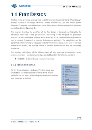
  • 1. 1 4 U S E R M A N U A L 3 0 1 w w w . c o n s t e e l s o f t w a r e . c o m 11 FIRE DESIGN The Fire design process is an integrated part of the Consteel automated and efficient design process. In case of fire design situation Consteel automatically uses and applies propel formulas of EuroCode for steel elements. General information about the design functionalities can be found in the CHAPTER 9. This chapter describes the workflow of the Fire design in Consteel and highlights the differences compared to the general rules. Depending on the designed fire protection solution, the structure can be unprotected or protected, in the latter case the fire protection can be passive (insulation) or reactive (intumescent painting). The calculation can be performed with material properties at elevated or room temperature. In the case of elevated temperature analysis, the indirect effects of thermal expansion can also be considered separately. The required code checks of the different types of steel structural components – cross sections, members – can be conveniently evaluated based on the following standard: EN 1993-1-2: General rules. Structural fire design 11.1 FIRE LOAD GROUP For fire design situation, a dedicated Fire load group was created that handle the specialties of fire effect. Before specifying the fire effect, a fire load group and at least one fire load case must be defined.
  • 2. 1 4 U S E R M A N U A L 3 0 2 w w w . c o n s t e e l s o f t w a r e . c o m Fire load group has more options: Analysis with room temperature material properties - this calculation method must be chosen to check the structure with reactive protection (intumescent paint). Analysis with elevated temperature material properties - for the check of structures with passive protection (e.g. gypsum insulation) or without any protection. The stresses and displacements are determined based on the required fire resistance time. o Consider indirect actions caused by thermal expansion: By default, Consteel neglect the effect of thermal expansion during the analysis, but by clicking on the checkbox there is the possibility to take it into account. Value of variable factor for main variable load: By default, Consteel applies the Ψ2,1 but switching the radio button Ψ1,1 also can be used for load combination generation. At least one load case must be added to the fire load group to place the fire effect on the model.
  • 3. 1 4 U S E R M A N U A L 3 0 3 w w w . c o n s t e e l s o f t w a r e . c o m 11.2 FIRE EFFECT AND PROTECTION The fire effect and protection can be defined by clicking the DEFINE FIRE EFFECT AND FIRE PROTECTION ( ) icon on the LOADS tab. The first option is to set the nominal fire curve. Three EuroCode defined fire curves are implemented and can be used to define fire effect: Standard, External and Hydrocarbon. The second one is to set the fire resistance time that can be varied between 15-200 min. By clicking on the three-dot button next the Fire protection data label, different fire protection can be created. Fire protection can be Unprotected and Protected. If Protected is chosen, the protection can be passive or reactive. Passive protection: the insulation material and the thickness must be specified. From the dropdown menu, the section grading for fire effect, according to EN 1993-1-2-4.5. chapter also must be selected.
  • 4. 1 4 U S E R M A N U A L 3 0 4 w w w . c o n s t e e l s o f t w a r e . c o m Reactive protection: this should be selected if the fire protection of the given structure (part) will be provided by an intumescent paint coating and the critical temperature calculation is required to select the paint. ATTENTION! CRITICAL TEMPERATURE CALCULATION CAN ONLY BE REQUESTED FOR MEMBERS THAT HAVE REACTIVE PROTECTION! Finally, in the lowest drop-down menu of the dialog box, for any protected or unprotected type, the section grading of the structural element acc. to EN 1993-1-2 - 4.2.5. / 4.2 and 4.3. should be specified. By clicking on the APPLY button, fire protection will be saved. With the NEW button, several other protections can be created. With DELETE button, the selected and created protection can be removed. The fire effect can be set to a different intensity at the top and the bottom of the member by modifying Ψ1 and Ψ2 multiplication factors. In case of varying intensity, the design parameters acc. to the EN 1993-1-2 4.2.3.3 (7)-(8) also can be set. Created fire effect can be placed on the members with a simple click on the model. It is possible to apply fire effect to more members at the same time. This case the members should be selected before clicking the fire icon. 11.3 ANALYSIS During the finite element generation Consteel calculates the steel temperature and the reduced modulus of elasticity. These values can be viewed in the FINITE ELEMENT tab by selecting the appropriate load case.
  • 5. 1 4 U S E R M A N U A L 3 0 5 w w w . c o n s t e e l s o f t w a r e . c o m The analysis for the fire load combinations are performed in global level. Therefore, the calculated deformations and internal forces possibly include the effect of the expansion and decreased elasticity modulus of those members which are subjected to fire. 11.4 DESIGN 11.4.1 FIRE DESIGN ON ELEVATED TEMPERATURE Consteel performs cross section resistance and buckling checks for all steel members which are subjected to fire effect by using the adequate formulas from the EuroCode 3 standard. Classification of cross-section (EN 1993-1-2 4.2.2) Cross-sections are classified as for normal temperature (EN 1993-1-1) but using the reduced value for ε. 𝜀 = 0,85 ∙ [ 235 𝑓𝑦 ] 0,5 Tension (EN 1993-1-2 4.2.3.1) Permanent temperature ((1)) (Class 1-4) where  , y k value based on a function according to Table 3.1 Rd , pl N based on normal case Varying temperature ((2)) Rd . pl fi , M 0 , M , y Rd , , fi , t N k N   =    
  • 6. 1 4 U S E R M A N U A L 3 0 6 w w w . c o n s t e e l s o f t w a r e . c o m fi , M y t , non Rd , t , fi , t f A N   = (Class 1-4) Compression (Class 1-3: EN 1993-1-2 4.2.3.2, Class 4: + Annex E.2) Permanent temperature ((1)) fi M y y Rd t ft c f k A N , , , , ,     = (Class 1-3) fi , M y , 2 . 0 p eff Rd , t , fi , c f k A N     = (Class 4) where  , 2 . 0 p k value based on a function according to Table 3.1 Varying temperature ((6)) Conservative way, case (1) where max , a a   = Bending (EN 1993-1-2 Class 1-2: 4.2.3.3; Class 3: 4.2.3.4; Class 4: + Annex E.2) Permanent temperature ((1)) Rd fi , M 0 , M , y Rd , , fi M k M   =     where Rd . pl Rd M M = or in case of shear Rd . V Rd M M = (Class 1-2) Rd . el Rd M M = or in case of shear Rd . V Rd M M = (Class 3) Rd . eff Rd M M = (Class 4)  , y k value based on a function according to Table 3.1 Varying temperature ((2)) fi , M y t , non , pl Rd , t , fi f W M   = (Class 1-2) Rd , el 2 1 fi , M 0 , M max , , y Rd , t , fi M 1 k M         = (Class 3) where 7 , 0 1 =  if protection=1 and m_factor_section=2,3 or 10 85 , 0 1 =  if protection=2 and m_factor_section=3 or 4 0 , 1 1 =  in other cases 0 , 1 2 =  conservative Rd , eff 2 1 fi , M 0 , M max , , 2 . 0 p Rd , t , fi M 1 k M         = (Class 4)
  • 7. 1 4 U S E R M A N U A L 3 0 7 w w w . c o n s t e e l s o f t w a r e . c o m Shear (EN 1993-1-2 Class 1-2: 4.2.3.3(6); Class 3: 4.2.3.4(4); Class 4: + Annex E.2) Permanent temperature Rd fi , M 0 , M web . , y Rd , t , fi V k V   =    (Class 1-4) Varying temperature web , , y k  the hottest point in the web In case of complex internal forces Consteel uses the conservative interaction formula neglecting the effect of shear: 1  + + Rd , , fi , z Ed , fi , z Rd , , fi , y Ed , fi , y Rd , , fi Ed , fi M M M M N N    Global stability resistance To calculate the global stability resistance for fire design situation, Consteel uses EuroCode General method (EN 1993-1-1 6.3.4) as for normal temperature but using the proper buckling curves: For compression 𝜒𝑓𝑖 = 1 𝜑𝜃 + √𝜑𝜃 2 − 𝜆̅𝜃 2 For bending 𝜒𝐿𝑇,𝑓𝑖 = 1 𝜙𝐿𝑇,𝜃,𝑐𝑜𝑚 + √𝜙𝐿𝑇,𝜃,𝑐𝑜𝑚 2 − 𝜆̅𝐿𝑇,𝜃,𝑐𝑜𝑚 2 11.4.2 CRITICAL TEMPERATURE CALCULATION The critical temperature calculation can be activated in the design settings window. This option is only active if the following conditions are met at least one member with passive fire protection at least one fire load case set to room temperature analysis at least one load combination with fire load case is selected for global design
  • 8. 1 4 U S E R M A N U A L 3 0 8 w w w . c o n s t e e l s o f t w a r e . c o m The results of the calculation can be queried in the Design Parameters drop-down menu. The results are displayed in a colored graphic. You can also open the SECTION MODULE from here by right-clicking on a given section, where the details of the critical temperature calculation can be found. The first line of the summary reads whether the profile should be protected or not, and the critical temperature field contains the relevant part of EC, the applied fire curve, the unprotected fire resistance time and temperature reached of the profile and the required fire resistance time.
  • 9. 1 4 U S E R M A N U A L 3 0 9 w w w . c o n s t e e l s o f t w a r e . c o m
  • 10. 1 4 U S E R M A N U A L 3 1 0 w w w . c o n s t e e l s o f t w a r e . c o m 12 EARTHQUAKE ANALYSIS 12.1 BASICS Consteel can perform earthquake analysis is based on Modal response spectrum analysis (MRSA), and it supports three different analysis types: ▪ All modal shapes, CQC summation: Consteel calculates the modal loads for all dynamic shapes, for all directions, and calculates the analysis results (displacements, internal forces) for each dynamic shape using first order analysis. After this, it summarizes them with Eurocode’s CQC method. CQC summation method can give the highest expectable deformations and internal forces, based on a statistical method. Envelope diagrams of deformation and internal forces without signs are the result of the CQC summation ▪ Single dominant mode: From the calculated dynamic shapes, Consteel chooses the dominant one for each direction, and performs the calculation for one dominant shape for each direction. Modal loads for each direction are the results of the method. ▪ Selected modes, linear summation: With the modal shapes, chosen by the user, and with the combination factors for each shapes Consteel creates a linear combination of vibration shapes, and gives the results for all directions using the combined shapes. Modal loads for each direction are the results of the method. Comparison of the three methods: All modal shapes, CQC summation Single dominant mode Selected modes, linear summation Dynamic calculation Required Required Required Second order analysis Not possible Yes Yes Stability calculations Not possible Yes Yes Global check – Cross section check Yes Yes Yes Global check – Stability check Not possible Yes Yes
  • 11. 1 4 U S E R M A N U A L 3 1 1 w w w . c o n s t e e l s o f t w a r e . c o m Member check Not possible Yes Yes Masses taken into consideration Masses corresponding for each vibration shapes for all directions Masses for the chosen vibration shapes with the consideration of the combination factors in all directions 100% of the masses in all directions Automation Yes Manual input required Yes Second order sensitivity Yes Yes Yes Results of the modal response spectrum analysis with the 100% „+” 30% rule are combined with the other effects acting in seismic situation, by Consteel. 12.2 STEPS OF THE SEISMIC ANALYSIS Modal response spectrum based seismic analysis can be performed with the following steps in Consteel: 1. Definition of modal loads/Mass tab ▪ Definition of mass cases and mass groups ▪ Mass definition manually on the structure, or by converting existing load cases ▪ Mass combination definitions 2. Seismic effect definition/Masses tab ▪ Definition of Standard or User defined response spectrum ▪ Definition of Seismic effect ▪ Setting the analysis method 3. Seismic load group and load combination definition / Loads tab ▪ Seismic load group and loadcase creation ▪ Assignment of seismic effect to seismic loadcase
  • 12. 1 4 U S E R M A N U A L 3 1 2 w w w . c o n s t e e l s o f t w a r e . c o m ▪ Definition of considered shapes for the analysis – Only in the case of Selected modes, linear summation analysis method! 4. Analysis / Analysis tab ▪ Setting the statical calculation parameters; For the comparison of available analysis types, please check chapter 13.1 ▪ Setting the parameters for Dynamic calculations 5. Design / Global checks and Member checks tab ▪ For the available design checks, please go to the comparison of different analysis types at chapter 13.1 12.3 SEISMIC EFFECT Seismic effects can be created with the SEISMIC EFFECT ( ) function which can be found on the MASS tab. On the Seismic effect dialogue, all parameters can be set, which are required for the seismic analysis. For the seismic effect creation, existence of pre-created mass combination and response spectrum is required. To see how to define these, please go to CHAPTER 7 MASSES! New seismic effect can be created by pressing the NEW button. More seismic effects can be created and saved. Change between different saved seismic effects is possible with the Name dropdown menu. Options of the SEISMIC EFFECT dialogue has been separated into two tabs: ▪ Seismic settings ▪ Additional effects 12.3.1. SEISMIC SETTINGS In the Settings (#1) panel, main parameters of the seismic analysis can be set ▪ Mass combination: Choice of the used mass combination for the dynamic shape evaluation during the modal response spectrum analysis must be done. The dropdown menu is automatically filled up with the pre-defined mass combinations. Seismic analysis will only be performed for the mass combination which is selected here! ▪ Calculation method: Choice of the calculation method to be used for the seismic analysis. To see the differences between each calculation methods, please see chapter 12.1
  • 13. 1 4 U S E R M A N U A L 3 1 3 w w w . c o n s t e e l s o f t w a r e . c o m ▪ Main direction of the structure from X: The main direction of the structure can be set using the black arrow () tool, by clicking the start and end point of a vector in the modelling area. The other option is to set the angle between the main direction and the X axis manually in the edit box with direct input. The direction, which is given will be the „1” direction, perpendicularly to this will be the „2” direction of the effect. The q1 and q2 factors corresponds with these directions too. On the response spectrums panel (#2), the response spectrum can be selected which will be used for the seismic analysis. 2 3 1 4
  • 14. 1 4 U S E R M A N U A L 3 1 4 w w w . c o n s t e e l s o f t w a r e . c o m Handling of the response spectrums in ultimate and serviceability limit states can be the following: ▪ ULS response spectrum, and use of qd factors In this case choice of response spectrum (standard or user defined) is possible only for the ULS checks. Deformations, which are necessary for the SLS checks are evaluated from the ULS results, using the qd displacement behavior factors ▪ response spectrum for ULS and SLS limit states Choosing the Elastic response spectrum for SLS option, different response spectrum can be set for ULS and SLS limit states. For ULS limit state, only standard or user defined design spectrum, while for SLS limit state only standard or user defined elastic response spectrum can be chosen from the dropdown menu Clicking on the ( ) button will bring up the spectrum definition dialogue, where parameters of a spectrum can be checked, or even new ones can be created (see CHAPTER 7.6 CREATING RESPONSE SPECTRUMS) At the Behavior factors (#3) panel, behavior and displacement behavior factors can be set for the main directions (1,2,z). Number of adjustable behavior factors are depending of the type of the applied response spectrum(s): Behavior factor (q) Displacement behavior factor (qd) ULS design spectrum and qd factors for SLS Adjustable in case of standard response spectrum In case of user defined spectrum, the spectrum itself contains it, cannot be adjusted Adjustable
  • 15. 1 4 U S E R M A N U A L 3 1 5 w w w . c o n s t e e l s o f t w a r e . c o m Different response spectrum for ULS and SLS limit states Adjustable in case of standard response spectrum In case of user defined spectrum, the spectrum itself contains it, cannot be adjusted Cannot be adjusted Behavior factors besides the type of the spectrum, are dependent on the following options: ▪ Consider vertical seismic effect: If the option is turned on, vertical behavior factors can be set, and vertical seismic effects will be taken into consideration for the seismic analysis ▪ Same behavior in Horizontal XY directions: If the option is turned on, it is enough to define only one behavior parameter, it will be applied for both X and Y directions At the bottom of the dialogue, in the Shown response spectrum panel (#4) the selected response spectrum –design or elastic- of the dropdown menu can be seen. By hovering the mouse over the points of the graph, its value will be displayed graphically. 12.3.2. ADDITIONAL EFFECTS On the ADDITIONAL EFFECTS tab of the SEISMIC EFFECT dialogue, the following settings can be adjusted: ▪ Accidental torsional effects: In case of spatial 3D models, effects of the uncertainties of load placements causing torsional effects and must be considered. Consteel calculates the effect automatically. For the calculation, storeys have to be defined, where torsion effect is acting, and eccentricity value, with which the mass points will be shifted. ▪ Second order effect: Second order effects must be taken into account, if the coefficient of the shift difference (θ) between the storeys is greater than 0,1. Consteel automatically calculates it and takes it into account. Storeys has to be pre-defined. Considered storeys has to be chosen in the Considered storeys for accidental torsional and second order effects (#1) panel. If there are storeys defined in the model (see CHAPTER 3.4 PORTION MANAGER), they will be automatically loaded into the table. If the checkbox is turned on next to a storey, it will be taken into consideration during the seismic analysis.
  • 16. 1 4 U S E R M A N U A L 3 1 6 w w w . c o n s t e e l s o f t w a r e . c o m WHEN SPECIFYING THE LEVELS, IT IS IMPORTANT TO KNOW THAT CONSTEEL TAKES THE WEIGHTS OF THE STRUCTURE BELOW THE LOWEST LEVEL ALL OF THEM TO THE LOWEST LEVEL BY THE TORSIONAL AND SECOND ORDER EFFECTS. THIS CAN BE AVOIDED BY ESTABLISHING A LEVEL 0 IN THE PLANE OF THE SUPPORTS, SO THE WEIGHT DISTRIBUTION BETWEEN THE SUPPORT AND THE FIRST LEVEL WILL ALSO BE PERFORMED. At the Accidental torsional effects (#2), consideration of the effect can be turned on or off. The following combinations can be chosen for the shift of the mass points: ▪ +eaX+eaY, - eaX-eaY: Mass points will be shifted both for positive and negative directions in the global X and Y directions with the given value, but not mixed. It is a simplification, and it is reducing the number of seismic combinations ▪ +eaX+eaY, +eaX-eaY, -eaX+eaY, - eaX-eaY: Mass points will be shifted both for positive and negative directions in the global X and Y directions, including mixed signs too, with the given value. It is the recommended way by Eurocode, but it increases the number of seismic combinations. The value of the shift of the mass points can be given in the edit box with a percentage. 2 1
  • 17. 1 4 U S E R M A N U A L 3 1 7 w w w . c o n s t e e l s o f t w a r e . c o m 12.4 SEISMIC LOADCASES AND LOAD COMBINATIONS 12.4.1. SEISMIC LOAD GROUP AND LOADCASE Going back to the LOAD CASES AND LOAD GROUPS dialogue, a new type of SEISMIC LOAD GROUP has to be defined. After creating a seismic load group, the pre-defined seismic loadcase will automatically assigned to the group as a seismic loadcase. If the calculation method for the seismic effect is set to SELECTED MODES, LINEAR SUMMATION, an additional button will appear on the LOAD CASES AND LOAD GROUPS dialogue when the seismic loadcase is selected in the tree control. The LINEAR COMBINATION OF MODAL EFFECTS (#1) button stands for the option to set the combination factors for the calculated vibration shapes. After clicking on the button, a new dialogue will pop-up, which contains all the calculated vibration shapes, with the corresponding mass participation for each one, in all (1,2,z) main directions. By setting the combination factors, mass participation can be adjusted for each vibration modes, 1 which will be considered during the next seismic analysis. If all the combination factor cells of the table are empty, Consteel will perform seismic analysis with SINGLE DOMINANT MODE calculation method.
  • 18. 1 4 U S E R M A N U A L 3 1 8 w w w . c o n s t e e l s o f t w a r e . c o m 1
  • 19. 1 4 U S E R M A N U A L 3 1 9 w w w . c o n s t e e l s o f t w a r e . c o m 12.4.2. LOAD COMBINATIONS IN SEISMIC DESIGN SITUATIONS On the AUTOMATIC GENERATION OF LOAD COMBINATIONS dialogue, all combinations can be automatically generated for seismic situations too, including ultimate and serviceability limit states.
  • 20. 1 4 U S E R M A N U A L 3 2 0 w w w . c o n s t e e l s o f t w a r e . c o m 13 DOCUMENTATION 13.1 BASICS In Consteel there is a powerful and easy-to-use documentation engine to create precise, easily editable static documents that meet the requirements of the structural engineers. The static documentation contains the full description of the model and the results of the analysis and design. 13.2 THE DOCUMENT TAB 13.2.1 START DOCUMENTATION All icons which related to the documentation are placed in the DOCUMENT tab. The documentation can be generated if first icon is clicked. The documentation wizard guides you through the documentation generating process. On the first window the name of the documentation can be set. The name appears on every page of the documentation. Other fields like the name of the project, the name of the engineers and the date of the creation can also be set but would appear only on the front page.
  • 21. 1 4 U S E R M A N U A L 3 2 1 w w w . c o n s t e e l s o f t w a r e . c o m The header and the footer pictures of the document can be customized so your own company logo can be added. To do so the default header and footer images need to be replaced. These files can be found in the software’s installation directory; the default path is the following: C:Program FilesConSteelversionPic. The “Header_pic.png” and the “Footer_pic.png” need to be replaced by your own images. The second step is to choose which of the analysis results need to be included in the documentation. Any of the analysis results can be chosen if had been calculated previously.
  • 22. 1 4 U S E R M A N U A L 3 2 2 w w w . c o n s t e e l s o f t w a r e . c o m The third window of the wizard includes the name of the chapters which can be added to or can be removed from the documentation. For the ULS design documentation utilization limit can be set at the bottom of the dialog. All the members will be included the generated documentation that are equal or higher than the set limits. Separate limits can be set for the summary and for the detailed documentations. Documentation templates can be saved with the SAVE button. Most used documentation structures can be saved as templates. Based on the templates, documentation can be created with one click. If you click on the CREATE button the program will generate the documentation. 13.2.1.1 DOCUMENTATION MODULE After creating the documentation, it will be opened in a new window. At the top right of the window the chapters can be seen. The chapters can be moved up or down by drag-and-drop function. It is also possible to delete content from document by clicking the third icon (#2). Text can be inserted anywhere in the document if you click on the fourth icon (#3) and type in the desired text into the window. It is also possible to insert headings by clicking on the fifth icon (#4). You can also insert page break anywhere in the document using the sixth icon (#5). The last three icons can be used for the following purposes: Edit heading and increase or decrease level of heading. 1 2 3 4 5 6
  • 23. 1 4 U S E R M A N U A L 3 2 3 w w w . c o n s t e e l s o f t w a r e . c o m The last two icons on the right are different if you click on a chapter or in a paragraph. If you click on a chapter, then the icons are as described above. If a paragraph is clicked where there is a table, the last icon can be used to delete any column from the table. If you click on a paragraph which contains text, then the last two icons on the right can be used to edit the paragraph content and the alignment. With the first two icons (#1) the fitting of the pages can be set. Pages can be fit with width ( ) or with height ( ). By clicking the Pictures tab, the image handling icons can be seen. Any of the taken snapshots can be inserted into the documentation or can be deleted. The image will be inserted below the selected paragraph. The third tab is the Tables. There are lot of possibilities in Consteel where tables can be saved. If you see the icon during analysis and design process where the results appear in a table,
  • 24. 1 4 U S E R M A N U A L 3 2 4 w w w . c o n s t e e l s o f t w a r e . c o m then that table is saveable. Any previously saved tables can be inserted to the documentation or can be deleted from the model database. The table will be inserted below the selected paragraph. The last tab is the Appendices. If any joint or section documentation had been generated previously, these can be found here and can be added to the end of the documentation. The appendices can also be deleted from the database. IT SHOULD BE BEAR IN MIND THAT THE DOCUMENTATION NEED TO BE REGENERATED TO BE UP TO DATE AFTER ANY CHANGES HAS BEEN MADE ON THE MODEL. IF THERE ARE SNAPSHOTS IN THE DOCUMENTATION THESE SNAPSHOTS SHOULD BE TAKEN AGAIN AND NEED TO BE ADDED TO THE DOCUMENTATION. 13.2.2 CREATING SNAPSHOTS The second icon on the DOCUMENT tab can be used to take a snapshot of the model. The snapshots can be easily added to the desired part of the documentation (see 11.2.1.1 chapter for detailed information). The size of the snapshot can be set, and a dashed rectangle shows which part of the model would appear on the picture. The model can be moved or rotated to fit into the dashed rectangle. With the PRINT button the actual view of the model can be printed directly from the dialog.
  • 25. 1 4 U S E R M A N U A L 3 2 5 w w w . c o n s t e e l s o f t w a r e . c o m 13.2.3 SNAPSHOT MANAGER The third icon on the documentation tab is the Snapshot manager where the taken snapshots can be exported to a file or can be deleted from the model (except if the picture was inserted into the documentation) in order to reduce model file size. Multiple selected pictures can be saved and deleted at the same time. The name of the images can also be edited by double clicking the name of the image.
  • 26. 1 4 U S E R M A N U A L 3 2 6 w w w . c o n s t e e l s o f t w a r e . c o m 13.2.4 MODEL INFORMATION With using the fourth icon on the DOCUMENT tab the model information can be viewed or can be exported to a file. The model information window shows the most important features of the model like Number of bars, Number of supports, Total weight of the structure, etc. The mass, surface and the length can be viewed for each section in the model. The model information can be shown based on the full model or on the current view if the model view shows only a part of the full model using the sub model view. 13.3 MS WORD EXPORT OF THE DOCUMENTATION Documentations can be exported into an editable .docx format Word file. The export itself is a complete process, which means every table, picture and appendices will be exported. The MICROSOFT WORD export function can be found in the documentation module’s DOCUMENT menu, under the EXPORT submenu.
  • 27. 1 4 U S E R M A N U A L 3 2 7 w w w . c o n s t e e l s o f t w a r e . c o m After pressing the MICROSOFT WORD button, the Documentation export dialogue will appear: On the dialogue the path of the exported file must be given, by browsing it with the (…) button. It is available (and required) to choose a TEMPLATE for the exported document. Templates are a collection of styling settings, which will be applied on the exported Word file. By default, a Consteel template is provided in the installation package, and it contains the same styling settings as the main Consteel documentation. By selecting the USE CONSTEEL TEMPLATE, and pressing the OK button, Consteel will generate a Word file of your documentation, which is the same in content, and is as close as it can be in styling as the original one. Custom templates can also be used, please check CHAPTER 13.3.1 to know more! When opening an exported documentation in Word for the first time, the table of content has to be refreshed, by right clicking on the heading of the table and pressing the refresh button:
  • 28. 1 4 U S E R M A N U A L 3 2 8 w w w . c o n s t e e l s o f t w a r e . c o m 13.3.1 CREATING CUSTOM TEMPLATES FOR MS WORD EXPORT As it was mentioned in the previous chapter, the installation package of Consteel contains a default template, which is filled up with the same styling settings, as the main documentation. This template can be found in the installation folder of Consteel, which is “C:Program FilesConsteel 13DataExportConsteel.dotx” by default. If a new template, with customized styling settings is desired to be created, the Consteel.dotx file should be copied first. After opening the copied file, the change in stylings can be performed in the STYLES dialogue of MS Word: After the settings are made, the file should be saved in .dotx format (as the original was), and it can be used for word exports in the future.
  • 29. 1 4 U S E R M A N U A L 3 2 9 w w w . c o n s t e e l s o f t w a r e . c o m 14 JOINT MODULE 14.1 BASICS In the Consteel design approach great emphasis is placed on the integrated modelling and calculation of the global structure and its connections therefore a powerful joint analysis engine is developed as a separate module: csJoint. A great range of different joint types can be created easily applying several special connection elements, the design tools covers practically the whole joint standard Eurocode 3 Part 1-8. A joint can be defined alone or based on the global model by the automatic joint identification tool. A prepared joint can be placed several different places in the global model to make the joint integral part of it. A placed joint is always automatically rechecked based on the current analysis results, and the connection stiffness is also updated modifying the global model consequently. All the joint related commands can be found on the STRUCTURAL MEMBERS tab. These are the followings: Edit joint, Create joint by model, Place joint. 14.2 JOINT TYPES The number of the joint types is one of the most dynamically developing parts of the software, usually considering the claims of the users. The module offers a number of strengthening possibilities such as: lower or/and upper haunch with or without flange, transverse web stiffeners, flange stiffeners and flange backing plates, shear stiffeners (supplementary web plate, Morrison stiffener, single or double skew plate stiffener) etc. At the moment the CSJOINT module has the following joint and connection types:
  • 30. 1 4 U S E R M A N U A L 3 3 0 w w w . c o n s t e e l s o f t w a r e . c o m
  • 31. 1 4 U S E R M A N U A L 3 3 1 w w w . c o n s t e e l s o f t w a r e . c o m
  • 32. 1 4 U S E R M A N U A L 3 3 2 w w w . c o n s t e e l s o f t w a r e . c o m
  • 33. 1 4 U S E R M A N U A L 3 3 3 w w w . c o n s t e e l s o f t w a r e . c o m 14.3 CREATE JOINT 14.3.1 CREATE JOINT WITHOUT MODEL Joint models can be created without global model by clicking on the EDIT JOINT icon on the STRUCTURAL MEMBERS tab. In this case the joint type, geometry and the loads need to be set manually. One of the advantages of Consteel, that in csJoint it is possible to handle several connections inside of a joint. By this, a large scale of customized joints can be designed. In the following, a creation of a beam-to-column joint will be demonstrated.
  • 34. 1 4 U S E R M A N U A L 3 3 4 w w w . c o n s t e e l s o f t w a r e . c o m Step 1 - Joint identification After clicking on the CREATE button ( ) on the top left corner the name of the joint must be given. Comment for the joint can be optionally given, and Default settings of the joint can be modified (see later in CHAPTER 14.3.5 DEFAULT JOINT SETTINGS). Step 2 – Joint configuration The type of the joint has to be defined on the next dialog. csJoint can handle great variety of joint types, which covers nearly the whole joint standard Eurocode 3 Part 1-8. (see joint types in CHAPTER 14.2)
  • 35. 1 4 U S E R M A N U A L 3 3 5 w w w . c o n s t e e l s o f t w a r e . c o m Step 3 – Connections configuration Here (picture above) it is possible to set connections both to the flanges (#1) and the web (#2). For eligible list of connections, please see CHAPTER 14.2. In this dialog, the section of the column is also has to be set. It can be chosen from the drop-down menu or loaded from the section administrator by clicking the three-dot button ( ). When setting a connection (picture above), the type (#1) and the cross section of the connected element (#2) has to be set. It can be chosen from the drop-down menu or loaded 1 2 3 1 2
  • 36. 1 4 U S E R M A N U A L 3 3 6 w w w . c o n s t e e l s o f t w a r e . c o m from the section administrator by clicking the three-dot button ( ). For eligible list of connections, please see CHAPTER 14.2. After the desired connections have been set (picture below), by clicking the CREATE button the joint will be created. Joint loads can be given manually, and the manipulations of the connection elements can be made as a last step.
  • 37. 1 4 U S E R M A N U A L 3 3 7 w w w . c o n s t e e l s o f t w a r e . c o m For complete information about manipulating the connection, please see CHAPTER 14.3.4 MANIPULATING CONNECTIONS. 14.3.2 CREATE JOINT BY MODEL Creating joint by the model is simple and easy. Just click on the CREATE JOINT BY MODEL button and select the joint. The members will be automatically identified, and the possible connection types are offered. Here is possibility to remove some members from the identified connection by removing the appropriate tick.
  • 38. 1 4 U S E R M A N U A L 3 3 8 w w w . c o n s t e e l s o f t w a r e . c o m 14.3.3 PLACE JOINT IN THE GLOBAL MODEL After creating the joint it is advisable to place it in the global model. There are two options to do this: The fastest way of placing a joint, is to place it from the JOINT DETAILS dialog directly, right after when it is been created. PLACE… button can be found at the bottom left corner of JOINT DETAILS dialog (see picture below). By choosing it, it is possible to place the joint to several places by single clicks on the 3D structural model where the same geometry exists. By clicking END JOINT PLACEMENT button (see picture below), loads will automatically be imported from the model if analysis results are available.
  • 39. 1 4 U S E R M A N U A L 3 3 9 w w w . c o n s t e e l s o f t w a r e . c o m The other way of placing a joint, is to use PLACE JOINT function, which can be found on the STRUCTURAL MEMBERS tab. This function is useful when more previously created joints have to be placed. One joint can be placed to several places in the model where the same geometry exists. After the joint is placed, csJoint automatically import the loads from the global model if analysis results are available. IT SHOULD BE BEAR IN MIND THAT THE SETTINGS IN THE CSJOINT MODULE (PROFILES SIZES, MATERIAL GRADES, ETC.) WILL NOT AFFECT THE 3D MODEL. THE CHANGED VALUES WILL BE CONSIDERED IN THE JOINT CALCULATION ONLY! THE USER HAS TO WAY TO KEEP THE MODEL CONSISTENT: 1. AFTER MODIFYING THE CONNECTION THE 3D MODEL HAS TO BE CHANGED ACCORDINGLY, 2. CHANGE THE 3D MODEL FIRST RUN THE ANALYSIS, REDEFINE THE CONNECTION. 14.3.4 MANIPULATING JOINTS No matter if a joint is created with or without model manipulating the joint is the same. Joint details appear in a new window where numerous settings can be made. In the following pages we would like to give an overview of the csJoint module using a beam-to-column connection as an example. Select the joint from the tree structure on the JOINT dialog, and press DETAILS ( ) button, or double click on the name of the joint.
  • 40. 1 4 U S E R M A N U A L 3 4 0 w w w . c o n s t e e l s o f t w a r e . c o m 14.3.4.1 JOINT DETAILS DIALOG After the creation of a new joint, or opening an existing one for modification, the JOINT DETAILS dialog appears, which can be separated into four parts. The window contains the general information about the joint: Joint name, project, engineer, date, etc. These properties will appear in the joint documentation and also useful to distinguish joints from each other.
  • 41. 1 4 U S E R M A N U A L 3 4 1 w w w . c o n s t e e l s o f t w a r e . c o m (#1) The first part shows the tree structure about the joint: all components of the connection can be seen and selected. (#2) On the second part, the selected component related information / properties can be seen and set: Joint name, project, engineer, date, etc. These properties will appear in the joint documentation and also useful to distinguish joints from each other. (#3) The third part is the graphical window. Predefined views of the joint can be selected with the view tools: (#4) The fourth part shows the results of the joint calculation. Calculation is automatically run when any changes take place and the AUTOMATIC CALCULATION checkbox is clicked. If the checkbox is unchecked the calculation can be run with the CALCULATION button. In the pull-down menu the type of the result visualization can be set to three different types: ▪ Summary for the whole joint ▪ Summary for the selected connection ▪ Detailed results of the selected connection In the last two cases a connection must be chosen in the connection tree. 1 2 3 4
  • 42. 1 4 U S E R M A N U A L 3 4 2 w w w . c o n s t e e l s o f t w a r e . c o m Documentation of the Joint can be started with the DOCUMENT… button on the bottom left corner of the dialog. 14.3.4.2 MANIPULATING JOIN Column If the Column is selected in the connection tree, then column related properties of the connection can be set like the section size and material grade (#1). Setting the position of the column is also very important (#2). Furthermore, the position of the reference plane is essential for the joint calculation. The image on the right gives a visual help about the meaning of ‘Lsr’ and ‘Lc’ variables. Stiffeners Stiffeners can be added if Stiffeners is clicked in the connection tree. Upper and lower stiffener plate properties can be seen in the #1 part of the image below. Additional web and flange stiffeners can also be defined (#2). In order to place shear stiffener in the joint click on ‘Use stiffener’ check box (#3). Bear in mind that the position of the stiffeners are measured from the reference plane of the beam, which can be set if the Beam is clicked in the joint tree (see below!). 1 2 3
  • 43. 1 4 U S E R M A N U A L 3 4 3 w w w . c o n s t e e l s o f t w a r e . c o m Joint loading If Joint loading is selected, it is possible to choose from two options (#1). When “User defined joint loading” is selected, joint loads can be given manually by defining load cases, and internal forces (#2). If “Model based joint loading” is selected, csJoint automatically imports the internal forces from all of the combinations after the joint is placed in the modelling area. 1 2 3 1 2
  • 44. 1 4 U S E R M A N U A L 3 4 4 w w w . c o n s t e e l s o f t w a r e . c o m Beam If the Beam is selected in the connection tree, then beam related properties of the connection can be set like the section size and material grade (#1). Beam end configuration can be set such as haunch (#2). Furthermore, the beam span and position of the beam are essential for the joint calculation (#3). End plate End plate properties (geometry, material) can be edited in the #1 part of the image below. Bolt properties can be seen on #2 part. 1 2 3
  • 45. 1 4 U S E R M A N U A L 3 4 5 w w w . c o n s t e e l s o f t w a r e . c o m Welds At Welds, it is possible to choose if welds should be optimized automatically or not (#1). If not, weld properties can be set manually (#2). Method of weld design also can be set in this window (#3) 1 2 1 2 3
  • 46. 1 4 U S E R M A N U A L 3 4 6 w w w . c o n s t e e l s o f t w a r e . c o m Any changes made on the joint will take place either when pressing ENTER or by clicking to another editable field on the window. If Automatic calculation is turned on and any changes take place, then the calculation of the joint is automatically rerun. It can be turned off. In that case click on the CALCULATION button to run the calculation. In the pull-down menu the type of the result visualization can be set to three different types: Summary for the whole joint, Summary for the selected connection, Detailed results of the selected connection. In the last two cases a connection must be chosen in the connection tree. The result of the joint calculation can be seen in the highlighted part of the window. If the detailed result is selected, then all the results of the necessary calculations can be seen according to the selected load combination or according to the dominant load case. 12.3.5 DEFAULT JOINT SETTINGS The default joint setting like weld sizes, bolt diameter, etc. can be changed and saved. Default joint settings can be changed and saved by clicking the DEFAULT JOINT SETTINGS ( ) icon on the JOINTS dialog.
  • 47. 1 4 U S E R M A N U A L 3 4 7 w w w . c o n s t e e l s o f t w a r e . c o m The default joint configuration file is saved to the DocumentsConsteel folder as UserConfig.xml. 14.4 ANALYSIS OF CONNECTIONS All the analysis in CSJOINT module is based on the standard procedures of Eurocode 3 Part 1- 8, these procedures are almost entirely covered by the module. For the different types of connections, the following analyses are performed: Moment connections: • Moment resistance based on the plastic tension components of the individual or grouped bolt rows and compression components including the effect of axial load • Shear resistance of the bolts in combined shear and tension • Bearing resistance of plates • Web and flange weld resistance and capacity to the applied load, the section strength or the appropriate component • Initial and secant stiffness based on the tension and compression components and applied moment Shear connections: • Shear resistance of bolts and plates • Bearing resistance of plates
  • 48. 1 4 U S E R M A N U A L 3 4 8 w w w . c o n s t e e l s o f t w a r e . c o m • Block tearing resistance of plates • Weld resistance and capacity to the applied load or section strength Hollow section connections: • Chord face failure, web failure, shear failure and punching shear failure • Brace failure • Local buckling of the members 14.5 RESULTS AND DOCUMENTATION The analysis results are displayed in two main forms: a summarized view containing the main resistances, stiffness and capacities; and a detailed view showing the components of the main results which is comprehensive enough to see what are the weakest point of the connections and what type of strengthening would be the most efficient to apply. A joint is calculated for all the loads coming from different places or different combinations, and the dominant place and combination is automatically highlighted. The spectacular documentation shows the detailed geometry of the joint with its connections, and the summarized and detailed results for all cases can be flexibly documented.
  • 49. 1 4 U S E R M A N U A L 3 4 9 w w w . c o n s t e e l s o f t w a r e . c o m The way for creating documentation is the same as in Consteel main module (see Chapter 11 for more detailed instructions). 14.6 STRUCTURE-JOINT INTERACTION The most up-to-date structural design procedures take into account the mechanical interaction between the global structural model and its connections (rigid, semi-rigid or pinned) which generally makes the results more economic and realistic. However, this approach requires a more complicated relationship between the joints and the structure and accordingly more serious modelling effort from the engineer. In the Consteel all the joint types can be defined freely or based on the global model geometry using the automatic identification tool, which examines the position of the connected members and the proper cross-sections and offer the possible joint types. After defining the joint it can place back to the global model and the appropriate connection stiffness can be automatically used in the global analysis, and a placed joint is always rechecked based on the current analysis results. In order to place a joint to the global model click on the PLACE JOINT ( ) icon on the STRUCTURAL MEMBERS tab. One joint can be placed to several places in the model if these meet the geometrical requirements. The stiffness of the connection can also be taking into
  • 50. 1 4 U S E R M A N U A L 3 5 0 w w w . c o n s t e e l s o f t w a r e . c o m account during the analysis if desired. In order to do so click on the analysis parameters and put a tick to APPLY CONNECTION STIFFNESS. Rerun the analysis to the changes take place. 14.7 JOINT EXPORT All joints can be exported to TEKLA Structures steel detailing software. See chapter 2.4 for more detailed information.