1. Modeling the I2S Reactor in ANSYS
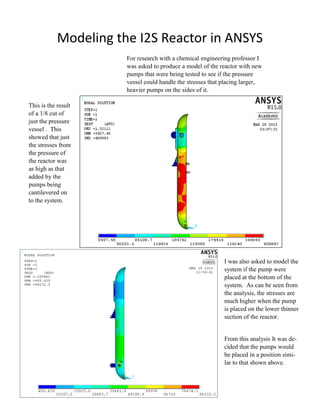
For research with a chemical engineering professor I
was asked to produce a model of the reactor with new
pumps that were being tested to see if the pressure
vessel could handle the stresses that placing larger,
heavier pumps on the sides of it.
This is the result
of a 1/8 cut of
just the pressure
vessel . This
showed that just
the stresses from
the pressure of
the reactor was
as high as that
added by the
pumps being
cantilevered on
to the system.
I was also asked to model the
system if the pump were
placed at the bottom of the
system. As can be seen from
the analysis, the stresses are
much higher when the pump
is placed on the lower thinner
section of the reactor.
From this analysis It was de-
cided that the pumps would
be placed in a position simi-
lar to that shown above.
2. Experiment to Find the Most Efficient Design
for a 3.8” Diameter Impeller
For Capstone our team was asked to design a cheaper
pump. We first looked into finding out which type of
impeller is most efficient at a diameter of 3.8 inches, a
forward curved impeller, a backward curved impeller,
or a straight finned impeller. After 3D printing these
three impellers, the forward and backward impellers at
an angle of attack of 18 degrees, we attached them to
the exact same motor setup and tested their outputs due
to pressure and flow. From this we were able to obtain
a set of efficiencies for each impeller.
Test Number
Efficiency.
This is what our test set-
up looked like. There
was a flow meter and a
pressure gauge to get the
results needed to calcu-
late the efficiency of the
impeller on each test.
Each of the tests were run at a different rota-
tional velocity. From the three different tests it
was clear to see that the straight bladed impel-
ler was the most efficient. From this experi-
ment Our Capstone team decided to continue
making the pump with a straight bladed impel-
ler.
3. Designing the Capstone Pump for Manufacture
For capstone we were designing a cheaper pump that
was to be made by as many off the shelf parts as we
could, and only modify them slightly to make it cheap-
er. In the beginning our designs were only based on
what we needed. After looking at them from a manu-
facturing perspective and trying to keep them inexpen-
sive by making them quick to manufacture I redid the
design with one difficult piece and two easy to manu-
facture pieces.
Above is the beginning iteration when we had a tube
and cut a small notch in it for the wires to come out. To
the right the original end cap design also has a notch it
it for the wires, and the two parts would have to be
aligned during assembly. Below we decided that the
end cap would have a hole for the wires to be fed
through an off the shelf pin setup. And the pipe part
would no longer have the notch.
Just making these small changes can save a
lot of money in the long run with each part
saving time manufacturing or time assem-
bling the final product.
4. Prototyping using Different Methods
As a student at BYU I have been taught how to
use the Mill, Lathe, Band Saw, Table Saw, 3D
printer, and Laser Cutter to make prototypes for
our various projects. I have also gotten a lot of
experience on these machines for the projects that
my various classes have required.
For the pipsqueak engine above that we had
to make in a class, we were taught how to
use the mill and lathe for brass, aluminum
and steel.
For the robot on the left that was part of
Mechatronics class, many parts were cut on
the laser cutter and many other parts were
3D printed. There was also a lot of solder-
ing done on the circuit boards and some
welding needed for the basket on top.
For the prototype of the
pump that was made for cap-
stone we used the lathe, mill,
band saw, and CNC to get all
of the pieces that were need-
ed made. Also for earlier pro-
totypes the 3D printer and
laser cutter were also used.
5. Designing Using CAD
An important part of Mechanical Engineering is being able to use
CAD software to model your ideas to share with others on your
team. Over my college career I have used many of the software
packages available, but I have become quite adept at two in par-
ticular, Autodesk Inventor and Solidworks. Inventor I have had
to use for the research I have done on nuclear reactors and Solid-
works was used extensively for the work I did for our Capstone
team.
A quarter of the reactor with the
internals that was modeled in In-
ventor on display using ANSYS
workbench.
This is the full reactor vessel as
rendered in Inventor.
This is the turret of the robot that
was built for mechatronics, mod-
eled in Solidworks.
The exploded view of the pump
that was designed for capstone us-
ing Solidworks.
6. Evaluating Designs and Projects Using Different
Programming Languages
I have worked in many different programming languages while working on an un-
dergraduate degree. Mainly, I have used C, C++, MatLab, ANSYS MAPDL, Math-
matica, LabView and LaTeX. These codes have run a robot using a microcontroller,
a few math based programs, a GUI, Image Capture and many other things. Here
are some of the results of programming.