
Recommended
More Related Content
What's hot
What's hot (19)
Similar to RDT-112-PRELIM-LESSON-2-NOTES.docx
Similar to RDT-112-PRELIM-LESSON-2-NOTES.docx (20)
Recently uploaded
Recently uploaded (20)
RDT-112-PRELIM-LESSON-2-NOTES.docx
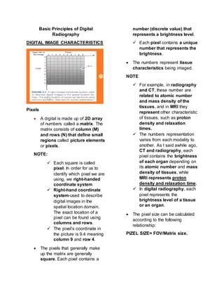
- 1. Basic Principles of Digital Radiography DIGITAL IMAGE CHARACTERISTICS Pixels A digital is made up of 2D array of numbers called a matrix. The matrix consists of column (M) and rows (N) that define small regions called picture elements or pixels. NOTE: Each square is called pixel. In order for us to identify which pixel we are using, we right-handed coordinate system Right-hand coordinate system-used to describe digital images in the spatial location domain. The exact location of a pixel can be found using columns and rows. The pixel’s coordinate in the picture is 9.4 meaning column 9 and row 4. The pixels that generally make up the matrix are generally square. Each pixel contains a number (discrete value) that represents a brightness level. Each pixel contains a unique number that represents the brightness. The numbers represent tissue characteristics being imaged. NOTE For example, in radiography and CT, these number are related to atomic number and mass density of the tissues, and in MRI they represent other characteristic of tissues, such as proton density and relaxation times. The numbers representation varies from each modality to another. As I said awhile ago, CT and radiography, each pixel contains the brightness of each organ depending on its atomic number and mass density of tissues, while MRI represents proton density and relaxation time. In digital radiography, each pixel represents the brightness level of a tissue or an organ. The pixel size can be calculated according to the following relationship: PIZEL SIZE= FOV/Matrix size.
- 2. NOTE: If you have both of the factor such as FOV/Matrix size you can readily calculate for pixel size. For digital imaging modalities, the larger the matrix size, the smaller the pixel size (for the same FOV) and the better spatial resolution. NOTE: As you can see the picture with the same FOV, as you can see the pixels the first picture is smaller and its getting larger as the progress with the images. As you can see the image resolution in the first picture is much better than the other larger pixel size. The first picture has smaller pixel size and same FOV. The smaller pixel size, the spatial resolution is better compared to larger pixel size. MATRIX SIZE Generally diagnostic digital images are rectangular in shape (portrait orientation). When imaging a patient with a digital imaging modality, the operator selects the matrix size, sometimes referred to as the field of view (FOV). NOTE: FOV can be synonymous to matrix size but for clarity, the FOV, if magzoom ka ng picture, the FOV is lesser (smaller) kaysa magzoom out ka sa isa ka picture. When you zoom a picture, your FOV is smaller because because small areas are covered unlike when you zoom out, the FOV is larger because it covers a larger area. But when it comes to matrix size, it depends on the number of pixels that is present in the matrix. The larger the matrix size, and smaller the pixels, the better spatial resolution. The larger the pixel size then larger pajud imong matrix the lower the spatial resolution. Your spatial resolution is pixel dependent or pixel emitted. The smaller the pixel size, the higher the resolution.
- 3. Matrix Size As images becomes larger, they require more processing time, storage space and take more time to be transmitted to a remote location. Note: If we choose to download a file that has one 1GB when compared to downloading of file that has only 10 megabytes, we can differentiate that 1GB is larger and it will require faster internet connection than that of the 10-megabyte file. It is the same with the files in digital radiography, as the images become larger, it requires more processing time, storage space, since we have a larger image when compared to small image, it will take up more storage and take more time to be transmitted to a remote location. The transferring of image from one area to another would be difficult if the image has a large matrix size. Spatial Resolution Spatial Resolution refers to the ability to image small objects that have high subject contrast, such as bone-soft tissue interface, a breast microcalcification, or a calcified lung nodule. Note: Image A has a better resolution since we can see the borders of the bones rather than Image B since Image B is pixilated. The image quality in image A is also better than image B. Bit Depth The number of bits per pixel is the bit depth. o In each pixel there is a bit. This bit represents the shades of gray that will be produce in an image for each pixel. Because this binary number system used the base 2, kbits=2k. Therefore, each pixel will have 2k gray levels. o Letter k represents how many bits or pixels are present. For example, in a digital image with bit depth of 2, each pixel will have 22 (4) gray levels. Note: Since nakabase 2 tayo sa bit depth ang base lang dyud is dapat 2
- 4. and since bit depth is also 2 = 22 = 4 gray levels. Notes: For the first image the bits per pixel is 1 and the its shades of gray consists of only 2 and there only 2 colors present the black and white which projects a HIGH CONTRAST image. But with the 24 it will provide us with 16 shades of gray. It is a much better image than with 1 bit per pixel. o As the number goes LARGER, the image provided would have a better image. Contrast Resolution Contrast Resolution is the ability to distinguish anatomical structures of similar subject contrast such as liver-spleen and gray matter- white matter. The actual size of the objects that can imaged is always smaller under conditions of high subject contrast than under conditions of low subject contrast. o If the images provided are HIGH SUBJECT CONTRAST the actual size of the object being imaged is SMALLER while if the image is LOW SUBJECT CONTRAST the actual size of the object being imaged is LARGER. Note: The liver and the kidney has almost the same contrast resolution. Note Both the spatial and contrast resolution focuses on detail however SPATIAL RESOLUTION most likely compared to blur. o Higher number of pixels the better is the spatial resolution o Smaller number of pixels it would appear blurred or low spatial resolution.
- 5. CONTRAST RESOLUTION o More shades of gray the more detail you can see or an INCREASE in detail o The higher the contrast resolution is, the higher the detail, the higher the shades of gray. o Contrast resolution and bit depth are somewhat connected. Digital Receptor Digital receptor is the device that intercepts the x-ray beam after it has passed through the patient’s body and produces an image in digital form, that is, a matrix of pixels, each with a numerical value. This replaces the cassette containing intensifying screens and film that is used in non-digital, film-screen radiography. Note: Computed radiography much more widely available than screen film radiography because it much easier to work with and lesser work load for the staff compared with film-screen that you have to process films on the darkroom, you have to have a passbox, you have to have an automatic processor. With the computed radiography and digital radiography, it is much easier for the radiologic technologist to process the images. DIGITAL RECEPTORS THAT HAVE BEEN USED FOR AGES Charge-Coupled Device (CCD) Charge-Coupled Device (CCD) is the light sensing element for most digital cameras Has three principal advantageous imaging characteristics - Sensitivity - Dynamic Range - Size Charge-Coupled Device (CCD) is a silicon-based semiconductor that converts visible light into electrical signal “Indirect (DR) because it still needs to be converted into light through the use of a phosphor, needs to be converted into another type of energy before it can be converted into digital signal.” Sensitivity is the ability of the CCD to detect and respond to very low levels of visible light. The sensitivity is important for photographing the heavens through a telescope and for low patient radiation dose in digital imaging. Note: Since we are in the digital imaging field, sensitivity should be higher or the digital receptors we should use must be sensitive enough. Compared to screen speed, in film-screen radiography, dapat high-screen speed talaga sya because this will result to lower patient dose but with the sacrifice of spatial resolution. Dynamic Range is the ability of the Charged-Coupled Device (CCD) to respond to a wide range of light intensity, from very dim to very bright. Note: it doesn’t matter if is produced with low level of light or very bright light because the CCD has wide dynamic range which can respond to low and high level of light.
- 6. At very low x-ray exposure, the response of a Charge-Coupled Device (CCD) system is greater than that of the screen film. This should result in lower patient dose during DR. Note: Charge-Coupled Device (CCD) is more sensitive than the intensifying screen of the film-screen radiography. Patient dose is lower because Charge- Coupled Device (CCD) is very sensitive, it will respond to a very low level of light produced by the phosphor compared to intensifying screen or film-screen radiography. Charge-Coupled Device (CCD) is very small, making it highly adaptable to DR in its various forms. Measures approximately 1 to 2 cm, but the pixel size is an exceptional 100 x 100 μm. Charge-Coupled Devices (CCDs) can be tiled to receive the light from an area x- ray beam as it interacts with a scintillation phosphor such as cesium Iodide (Csl). “A compact device and it is very small in size but it can provide 100 x 100 pixel size. Smaller pixel size can provide a better spatial resolution for the image” “Coupling element of CCD – Fiber optic taper” “Fiber optic taper connects the emitted light from the cesium Iodide phosphor towards the CCD array.” DONE CHARGED-COUPLED DEVICE DONE CHARGED-COUPLED DEVICE DONE CHARGED-COUPLED DEVICE Complimentary Metal Oxide Systems (CMOS) It is still indirect because it needs a phosphor to convert light into a digital signal or electrical signal. When x-rays interact with the scintillator, x-rays are converted into light and the semiconductor within the system converts the visible light into an electrical signal. When compared to a CCD, CMOS is: - Susceptible to noise - Light intensity is lower - Uses less energy - Are inexpensive - Tend to have lower quality “Images produced by a CMOS has an increase in image noise” “Light intensity is lower meaning more x- rays are needed to produce // in order for the light to increase to and it can be detected by the CMOS” It uses less electrical energy and inexpensive. More likely, CMOS is the knock-off version of CCD “CMOS is the lower or budget version of CCD” “Sacrifice: Lower image quality = higher patient dose” INDIRECT DR: CESIUM IODIDE/AMORPHOUS SILICON An early application of DR is involved the use of CsI to capture the x-ray as well as the transmission of the resulting scintillation light to a collection element.
- 7. The collection element is a silicon sandwiched as a TFT. -Silicon is a semiconductor that is usually grown as a crystal. When identified as amorphous silicon is not crystalline but is a fluid that can be painted onto a supporting surface. NOTES: The combination of cesium iodide and amorphous silicon, the phosphor will be the cesium iodide When x-ray interacts with cesium iodide, cesium iodide converts the x-ray into light, and then it will transmit the light into the amorphous silicon which acts as TFT (Thin film transistor) We are using SILICON as a material for our thin film transistor (TFT), it shouldn’t be crystal since originally the silicon is crystal but it cannot be installed to our collecting element or to the DR system if it is crystal form. That’s why its transformed into amorphous silicon in order for it to be painted, so that it would be installed properly and easily in digital radiography system. -The DR image receptor is fabricated into individual pixels. Each pixel has light-sensitive face of a-Si with a capacitor and a TFT embedded. - CsI/a-Si is an indirect DR process by which x-rays are converted first to light and then to electrical signal. NOTES: Each square is a pixel, that contains the phase of amorphous silicon TFT which is the yellow one and the storage capacitor which is the white one. Before the TFT or the amorphous silicon can transform light into x- rays, the x-ray must interact with cesium iodide in order for it to be transformed into light. -The percentage of the pixel face that is sensitive to x-rays is the fill factor. The fill factor is approximately 80%; therefore 20% of the x-rays beam does not contribute to the image. NOTES: Pixel phase is not composed entirely of amorphous silicon, some of it have thin film transistor (TFT) and storage capacitor, which does not provide a perfect 100% film factor Hindi ma-convert lahat ng x-rays into electrical signal because of the existence of TFT and storage capacitor. 20% can be provided if it has been converted into light towards the storage capacitor and TFT -This represents one of the dilemmas for DR. As a pixel size is reduced, spatial resolution improves but at the expense of the patient radiation dose. With smaller pixels, the fill factor is reduced, and x-ray intensity must be increased to maintain adequate signal strength.
- 8. -Spatial resolution in DR is pixel limited NOTES: Since the fill factor is only 80%, we have to increase it somehow if you want to provide a good spatial resolution. An increased in spatial resolution will provide more exposure and more patient radiation dose. In order to have a good spatial resolution you must have smaller pixels. If we have smaller pixels, the fill factor will be reduced and in order for the fill factor to be increased we have to increased x-ray intensity, which provides adequate signal. Increased spatial resolution but sacrificed on the patient radiation dose. Spatial resolution depends on the size of the pixel Smaller pixel size, spatial resolution is INCREASED. Larger pixel, spatial resolution is DECREASED. -What has been described for the CsI/a- Si image receptor can be repeated for the GdOS (Gadolinium oxysulfide) screen-film speed was increased, spatial resolution was reduced because of light dispersion in the GdOS NOTES: The alternative of cesium iodide is GdOS (Gadolinium oxysulfide) Gadolinium oxysulfide is one of the materials for the film screen/intensifying screen, it can also be applied in DR as the phosphor of choice combined with amorphous silicon GdOS’ phosphor speed is increased, that means that the image receptor is more sensitive. Which means there is lower patient exposure dose. Spatial resolution is reduced because light dispersion of GdOS is increased When compared Cesium iodide to GdOS, GdOS disperses light even more which brings spatial resolution to its lowest when compared to cesium iodide. -Such is not the case with DR. Increasing thickness of GdOS (Gadolinium oxysulfide) in a DR image receptor increases the speed of the system with no compromise in spatial resolution. NOTES: In screen-film radiography for specifically in the intensifying screens, the more we increase thickness of the phosphor layer in an intensifying screen increases its screen speed. An increased in screen speed provides lower patient dose which provides lesser spatial resolution increasing the thickness of the phosphor increases the speed with no compromise in spatial resolution.
- 9. The more you thicken the phosphor in the DR, more fast your image receptor, but spatial resolution becomes higher with no compromise. In film screen radiography, intensifying screen, if you are increasing the thickness of the phosphor layer, there will be a sacrifice on the image quality, because the patient dose is lower and the film speed is higher. DIRECT DR: AMORPHOUS SELENIUM It is called DIRECT DR because when x-rays interact with the amorphous selenium the material of choice for the collecting element, the amorphous selenium converts these x-rays into electrical signal directly. -This DR modality is identified by some as direct DR because no scintillation phosphor is involved. The image- forming-x-ray beam interacts directly with amorphous selenium (a-Se), producing a charged pair. -The a-Se is both the capture element and coupling element. DIRECT DR: AMORPHOUS SELENIUM Why is it called Direct DR? It’s because when x-rays interact with the amorphous selenium, it converts these x-rays into electrical signal directly. No need for a phosphor so that to convert x-rays into light. But, use amorphous selenium converts x-rays directly into electrical signal. a-Se is a direct DR process by which x- rays are converted directly to electric signal. The a-Se is approximately 200 μm thick and is sandwiched between charged electrodes. (top electrode and pixel electrode) X-rays incident on the a-Se create electron hole pairs through direct ionization of selenium. The created charge is collected by a storage capacitor and remains there until the signal is read by the switching action of the TFT.
- 10. When x-rays interact with the amorphous selenium, electron holes are created or electron hole pairs are created because of direct ionization. Direct ionization it removes directly the outer shell electrons of amorphous selenium. When that happens, those charged electrons will then go to the storage capacitor, will be stored here until such time the TFT will open. Charged particles from the storage capacitor go towards the TFT when the TFT opens. (So si TFT, siya na bahala mag produce ng image which will be projected here in this glass substrate) ADDITIONAL NOTE sa INDIRECT DR: CESIUM IODIDE/AMORPHOUS SILICON When x-rays interact with the phosphor, the cesium iodide phosphor, the light produced by the phosphor will be then directed towards the amorphous silicon as a TFT. Amorphous silicon functions as a thin film transistor. This thin film transistor in indirect DR is the one transforms x-rays into electrical signal. Then the electrical signal will then be converted into an image. PHOTOSTIMULABLE PHOSPHOR PLATE (PSP) The PSP, barium fluorohalide, is fashioned similarly to a radiographic intensifying screen. Because the latent image occurs in the form of metastable electrons. Latent image in film-screen radiography in the form of silver grains or the formation of silver grains, here in photostimulable phosphor plate in computed radiography, it is in the form of metastable electrons. When x-rays interact with the phosphor in the imaging plate, electrons get excited and they return from their excited state to the ground state through the use of laser light. PSP particles are randomly positioned throughout a binder. (so compared to radiographic film, the binder there is gelatin, binds the silver halide crystals in place. For the PSP, wala gi mention ang unsa na material nasa binder but it has also the same responsibility as a radiographic film, the binder randomly positions and holds the PSP particles in place.)
- 11. The most common phosphors with characteristics favorable for CR are barium fluorohalide bromides and iodides with activators (BaFBr:Eu and BaFI:Eu). (some materials used in PSP are barium fluorobromide and barium flouroiodide.) The process involves the use of laser beam to allow the electrons to return to its ground state after the emission of light detected by the photodetector. So, the coupling element here is the fiber optics pa rin, same with the charged couple device, cesium iodide. So, the light-collection optics will collect the light emitted by the photostimulable phosphor and then it will be detected by the photodetector. (Exclude SPR, this is dedicated for Computed Tomography) For CR, x-rays interact with barium fluorohalide or barium fluorobromide or barium fluoroiodide. And the light emitted by the capture element will be sensed by your fiber optics or your lens and will be detected by your collecting element which is your photodetector. The coupling element connects the light emitted from the capture elements towards the collecting element which is the photodetector. In indirect DR, we use two types of phosphor, the cesium iodide and gadolinium oxysulfide. When x-rays interact with these phosphors, fiber optics and contact layer (amorphous silicon which is painted onto the Film Thin Transistor (TFT)) will connect the light emitted towards the collecting element which is the CCD CMOS and TFT In direct DR, amorphous selenium, when it interacts with the x-rays, converts x-rays into electrical signals through direct
- 12. ionization, removal of outer shell electrons from the amorphous selenium going to the storage capacitor and then, when the TFT is open, electrical charge will go to the TFT and image will be presented through the glass substrate. Remember that TFTs are usually combined with liquid crystal display (LCD) that is why in amorphous selenium, when the TFT opens, it can readily provide the image. After discussing the two modalities involved in this subject, now we ask ourselves, what are the differences between Computed and (Direct) Digital Radiography?
- 13. CR (Computed Radiography) DR (Direct) (Digital Radiography) Mechanism X-rays interact with the electrons of the phosphor raising them in a metastable state. A laser beam is introduced in order for the electrons to return to ground state while emitting visible light which are then detected by photodetectors X-rays are directly converted into x-rays through direct ionization of selenium thereby creating electron hole pairs. The created charge is collected by a storage capacitor. Recording Medium PSP Plate or Imaging Plate Amorphous Selenium Processing Involves the use of a reader (laser beam is introduced so that electrons emit visible light) No need for processing after x- rays are bombarded, image appears immediately on the screen Speed Slower Faster Availability Widely available Only higher level hospitals Initial Cost Cheaper. Can adapt to previous film screen system Expensive. Needs a new setup Cassette Rigidity Can withstand rough handling Fragile Image Quality Lower Better Workload Increased work because of removal of cassette from stand/bucky then placing on the reader Lesser workload because it only involves changing the cassette’s position from the bucky to the vertical stand and vice versa
- 14. NOTES: Mechanism (for CR) X-rays interact with the capture element which is the barium fluorohalide and then electrons are raised into metastable state and laser light or highly collimated laser beam is introduced in order for the electrons to return to their ground state. And then, with the transition of electrons into the ground state, visible light is emitted which will be transported by the fiber optics which are coping elements towards the collecting element which is the photodetector Mechanism (for DR) Deretso na sya. X-rays are converted into electrical signals through direct ionization. Removal of outer shell electrons into amorphous selenium, stored into the storage capacitor. And then, when the film bin transistor opens or searches open, electrical charges will go there and then images are displayed in a glass substrate. Recording Medium (CR) -most specifically the barium fluorohalide or barium fluorobromide or barium fluoroiodide Processing (CR) -Kinahanglan pa ug reader in order for the image to be displayed. Processing (DR) -Once x-rays interact with the amorphous selenium, images will be directly displayed on the monitor. Speed (CR) -daghan pa kayo kag buhaton, after exposure you have to feed it on the reader and then iread pa sya sa reader, there are so many processes that can happen. Speed (DR) -expose mo lang and the images will be displayed on the monitor. Availability (CR) -available in clinics and hospitals because film-screens are very tedious, we have to maintain automatic processor, we have to buy chemicals Availability (DR) -Davao Doctor’s Hospital has direct radiography Initial Cost (CR) -those who want to transform from film- screen to CR most likely recommended sa mga manufacturer is the CR, it is cheaper because maretain pa ang x-ray tube, maretain pa ang radiographic table Initial Cost (DR) -expensive sya kasi you have to dispose the reader, the cassette, you will dispose the x-ray tube and all because you need a new setup
- 15. Cassette Rigidity (CR) -although how many times mo sya mabagsak or matukudan, it can withstand, it is strong enough to handle those circumstances Cassette Rigidity (DR) -must be very careful in using the DR because the cassette is 5 million in total (Davao Doctor’s Hospital) -one drop it can already be broken. Image Quality (CR) -uses phosphor -converts x-rays into light -there is still a need for visible light, so when the visible light is involved, the image quality is lower. Image Quality (DR) -better because it does not involve intensifying screens -it does not also involve phosphor which converts light and then light into digital signal Workload (CR) -medyo tedious sya because you have to get the cassette from the stand or from the radiographic table or the bucky and then you place it to the reader, and you wait for few minutes in order for it to appear on the screen. Workload (DR) -lesser workload because reader is not utilized, you don’t have to put the cassette in the reader since x-rays are converted directly into electrical signal and images pop up directly on your screens. All you have to do is to change the position of the cassette into vertical stand, if you are going to change to radiographic table, just change the vertical stand to radiographic table