2. Electric Measurements
in Direct Current (DC) A constant electric voltage, called
DC voltage, applied across a closed
electric circuit, can send an electric
current of constant value.
How can we measure a constant
electric voltage and how can we
measure an electric current?
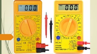
3. Activity 1:
Using a digital voltmeter
Take a multimeter functioning as a voltmeter.
Select the highest range in the zone 𝑉𝐷𝐶.
Connect the voltmeter across a 6 volt dry cell (Fig. 1a)
How is the Voltmeter connected?
To what terminal of the dry cell must the terminal
COM of the voltmeter be connected?
What does the voltmeter indicate?
Choose the most convenient range to measure the
voltage of the Dry Cell (Fig. 1b)
What is meant by “most convenient range”?
What does the voltmeter indicate now?
Is the indicated voltage constant?
what does the voltmeter indicate if the
connections of the dry cell are reversed?
To the negative pole
6 Volt
Greater
but closer
6.34 Volt
Yes
-6.34 Volt Same value but negative
In Parallel
4. Activity 2:
Using a digital ammeter
Take a multimeter functioning as an ammeter.
Select the highest range in the zone 𝐴 𝐷𝐶.
Connect the ammeter in series with a lamp and a switch across
a 6 volt dry cell (Fig. 2a)
How is the ammeter connected?
To what terminal of the dry cell must the terminal COM of the
ammeter be connected?
The switch is open. (Fig. 2b)
What does the ammeter indicate?
The switch is closed. (Fig. 2c)
Does the ammeter indicate a value?
Choose the most convenient range (Fig. 2d)
What is meant by “most convenient range”?
What does the ammeter indicate now?
Is the indicated current constant?
When the electric current has a constant value, it is called a
direct current.
Is the current measured by the ammeter a DC?
To the negative pole
0 A
Greater but closer
0.43 A
Yes
yes
In Series
yes
6. Activity 3:
Using an Oscilloscope
Switch on the oscilloscope.
Choose the Vertical Sensitivity (Y amplitude gain) 𝑆 𝑉 = 2𝑉/𝑑𝑖𝑣
and Horizontal Sensitivity (Time base) 𝑆ℎ 𝑜𝑟 𝑉𝑏 = 2𝑚𝑠/𝑑𝑖𝑣
Connect the 6 volt dry cell between the input A and M (phase
and ground) of the oscilloscope (Fig. 2a)
How is the oscilloscope connected?
What is the number Y1 of divisions by which the luminous line is
displaced?
Calculate using the formula U = Sv × Y1 the value of U.
Connect a Digital voltmeter across the dry cell.
What value does it indicate?
Is this value equal to that calculated above from the
oscilloscope?
Can the oscilloscope be used as a voltmeter?
6 V
Yes
yes
In Parallel
Y1 = + 3 div
U = Sv × Y1 = 2 v/div × 3 div = 6V
7. Activity 3:
Using an Oscilloscope
Choose now the Vertical Sensitivity 𝑆 𝑉 = 5 V/div
What is the number of divisions by which the
luminous line is displaced?
Calculate U
Do you obtain the same value?
Choose different values for the time base
𝑉𝑏 = 0.2 ms/div for example.
Calculate U for each value of Vb.
Does the value of U change?
Is this voltage a DC voltage?
1.2 division
Same as
No
yes
yes
U = Sv × Y1 = 5 v/div × 1.2 div = 6V
8. Laws of Voltages and
of Currents In an electric circuit the components
may be connected in series or in
parallel.
What are the laws of voltage across
these components and what are the
laws of the current they carry?
9. Activity 4:
Series Circuit
Connect the following electric circuit: the two lamps
L1 (3.5 V, 30 mA) and L2 (6V, 60 mA), the switch and
the two ammeters are all connected in series across a
6 volt dry cell. Close the switch
What are the indications I1 of ammeter A1 and I2 of
ammeter A2?
Does the same current flow in the components of a
series circuit?
Remove the ammeters and connect a voltmeter
across each lamp and a third voltmeter across the
terminals of the Lamps together. Close the switch
What is the indication U1 of the voltmeter V1?
What is the indication U2 of the voltmeter V2?
What is the indication U of the voltmeter V3?
Compare U and (U1 +U2). are they equal?
What laws of series circuit does this experiment show
evidence of?
Yes
U2 = 3.48 V
U = 6.21 V
U = U1 + U2
Law of Uniqueness of current ( I is Constant)
and Law of addition of voltage
I1 = 0.316 A while I2 = 0.319 A
U1 = 2.7 V
10. Activity 5:
Parallel Circuit
Connect the following electric circuit: the two lamps L1 (3.5 V, 30
mA) and L2 (6V, 60 mA) are connected in parallel across the 6
volt dry cell. Insert an ammeter in series with each lamp and a
third ammeter in the main branch. Choose the highest range in
each Ammeter. Close the switch
Choose now the most convenient range in each ammeter.
What is the value I1 of the current indicated by the
ammeter A1?
What is the value I2 of the current indicated by the
ammeter A2?
What is the value I of the current indicated by the
ammeter A?
Compare I and I1 + I2. are they equal?
connect a voltmeter across each lamp and a third voltmeter
across the dry cell
what does each of the three voltmeters indicate?
are these voltages all equal in a parallel circuit?
What law of parallel circuits does this experiment show
evidence of?
I2 = 0.413 A
U = U1 = U2 =6V
Law of Uniqueness of voltage ( U is Constant) and
Law of addition of current
I1 = 0.441 A
Yes
I = 0.848 A
I = I1 + I2 Do the lamps Shine the same?
L1 shines brightly While L2
Normally
11. The Voltmeter and the oscilloscope measure the electric voltage between two
points of an electric circuit when they are connected to these points (In parallel)
The ammeter, inserted in series in a circuit, measures the electric current
carried by this circuit.
When many components are connected in Series:
The current is the same in all the components of the series circuit. (I = I1 = I2 = I3 = ……)
The voltage across these components is additive (U = U1 + U2 + U3 + …….)
When many components are connected in Parallel:
The main current in the circuit is the sum of the branch currents in the parallel branches.
(I = I1 + I2 + I3 + ……)
The voltage is the same across all these components (U = U1 = U2 = U3 = …….)